HAL Id: hal-00655643
https://hal.archives-ouvertes.fr/hal-00655643
Submitted on 1 Jan 2012
HAL is a multi-disciplinary open access
archive for the deposit and dissemination of
sci-entific research documents, whether they are
pub-lished or not. The documents may come from
teaching and research institutions in France or
abroad, or from public or private research centers.
L’archive ouverte pluridisciplinaire HAL, est
destinée au dépôt et à la diffusion de documents
scientifiques de niveau recherche, publiés ou non,
émanant des établissements d’enseignement et de
recherche français ou étrangers, des laboratoires
publics ou privés.
AND SECOND ORDER HYPERBOLIC SYSTEM
Xiaoying Dai, Yvon Maday
To cite this version:
Xiaoying Dai, Yvon Maday. STABLE PARAREAL IN TIME METHOD FOR FIRST AND SECOND
ORDER HYPERBOLIC SYSTEM. 2011. �hal-00655643�
ORDER HYPERBOLIC SYSTEM∗ XIAOYING DAI † AND YVON MADAY‡ § ¶
Abstract. The parareal in time algorithm allows to perform parallel simulations of time depen-dent problems. This algorithm has been implemented on many types of time dependepen-dent problems with some success. Recent contributions have allowed to extend the domain of application of the parareal in time algorithm so as to handle long time simulations of Hamiltonian systems. This improvement has managed to avoid the fatal large lack of accuracy of the plain parareal in time algo-rithm consequence of the fact that the plain parareal in time algoalgo-rithm does not conserve invariants. A somehow similar difficulty occurs for problems where the solution lacks regularity, either initially or in the evolution, like for the solution to hyperbolic system of conservation laws. In this paper we identify the problem of lack of stability of the parareal in time algorithm and propose a simple way to cure it. The new method is used to solve a linear wave equation and a non linear Burger’s equation, the results illustrate the stability of this variant of the parareal in time algorithm.
Key words. parareal in time algorithm, parallelisation, time discretization, evolution equations, hyperbolic system, wave equation.
AMS subject classifications. 65L05, 65P10, 65Y05
1. Introduction. Parallel in time algorithms represent a new competitive way of using the ever increasing number of cores in today’s supercomputers platforms in cases where classical domain decomposition methods either are of no relevance (for systems of differential equations) or in cases where the scalability of the sole domain decomposition (for evolution PDE’s) gets to saturation. This kind of algorithm in the 4th direction has received too little attention in the literature in the past due
to the inherent sequential nature of the time direction: it seems indeed difficult to simulate what will arrive in the far future, e.g. next week, without knowing in details what will arrive in the close future, e.g. tomorrow and each day of the current week. Due to the paramount importance of finding new ways for parallelisation, going together with the ever increasing number of processors present in the new generations of architectures, algorithms such as parareal in time, parallel deferred corrections or parallel exponential integrators have become an active research topic showing promising applicability for large-scale computations and perhaps one way to go to exascale computations. We refer e.g. to the book of K. Burrage [4] for a synthetic approach on the subject (see also [5]). In this book, the various techniques of parallel in time algorithms are classified into three categories: (i) parallelism across the system, (ii) parallelism across the method and (iii) parallelism across the time.
The parareal in time algorithm pioneered in [14] extended later in [1, 3, 18] under a form much better tuned to the treatment of nonlinear problems enters in the third category above (see [20] for a first algorithm in this category). It combines two propagators, one fine and one coarse, in a predictor-corrector manner that allows to use the fine propagator in parallel on the various processors, while the coarse
∗This work was supported by ANR-06-CIS6-007.
†LSEC, Institute of Computational Mathematics and Scientific/Engineering Computing,
Academy of Mathematics and Systems Science, Chinese Academy of Sciences, Beijing 100190, China ([email protected]).
‡UPMC Univ Paris 06, UMR 7598, Laboratoire Jacques-Louis Lions, F-75005, Paris, France §CNRS, UMR 7598, Laboratoire Jacques-Louis Lions, F-75005, Paris, France
¶Division of Applied Mathematics, Brown University, Providence, RI, USA
propagator is solved in a sequential manner. The algorithm provides good, provable convergence, for diffusive PDEs such as parabolic type problem. However, several studies have shown some instabilities for hyperbolic equations [8, 11, 19, 6] and the numerical analysis performed on simple examples or partial differential equations in [3, 2, 21] allows us to understand this behavior.
A challenging field of application for parallel in time propagators is for long time simulation of Hamiltonian systems. Here also the plain method lacks the geomet-ric properties that are essential to guarantee the quality of the approximation. Let us remind that these geometric properties lead to the convergence of the algorithm towards the solution of the original systems on long time simulations. These proper-ties —either the symplecticity or the symmetry of the scheme — are not preserved for the parareal scheme even if the basics coarse and fine propagators are symplectic or symmetric. A cure to this lack of geometric properties has been proposed in [7], based on two ingredients: the first one is the symmetrization of the parareal in time algorithm that leads to a new multistep schemes. This ingredient alone is not suffi-cient though to provide a correct algorithm for Hamiltonian systems. Indeed, some resonances are artificially introduced by the parareal strategy itself as is explained in [7]; they prevent the symmetric variant of behaving well. The second ingredient that has been introduced in [7] consists simply, after each correction of the predictor corrector scheme, to project the solution coming out the parareal in time algorithm, on the manifold expressing the preservation of some basic invariant quantities of the Hamiltonian system. This is quite simple to implement, at least in its basic formula-tion (there exists a symmetric version based on a more involved implicit resoluformula-tion of projection on the manifold).
Following this second idea advocated to stabilize the parareal in time algorithm for Hamiltonian system, we propose in this paper an extension of it allowing to cure the lack of stability that occurs when solving hyperbolic type problem. Another strategy, based on providing a much more involved correction procedure re-utilizing previously computed information has been proposed in [9, 10] and already improved the performance of the parareal in time algorithm for second-order hyperbolic systems. The method proposed here seems much more simple to implement and more general in scope and applications.
The remainder of this paper is organized as follows. In Section 2, we remind the basics on the plain parareal in time algorithm including the current state of the art on the stability and convergence analysis of the algorithm; we use this to introduce the proposed stable variant of the parareal scheme. In Section 3 we address the case of the wave equation, a simple second-order hyperbolic equation. The correction we propose is discussed in full details and the numerical simulation illustrates the good properties of the variant. In Section 4 we address the case of the Burgers’ equation, with small viscosity, here again the variant performs well. In Section 5 we present some elements of numerical analysis proving the stability of the proposed variant of the parareal scheme and finally some conclusions are drawn in Section 6.
2. Some elements on the parareal in time algorithm.
2.1. Basics on the parareal in time algorithm. Let us consider a possibly non-linear time dependent partial differential equation of the form
∂y
where y(t) takes its values in a Banach space B and A is a partial differential operator defined over B. We assume here that this problem is well posed, at least for some time: the solution y(t) exists for t ∈ [0, T ). More precisely, we assume that there exists a propagator E such that
y(t) = Et 0(y0),
named exact propagator. We note that, with obvious notations, we have
y(t) = Est(y(s)), ∀s, t, 0 ≤ s ≤ t ≤ T. (2.2)
Let us assume now that we want to simulate this PDE on the interval [0, T ), we thus introduce a discrete propagator F that is assumed to be a fine and precise approximation of the exact solution based on a discretization in time only. The propagator F can be based on an approximation using a time discretization and, e.g. the use of an Euler-type or a more involved scheme based on a small enough time step δt.
For instance, let us denote as T0 = 0, TN = T and Tn = n∆T (with ∆T = NT)
special times at which we are interested to consider snapshots of the solution y(Tn),
then, with notations similar as above (2.2), we have the approximation Yn= FTT0n(y0), n= 1, ..., N
we also have
Yn+1= FTTnn+1(Yn).
In what follows we present the parareal in time algorithm that allows to define a sequence {Yk}k,Yk ≡ (Y1k, Y2k, ..., YNk), such that, for any n, Ykn converges to Yn in
the space B as k goes to infinity. The definition of this sequence requires the avail-ability of another approximated propagator, denoted as G. This second propagator is assumed to be cheaper than F at the price of some inaccuracy. One can think im-mediately about having G based on a similar Euler scheme as F with the larger time step dT, δt << dT ≤ ∆T . But other possibilities are also offered: in addition to the solution scheme in time, a discretization in space has to be performed, for instance, the spacial discretization can be based on a finite element method, the coarse solver G can then be based both on a coarser time step and a coarser spacial discretization, we refer to [11] and [17] where such a strategy is followed. Another possibility consists in providing F with all the physics of the phenomenon while G will be based on a simplified physics (see eg [16] for an example).
Assume F and G are given, we can proceed to the definition of the sequence. Let us initiate Y0 by
Yn0= GTn
T0(y0), n= 1, ..., N (2.3)
Assume now Yk is known, the iterative process proceeds by setting Yk
0 = y(0), and, Yn+1k+1= GTn+1 Tn (Y k+1 n ) + F Tn+1 Tn (Y k n) − G Tn+1 Tn (Y k n), n= 1, ..., N. (2.4)
We first comment on the parallelization of the above algorithm. The initialization step (2.3) is sequential but involves the cheap coarse propagator. Then assuming that every (Yk
independent propagation problems that provide FTn+1
Tn (Y
k
n); we can either propagate
again (and now in parallel) the coarse solver to get GTn+1
Tn (Y
k
n), or just remember that
these quantities were computed during the previous step and stored, any way this is again parallel work. The corrector FTn+1
Tn (Y k n) − G Tn+1 Tn (Y k
n) can then be built, for any
nand the step can proceed. We finally solve the predictor based on the coarse solver GTn+1
Tn (Y
k+1
n ) — sequentially — and immediately correct it by adding the previously
computed corrections until convergence. Note that in this process, the fine solutions are only used on small propagation intervals and can be performed in parallel.
2.2. Numerical analysis of the parareal in time algorithm. We review in this subsection some elements on the stability and convergence of the parareal in time algorithm that have been first presented in [2]. Let us assume that there exists a sequence of Banach spaces Bj such that Bj+1 ⊂ Bj. It is also assumed that the
problem 2.1 is stable in these spaces, in the sense that there exists a constant C > 0, such that, for all j, 1 ≤ j ≤ J
∥E0t(y0)∥Bj ≤ C∥y0∥Bj (2.5)
The algorithm converges, under the following natural hypothesis: denoting by δF (resp. δG) the difference δFt
s= Est− Fst (resp. δGst= Est− Gts), we assume that there
exists a constant C > 0, such that, for all j, 1 ≤ j ≤ J
∀t ≥ 0, ∀τ ≥ 0, ∥Gtt+τ(x) − Gtt+τ(y)∥Bj ≤ (1 + Cτ )(∥x − y∥Bj). (2.6)
In addition let us assume that there exists a constant C > 0, such that, for all j,1 ≤ j ≤ J
∀t ≥ 0, ∀τ ≥ 0, ∥δFtt+τ(x) − δFtt+τ(y)∥Bj ≤ Cτ η∥x − y∥Bj+1, (2.7)
∥δGtt+τ(x) − δGt+τt (y)∥Bj ≤ Cτ ε∥x − y∥Bj+1, (2.8)
where η and ε are small quantities, typically, for the Euler scheme these are η = δt and ε = ∆T and C is a generic constant, independent of the quantities on the right hand side of the previous inequalities and on j ≤ J, but may depend on J.
Remark 1. For Euler schemes based on a time step δt for F and ∆T G, hypoth-esis (2.7) and (2.8) hold with η = δt and ε = ∆T respectively.
The convergence is stated in the following (see theorem 1 in [2])
Theorem 2.1. Assume that the discrete propagators F and G satisfy (2.6), (2.7) and (2.8), then the error between the exact solution and the solution provided by the parareal scheme (2.4) satisfies for any k ≥ 0:
∀n ≤ N, ∥Yk
n − y(Tn)∥B0≤ C(ε
k+1+ η)(1 + ∥y
Proof: The proof is done by induction over j ≥ 0 for the statement
∀i ≥ 0, ∥Ynj− y(Tn)∥Bi≤ C(ε
j+1+ η)(1 + ∥y
0∥Bi+j+1), (2.10)
which is obvious for j = 0 since it corresponds to the analysis of the plain coarse operator. Let us assume that it is true for j and let us prove it for j + 1. From the definition of Yn+1j+1, we write Yn+1j+1− y(Tn+1) = GTn+1 Tn (Y j+1 n ) + F Tn+1 Tn (Y j n) − G Tn+1 Tn (Y j n) − E Tn+1 Tn [y(T n)] = GTn+1 Tn (Y j+1 n ) − G Tn+1 Tn (y(T n)) +[ETn+1 Tn − G Tn+1 Tn ](Y j n) − [E Tn+1 Tn − G Tn+1 Tn ](y(T n)) −[ETn+1 Tn − F Tn+1 Tn ](Y j n) + [E Tn+1 Tn − F Tn+1 Tn ](y(T n)) −[ETn+1 Tn − F Tn+1 Tn ](y(T n))
or again with the notations introduced above Yn+1j+1− y(Tn+1) = G Tn+1 Tn (Y j+1 n ) − G Tn+1 Tn (y(T n)) +δGTn+1 Tn (Y j n) − δG Tn+1 Tn (y(T n)) −δFTn+1 Tn (Y j n) + δF Tn+1 Tn (y(T n)) −[ETn+1 Tn − F Tn+1 Tn ](y(T n))
hence by triangular inequality ∥Yn+1j+1− y(Tn+1)∥ Bi ≤ ∥G Tn+1 Tn (Y j+1 n ) − G Tn+1 Tn (y(T n))∥ Bi +∥δGTn+1 Tn (Y j n) − δG Tn+1 Tn (y(T n))∥ Bi +∥δFTn+1 Tn (Y j n) + δF Tn+1 Tn (y(T n))∥ Bi +∥[ETn+1 Tn − F Tn+1 Tn ](y(T n))∥ Bi
that from hypothesis (2.6), (2.7) and (2.8) can be upper bounded as follows ∥Yn+1j+1− y(Tn+1)∥
Bi ≤ (1 + C∆T )∥Y
j+1
n − y(Tn)∥Bi
+C∆T ε∥Ynj− y(Tn)∥Bi+1
+C∆T η∥Ynj− y(Tn)∥Bi+1+ C∆T η∥y(T
n)∥ Bi+1
the stability hypothesis (2.5) together with the induction hypothesis (2.10) allow to get
∥Yn+1j+1− y(Tn+1)∥Bi≤ (1 + C∆T )∥Y
j+1
n − y(Tn)∥Bi
+C∆T (ε + η)(εj+1+ η)∥y0∥Bi+j+2+ C∆T η∥y0∥Bi+1
≤ (1 + C∆T )∥Yj+1
n − y(Tn)∥Bi
+C∆T (εj+2+ η)∥y0∥Bi+j+2
from which we get (2.10) for j + 1 from the discrete Gronwall lemma, and the proof is complete.
It is interesting to notice two things at this level. First the constant C in (2.9) depends on k and T and this convergence result can be polluted on a long time range by a constant C that becomes too large. Second, the convergence results implies, of course, stability. Hence, provided that the initial condition is regular enough and remains regular the parareal in time algorithm is stable.
The previous remark explains actually the problem of the use of the parareal scheme when non dissipative PDE or PDE with small dissipation are simulated. This is the case for small viscosity parabolic problem as is explained in the next subsection. This is also the case for hyperbolic systems. We can illustrate this statement on two equations: the periodic wave equation and the periodic Burger’s equation for which, starting with regular enough initial condition solves or corrects the instability of the parareal in time algorithm in this situation. This allows to rectify somehow the statements that were done before in e.g. [10] where the stability problem occurs for second-order hyperbolic problems and not for parabolic and first-order hyperbolic problems. The problem is not really on the type of the equations (and certainly not on the order of the equations) but on the regularity of the solution, including the regularity of the initial condition.
2.3. Behavior on a parabolic case. We have performed a series of simple test on the linear parabolic equation, provided with periodic boundary conditions
∂u ∂t − µ ∂2u ∂x2 +∂u∂x = 0, u(x, 0) = u0(x), u(x, t) = u(x + 2π, t), (2.11) in the case where the viscosity µ is positive yet very small µ = 10−10. We have chosen a
standard spectral Fourier approximation in space (truncated series with N = 256 and chosen a second order in time implicit Euler scheme for a propagation over [0, T = 2]. The parareal in time algorithm is implemented with ∆T = 2.10−2, dT = 10−2 and
δt= 10−4.
The simulation are done in order to illustrate the behavior of the scheme as regards the regularity of the solution. We have thus chosen different types of initial conditions with different regularities by choosing u0(x) =∑uˆℓeiℓx with
ˆ uℓ= 0.5i |ℓ|p, if ℓ > 0 0, if ℓ = 0 −0.5i|ℓ|p, if ℓ < 0,
In the case of low regularity: p = 0.5 or p = 1, the relative error after 15 parareal iterations is about 100! There is no blow up, the iterations can continue, the error eventually going to zero. For p = 4 or even better p = 10, the convergence is achieved after very few iterations, as is expected from Theorem 2.1.
These simple computations provide a preliminary illustration that the behavior of the parareal in time algorithm is deeply linked to the regularity of the solution.
3. The periodic wave equation.
3.1. The basic Fourier discretization. We consider the following one dimen-sional wave equation with periodic boundary conditions: Find u such that
∂2u ∂t2 − c2 ∂ 2u ∂x2 = 0, u(x, 0) = f(x), ∂u ∂t(x, 0) = g(x),
u(x, t) = u(x + T, t), ∂u ∂x(x, t) =
∂u
∂x(x + T, t)
where f and g are periodic given initial condition, c stands for the speed of the wave, and T ∈ R+ represents the period.
The weak form of equation (3.1) is as follows: Find u such that ∀t > 0, u(., t) ∈ S= {v ∈ H1(0, T), v(0) = v(T)} (∂ 2u ∂t2, v) + c 2(∂u ∂x, ∂v ∂x) = 0, ∀v ∈ S, (3.2) here, (u, v) =∫0Tu¯vdx.
We use now the Fourier spectral method to semi discretize in space problem (3.2). That is, we choose
SN = span{eiℓ
2π
Tx, ℓ= −N, · · · , N }, (3.3)
and approximate u(x, t) by
uN(x, t) = N ∑ ℓ=−N ˆ uℓ(t)eiℓ 2π T x. (3.4)
Note that ˆuℓ(t) = 1T(uN(x, t), eiℓ
2π
Tx), as results from the equality (eiℓ 2π
Tx, eik 2π
Tx) =
Tδℓ,kwhere δℓ,k denotes the standard Kroneker symbol.
The solution uN is defined by a Galerkin approximation so as to satisfy
(∂ 2u N ∂t2 , vN) + c 2(∂uN ∂x , ∂vN ∂x ) = 0, ∀vN ∈ SN. (3.5) As is classical, this Galerkin approximation reduces to a system of differential equa-tions in the Fourier coefficients ˆuk(t). More precisely, let us choose iteratively vN =
eik2πTx, k ∈ [−N, N ] in (3.5). We then obtain the following system of independent
equations T∂ 2uˆ ℓ ∂t2 (t) + (2π)2 T ℓ 2 c2uˆℓ(t) = 0, ∀ℓ ∈ [−N, N ], (3.6)
that can be exactely solved. After resolution, we know all the coefficients ˆuℓ(t) in a
closed form, then from equation (3.4) we get the Galerkin approximation of u(x, t) in SN.
Next, using respectively v = ∂u
∂t in (3.2) and vN = ∂uN
∂t in (3.5) allows to derive,
for any time t ∥∂u ∂t(., t)∥ 2 L2(0,T)+ c2∥ ∂u ∂x(., t)∥ 2 L2(0,T)= ∥ ∂u ∂t(., 0)∥ 2 L2(0,T)+ c2∥ ∂u ∂x(., 0)∥ 2 L2(0,T) (3.7) and ∥∂uN ∂t (., t)∥ 2 L2(0,T)+ c2∥ ∂uN ∂x (., t)∥ 2 L2(0,T)= ∥ ∂uN ∂t (., 0)∥ 2 L2(0,T)+ c2∥ ∂uN ∂x (., 0)∥ 2 L2(0,T) (3.8) respectively. If we now introduce the following Hamiltonian
H(uN)(t) = ∥ ∂uN ∂t (., t)∥ 2 L2(0,T)+ c2∥ ∂uN ∂x (., t)∥ 2 L2(0,T) (3.9)
The conservation (3.8) reads for any time t
H(uN)(t) = H(uN)(0) (3.10)
Of course the numerical discretization in time should preserve this invariant . Remark 2. As is often the case for Hamiltonian system, this basic invariant (which is here the total energy for the wave equation) is not the only one available, for instance it is immediately seen on (3.6) that by defining
hℓ(v) = | ∂v ∂t| 2+ (2π T) 2 ℓ2c2|v|2, (3.11) for any ℓ, ℓ = −N, .., N , we have
∀t, hℓ(ˆuℓ)(t) = hℓ(ˆuℓ)(0) (3.12)
which provides 2N + 1 invariant quantities (we notice that H =∑Nℓ=−Nhℓ).
3.2. Illustration of the stability and instabilities of the plain parareal in time algorithm. In all what follows, the discrete solutions will always, for any time t, belong to SN and will result from a Galerkin process. We will thus denote by
unthe approximation (in time) of the value of uN(Tn) (hence the full approximation
of u(Tn)). In order to test the parareal in time algorithm on this simple second
order equation, we further discretize the semi discrete problem (3.5) by adding a time discretization, that is based, both for the coarse G∆T and the fine F∆T propagators,
on the velocity Verlet scheme which is a second order in time, stable and consistent with the preservation of invariants (the wave equation being an Hamiltonian system, the symplectic nature of the velocity Verlet scheme makes it a method of choice).
The plain parareal scheme reads: {
u0
n+1 = G∆T(u0n)
uk+1n+1 = G∆T(uk+1n ) + F∆T(ukn) − G∆T(ukn).
(3.13) We perform simulations with the discretization parameters equal to
1. T = 100, ∆T = 2.10−1, dT = 4.10−3, δt= 2.10−6.
2. N = 30.
for different initial conditions of different regularities: u0(x) =∑ℓ∈Zuˆℓeiℓ
2π Txwith ˆ uℓ= { 1 |ℓ|p, if ℓ ̸= 0 0, if ℓ = 0,
with p p = 1, 5 or 10. The cases with p = 1 and p = 5 diverges while the case with p = 10 converges.
3.3. Results with the plain parareal in time algorithm on a realistic test problem. In this example, the excitation is provided by a Ricker pulse, which is analytically defined as follows
1. T = 5000 m, c = 2000 m/s
2. and the initial conditions are f (x) = 0, g(x) = (1−2(fsπx−xc s)2) exp(−(fsπx−xc s)2).
Here, fs= 2.5 Hz, is the frequency and xs= 2500 m is the position of the vibration
source.
The numerical results are obtained with a coarse propagator G and fine propagator F that differ only with time step dT and δt, respectively :
1. T = 100, ∆T = 2.10−1, dT = 4.10−3, δt= 2.10−6.
2. N = 30.
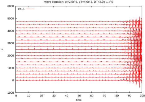
The plot showing the evolution in time of the solution obtained after 15 iterations at different positions in the periodic space [0, , T] on figure 3.1 reveals an instability visible starting at time t = 80. The situation is even worse after 25 iterations. Actu-ally this is one case that illustrates the bad behavior of the parareal in time algorithm for this hyperbolic equation. Note however that for many other choices of the dis-cretization parameters δt or dT or even N but the very same initial condition, the simulation is perfectly fine, stable and convergent. The instability is thus not system-atic, and changing slightly the discretization parameters, is often enough to make the scheme work. The plain parareal in time algorithm does lack of robustness, and this is what we want to correct in what follows.
-1000 0 1000 2000 3000 4000 5000 6000 0 10 20 30 40 50 60 70 80 90 100 x time
wave equation: dt=2.0e-6, dT=4.0e-3, DT=2.0e-1, PS k=15
Fig. 3.1. Vibration at different positions obtained by the parareal method(δt = 2.10−6, dT =
4.10−3,∆T = 2.10−1) revealing the instabilities.
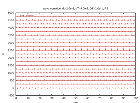
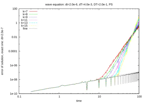
The exact solution shown on the next plot (figure 3.2) illustrates the differences. The plots of the error between the exact solution and the solution obtained after k iterations, with k = 1, .., 15 (see figures 3.3 and 3.4) illustrate clearly that the solution obtained by the parareal in time algorithm
1. converges for short time, e.g. only 7 iterations are sufficient to recover the solution obtained with the sole sequential fine propagator at time equal to 10.
2. does not converge for longer propagations, here for a time equal to 100 3. During the first 5 to 6 iterations the error of the parareal in time algorithm
is dominated by the error of the coarse scheme, but after k = 6, the error increases largely to values that are order 1 and bigger
4. After 15 iterations of the parareal in time algorithm the parareal solution is computed with an acceptable error until time t ≃ 30 only.
-500 0 500 1000 1500 2000 2500 3000 3500 4000 4500 5000 0 10 20 30 40 50 60 70 80 90 100 x time
wave equation: dt=2.0e-6, dT=4.0e-3, DT=2.0e-1, PS fine
Fig. 3.2. Vibration at different positions obtained by the fine sequential method(δt = 2.10−6)
1e-10 1e-09 1e-08 1e-07 1e-06 1e-05 0.0001 0.001 0.01 0.1 1 0.1 1 10 100
error of solution, exact one: dt=2.0e-7
time
wave equation: dt=2.0e-6, dT=4.0e-3, DT=2.0e-1, PS k=0 k=1 k=2 k=3 k=4 k=5 fine
Fig. 3.3. Error on the solution obtained by the parareal method(δt = 2.10−6, dT =
4.10−3,∆T = 2.10−1)
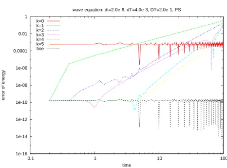
Taking into account the variants of the parareal in time algorithm introduced in [7] to simulate Hamiltonian systems we infer that the bad behavior of the parareal scheme comes from the non preservation of the invariant quantities. Let us for example observe the evolution of the value of the quantity H defined in (3.9)
1e-10 1e-08 1e-06 0.0001 0.01 1 100 0.1 1 10 100
error of solution, exact one: dt=2.0e-7
time
wave equation: dt=2.0e-6, dT=4.0e-3, DT=2.0e-1, PS k=7 k=8 k=9 k=11 k=13 k=15 fine
Fig. 3.4. Error on the solution obtained by the parareal method(δt = 2.10−6, dT =
4.10−3,∆T = 2.10−1)
The figures 3.5 and 3.6 illustrate the lack of conservation, that is coherent with the divergence of the scheme in this case.
Finally we want to notice that we have performed the same simulation with a Ricker pulse of varying force (by modifying the value of fs). The instability starts
much earlier for larger fs confirming the relation between the instability and the
singularity of the solution.
3.4. Parareal algorithm with projection. Let us define the manifold M corresponding to the set of all functions v such that H(v) = H(u(0)). The Standard Projection Method on M (see chapter 4 of [13]) can be written as follows: For a given ˜
u, solve the system in (u, λ)
u= eu+ λ∇H(eu), where λ ∈ R is such that H(u) = H(u(0)), i.e.
H(eu+ λ∇H(eu)) = H(u(0)). (3.14) We then set
u= πM(eu) (3.15)
In the general case, equation (3.14) can only be solved by some iterative method, for example, Newton iterations, but in the current case, using the fact that H is quadratic, we notice and take into account that equation (3.14) is a second order polynomial in λ that can be solved exactly.
1e-16 1e-14 1e-12 1e-10 1e-08 1e-06 0.0001 0.01 1 0.1 1 10 100 error of energy time
wave equation: dt=2.0e-6, dT=4.0e-3, DT=2.0e-1, PS k=0 k=1 k=2 k=3 k=4 k=5 fine
Fig. 3.5. Error on the energy obtained by the parareal method(δt = 2.10−6, dT= 4.10−3,∆T =
2.10−1) 1e-16 1e-14 1e-12 1e-10 1e-08 1e-06 0.0001 0.01 1 100 10000 0.1 1 10 100 error of energy time
wave equation: dt=2.0e-6, dT=4.0e-3, DT=2.0e-1, PS k=7 k=8 k=9 k=11 k=13 k=15 fine
Fig. 3.6. Error on the energy obtained by the parareal method(δt = 2.10−6, dT= 4.10−3,∆T =
2.10−1)
above, we obtain the parareal method with projection to M: u0n+1 = G∆T(u0n) ˜ uk+1n+1 = G∆T(uk+1n ) + F∆T(ukn) − G∆T(ukn), uk+1n+1 = πM(˜uk+1n+1). (3.16)
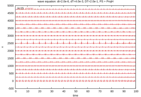
We now show the results obtained by parareal method with projection. We first note on figure 3.7 that the global solution after k = 15 iterations does not seem to present the instabilities of the plain parareal in time algorithm. The same conclusion holds after 25 iterations.
-500 0 500 1000 1500 2000 2500 3000 3500 4000 4500 5000 0 10 20 30 40 50 60 70 80 90 100 x time
wave equation: dt=2.0e-6, dT=4.0e-3, DT=2.0e-1, PS + ProjH k=15
Fig. 3.7. Vibration at different positions obtained by the parareal method with projection to the manifold M (δt = 2.10−6, dT= 4.10−3,∆T = 2.10−1)
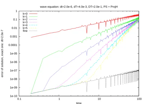
This is confirmed by the figures 3.8 and 3.9 where we note an improvement in the error between the exact solution and the discrete one as the iterations evolve. The error is always at worse of the same order as the error of the coarse propagator.
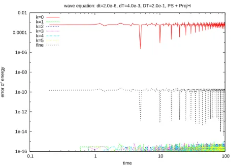
Of course this is far from being what is expected, but the conservation of H does improve the behavior of the algorithm. The following figures 3.10 and 3.11 illustrate the good preservation of H along the trajectory for the parareal method with projection. Although the solution does not diverge as in the plain parareal case, it does not converge as we would like.
In the results above, when doing the projection, we view all the Fourier modes as a whole system, and treat them altogether, with a unique Lagrange multiplier. Remember that each Fourier coefficient individually has an energy that is preserved as is explained in Remark 2. Instead of projecting on the manifold M, where only one invariant is taken into account, we can have a manifold defined with more invariant properties. We have defined only two invariants based on two groups in the Fourier coefficients, those corresponding to high wave numbers and those corresponding to low wave numbers. That is, we partition all the Fourier modes into two groups, one contains the modes |k| ≥ K0, the other one contains all the modes |k| < K0, we
then perform a projection for each group separately to make the energy of each group conserved.
The motivation comes from the fact that, when we discretize the solution by Fourier series, the contribution of the high frequency modes is much smaller than that of the low frequency modes. If we use the same Lagrange multiplier λ to correct
1e-10 1e-09 1e-08 1e-07 1e-06 1e-05 0.0001 0.001 0.01 0.1 1 0.1 1 10 100
error of solution, exact one: dt=2.0e-7
time
wave equation: dt=2.0e-6, dT=4.0e-3, DT=2.0e-1, PS + ProjH k=0 k=1 k=2 k=3 k=4 k=5 fine
Fig. 3.8. Error on the solution obtained by the parareal method with projection to the manifold M(δt = 2.10−6, dT= 4.10−3,∆T = 2.10−1) 1e-10 1e-09 1e-08 1e-07 1e-06 1e-05 0.0001 0.001 0.01 0.1 1 0.1 1 10 100
error of solution, exact one: dt=2.0e-7
time
wave equation: dt=2.0e-6, dT=4.0e-3, DT=2.0e-1, PS + ProjH k=7 k=8 k=9 k=11 k=13 k=15 fine
Fig. 3.9. Error on the solution obtained by parareal method with projection to the manifold M (δt = 2.10−6, dT= 4.10−3,∆T = 2.10−1)
all the modes, the contribution of the high frequency modes may be to magnify them and pollute the solution.
So, let us introduce two Lagrange multipliers λ1 and λ2, one is for the high
1e-16 1e-14 1e-12 1e-10 1e-08 1e-06 0.0001 0.01 0.1 1 10 100 error of energy time
wave equation: dt=2.0e-6, dT=4.0e-3, DT=2.0e-1, PS + ProjH k=0 k=1 k=2 k=3 k=4 k=5 fine
Fig. 3.10. Error on the energy obtained by parareal method with projection to the manifold M (δt = 2.10−6, dT= 4.10−3,∆T = 2.10−1) 1e-16 1e-15 1e-14 1e-13 1e-12 1e-11 1e-10 1e-09 0.1 1 10 100 error of energy time
wave equation: dt=2.0e-6, dT=4.0e-3, DT=2.0e-1, PS + ProjH k=7 k=8 k=9 k=11 k=13 k=15 fine
Fig. 3.11. Error on energy obtained by parareal method with projection to the manifold M (δt = 2.10−6, dT= 4.10−3,∆T = 2.10−1)
The method is not more complex to implement. The numerical simulation still with the same N = 30 is based on K0= 20; the results are much improved as can be
seen on figures 3.12, 3.13 and 3.14.
1e-10 1e-08 1e-06 0.0001 0.01 1 0.1 1 10 100
error of solution, exact one: dt=2.0e-7
time
wave equation: dt=2.0e-6, dT=4.0e-3, DT=2.0e-1, PS + ProjH, 2 groups k=0 k=1 k=2 k=3 k=4 k=5 fine
Fig. 3.12. Error on the solution obtained by the parareal with projection on two groups (δt = 2.10−6, dT= 4.10−3,∆T = 2.10−1) 1e-10 1e-08 1e-06 0.0001 0.01 1 0.1 1 10 100
error of solution, exact one: dt=2.0e-7
time
wave equation: dt=2.0e-6, dT=4.0e-3, DT=2.0e-1, PS + ProjH, 2 groups k=7 k=8 k=9 k=11 k=13 k=15 fine
Fig. 3.13. Error on the solution obtained by the parareal with projection on two groups (δt = 2.10−6, dT= 4.10−3,∆T = 2.10−1)
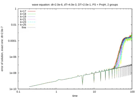
fine approximation as can be seen on figure 3.15.
For the linear second order wave equation, the preservation of the invariant quan-tities based on the decomposition of the coefficients representing the solution into two groups: the low modes and high frequency modes, is thus a sufficiently mild
1e-10 1e-08 1e-06 0.0001 0.01 1 0.1 1 10 100
error of solution, exact one: dt=2.0e-7
time
wave equation: dt=2.0e-6, dT=4.0e-3, DT=2.0e-1, PS + ProjH, 2 groups k=17 k=18 k=19 k=21 k=23 k=25 fine
Fig. 3.14. Error on the solution obtained by the parareal with projection on two groups (δt = 2.10−6, dT= 4.10−3,∆T = 2.10−1) -500 0 500 1000 1500 2000 2500 3000 3500 4000 4500 5000 0 10 20 30 40 50 60 70 80 90 100 x time
wave equation: dt=2.0e-6, dT=4.0e-3, DT=2.0e-1, PS + ProjH, 2 groups k=15
Fig. 3.15. Vibration at different positions obtained by parareal method with projection on two groups (δt = 2.10−6, dT= 4.10−3,∆T = 2.10−1)
ent to improve the behavior of the parareal in time algorithm. In the next section we shall extend this variant of the parareal in time algorithm to a nonlinear PDE.
Note that, if when the method converges, i.e. ∀n = 1, .., N , uk
solution satisfies thanks to (3.16)
u∞n+1= πM(F∆T(u∞n ))
that, here, due to the fact that the propagator F∆T is symplectic and thus preserves
the Hamiltonian, reads
u∞n+1= F∆T(u∞n)
that proves that the method converges towards the fine solution, as expected. 4. Burgers equation.
4.1. The total Fourier/time splitting discretization. Let us consider in this section the following periodic viscous Burgers’ equation in one dimension
∂u ∂t − ν ∂2u ∂x2+ 1 2 ∂(u2) ∂x = 0, (4.1) u(x, 0) = u0(x), u(x + T, t) = u(x, t),
The viscosity ν > 0 is planned to be very small so that the solution will exhibit very sharp gradients.
Taking into account that the periodic frame of the problem allows to use Fourier spectral approximation, we thus consider a semi discretization based on the Galerkin Fourier approximation in SN (∂uN ∂t , vN) + ν( ∂uN ∂x , ∂vN ∂x ) + 1 2( ∂(uN)2 ∂x , vN) = 0, ∀vN ∈ SN. (4.2) We then choose to use a second order symmetrized splitting method based on the splitting between the diffusion effects (treated in the Fourier space exactly) and the nonlinear convection effects (treated in the physical space). The only difference be-tween the coarse propagator G and fine propagator F are relative to the time steps dT and fine time step δt, respectively. Denoting by δ either dT or δt, the splitting schemes at each iteration proceeds as follows:
1. Solve the following problem in Fourier space in the interval [τn= nδ, τn+1 2 = τn+δ2] (∂uN ∂t , vN) + ν( ∂uN ∂x , ∂vN ∂x ) = 0, ∀vN ∈ SN (4.3) uN(τn) = uN,n, (4.4) and denote ˜uN,n+1
2 = uN(τn+12). Note that, as in the discretization of the
wave equation, by choosing iteratively vN = eik
2π
Tx, k ∈ [−N, N ], this results
in a system of differential equations in the Fourier coefficients. 2. Solve the following problem in [τn, τn+1]
(∂uN ∂t , vN) + 1 2( ∂(uN)2 ∂x , vN) = 0, ∀vN ∈ SN (4.5) uN(τn) = ˜uN,n+1 2, (4.6) and denote uN(τn+1) as uN,n+1
2. Note that here, the solution procedure
cannot be exact since the problem is non linear: the discretization in time is based on a 3rd order Runge Kutta method and an exact evaluation of the
Fourier coefficients of ∂(uN)2
3. Solve the following problem in Fourier space in [τn+1 2, τn+1] (∂uN ∂t , vN) + ν( ∂uN ∂x , ∂vN ∂x ) = 0, ∀vN ∈ SN (4.7) uN(τn+1 2) = uN,n+12. (4.8)
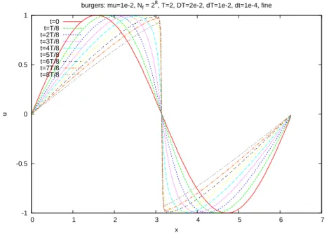
4.2. Results for the plain parareal in time algorithm. We have performed 3 tests for the plain algorithm. First we note that, provided that the viscosity is large enough, the parareal in time algorithm is working fine. Indeed in case referred later as Case 1, we have chosen
Case 1: 1. µ = 1e − 2, 2. Nc= 28, Nf = 28,
3. T = 2, ∆T = 2.10−2, dT = 1.10−2, δt= 1.10−4
The evolution is presented on figure 4.1, the relative error in the solution with respect to a solution computed with a much smaller time step is presented on figure 4.2 showing that after 3 parareal iterations, the same convergence as for the fine sequential simulation is achieved.
-1 -0.5 0 0.5 1 0 1 2 3 4 5 6 7 u x
burgers: mu=1e-2, Nf = 28, T=2, DT=2e-2, dT=1e-2, dt=1e-4, fine
t=0 t=T/8 t=2T/8 t=3T/8 t=4T/8 t=5T/8 t=6T/8 t=7T/8 t=8T/8
Fig. 4.1. Case 1: solution obtained by the parareal method(δt = 1e − 4, dT = 1e − 2, DT = 2e − 2)
For the second test, we have diminished the value of the viscosity. This case, referred to as Case 2, corresponds to the choices
Case 2: 1. µ = 1e − 3; 2. Nc= 29, Nf = 29,
1e-13 1e-12 1e-11 1e-10 1e-09 1e-08 1e-07 1e-06 1e-05 0.0001 0.001 0.01 0.01 0.1 1 10
relative error of solution, exact one: dt=1.0e-5
time
Burgers: mu=1e-2, Nc = 28, Nf = 28, dt=1.0e-4, dT=1.0e-2, DT=2.0e-2, PS
k=0 k=1 k=2 k=3 k=4 fine
Fig. 4.2. Case 1: relative error on the solution obtained by the parareal method(δt = 1e−4, dT = 1e − 2, DT = 2e − 2) 1e-15 1e-10 1e-05 1 100000 1e+10 1e+15 0.01 0.1 1 10
relative error of solution, exact one: dt=1.0e-6
time
Burgers: mu=1.0e-3, Nc=29, Nf=29, dt=1.0e-5, dT=1.0e-2, DT=2.0e-2, PS
k=0 k=1 k=2 k=3 k=4 k=5 fine
Fig. 4.3. Case 2-2: relative error of the solution obtained by the parareal method(δt = 1e − 5, dT = 1e − 2, ∆T = 2e − 2)
For this case, the plain parareal method is not stable, as can be seen on the figure 4.3, after 3 iterations instabilities occur soon after time 1 where the solution of the inviscid Burgers equation becomes discontinuous.
It should be noted that, as explained in [17], that using a coarser spacial repre-sentation helps in the stabilization of the process. Indeed, Case 3 below provides a stable parareal approximation
Case 3: 1. µ = 1e − 3; 2. Nc= 28, Nf = 29,
3. T = 2, ∆T = 2.10−2, dT = 1.10−2, δt= 1.10−5.
As can be seen on the series of figures 4.4, 4.5 and 4.6, the method is stable, converges but very slowly.
1e-14 1e-12 1e-10 1e-08 1e-06 0.0001 0.01 1 0.01 0.1 1 10
relative error of solution, exact one: dt=1.0e-6
time Burgers: mu=1e-3, Nc = 2
8
, Nf = 2 9
, dt=1.0e-5, dT=1.0e-2, DT=2.0e-2, PS k=0 k=1 k=2 k=3 k=4 k=5 k=6 fine
Fig. 4.4. Case 2-1: relative error of the solution obtained by the parareal method(δt = 1e − 5, dT = 1e − 2, DT = 2e − 2)
In the next sections, we shall improve the two last simulations by extending the method presented in the previous section.
4.3. Results for the plain parareal in time algorithm with projection alone. To start with, let us notice that, due to dissipation, there is no quantity that is preserved along a trajectory, nevertheless, by using uN as a test function in (4.2),
we derive that ∥uN(t)∥2L2(0,T)+ 2ν ∫ t 0 [∂uN ∂x ] 2= ∥u N(0)∥2L2(0,T),
and actually for any two times Tn+1> Tn≥ 0
∥uN(Tn+1)∥2L2(0,T)+ 2ν ∫ Tn+1 Tn [∂uN ∂x ] 2= ∥u N(Tn)∥2L2(0,T). (4.9)
In the parareal in time algorithm, starting from uk+1
n (remember that this represents
the Galerkin approximation that should be denoted as uk+1N,n), we expect that ∥uk+1n+1∥L2(0,T)= ∥F∆T[uk+1n ]∥L2(0,T) (4.10)
1e-14 1e-12 1e-10 1e-08 1e-06 0.0001 0.01 1 0.01 0.1 1 10
relative error of solution, exact one: dt=1.0e-6
time
Burgers: mu=1e-3, Nc = 28, Nf = 29, dt=1.0e-5, dT=1.0e-2, DT=2.0e-2, PS
k=7 k=8 k=9 k=11 k=13 k=15 fine
Fig. 4.5. Case 2-1: relative error of the solution obtained by the parareal method(δt = 1e − 5, dT = 1e − 2, DT = 2e − 2) 1e-14 1e-12 1e-10 1e-08 1e-06 0.0001 0.01 1 0.01 0.1 1 10
relative error of solution, exact one: dt=1.0e-6
time Burgers: mu=1e-3, Nc = 2
8
, Nf = 2 9
, dt=1.0e-5, dT=1.0e-2, DT=2.0e-2, PS k=17 k=18 k=19 k=20 k=23 k=25 fine
Fig. 4.6. Case 2-1: relative error of the solution obtained by the parareal method(δt = 1e − 5, dT = 1e − 2, DT = 2e − 2)
Since we do not want to compute F∆T[uk+1n ] at this stage, we approximate ∥F∆T[uk+1n ]∥L2(0,T)
by ∥F∆T[uk+1n ]∥L2(0,T)≃ ∥F∆T[ukn]∥L2(0,T) ∥uk n∥L2(0,T) ∥uk+1n ∥L2(0,T). (4.11)
What can thus be done is to consider the manifold Mk+1
n corresponding to the
set of all functions v such that ∥v∥L2(0,T)=
∥F∆T[ukn]∥L2(0,T)
∥uk
n∥L2(0,T) ∥u
k+1 n ∥L2(0,T)
Second, we have noticed in the analysis of the wave equation that treating all the frequencies with a unique Lagrange multiplier is not effective enough. We thus partition the frequency space of functions in SN into two (or more if necessary) groups
Gi, i = 1, 2 (or i = 1, .., I) defined by Gi= span{eiℓ 2π Tx, N− i ≤ |ℓ| < N + i }, (4.12) where L−1 = 0, 0 < L+1 = L−2 − 1, L2+ = N + 1 (or L−1 = 0, 0 < L+1 = L−2 − 1,
L−i < L+i = L−i+1+ 1, L+I = N + 1 if more groups are around). The L2–projection on
group Gi is denoted as Pi. In this case we consider the manifold [MI]k+1n defined as
being the intersection
[MI]k+1n = ∩Ii=1[mi]k+1n (4.13)
where the group manifolds [mi]k+1
n are defined as follows .
[mi]k+1 n = {v ∈ SN,∥Pi(v)∥L2(0,T)= ∥Pi[F∆T[ukn]]∥L2(0,T) ∥uk n∥L2(0,T) ∥uk+1 n ∥L2(0,T)} (4.14)
To any given ˜v ∈ SN, we associate the element π[MI]k+1
n (˜v) defined by the
Stan-dard Projection Method on [MI]k+1
n , that involves the determination of I Lagrange
multipliers.
With this manifold the parareal scheme with projection reads u0 n+1 = G∆T(u0n) ˜ uk+1n+1 = G∆T(uk+1n ) + F∆T(ukn) − G∆T(ukn), uk+1n+1 = π[MI]k+1 n (˜u k+1 n+1). (4.15)
The results are as follows (see figures 4.7, 4.8, 4.9). We notice that the parareal in time algorithm is stabilized, but it does not converge much. Increasing the number of groups does not improve the behavior of this variant of the parareal in time algorithm. Remark 3. If we would know the exact value of the energy of each groups, the projection method would converge. The problem of course is that due to dissipation, and also to nonlinear effect that mixes up the low and high frequencies, the value of the exact energy in each groups is not known. This is the reason why we get into these difficulties.
4.4. Results for the plain parareal in time algorithm with projection and damping. We notice that, for this non linear problem, the projection allows to stabilize the parareal in time algorithm but a little more is required. We have chosen to damp the high frequencies at each coarse step before proceeding to the next parareal iteration. This means that we introduce a damping function Φ that, to any element vN in SN provides an element wN = Φ(vN) in SN, such that
∀ℓ ∈ G1, wˆℓ= ˆvℓ (4.16)
∀ℓ ∈ Gi, i= 2, ..I, wˆℓ= f (i)ˆvℓ (4.17)
where f (i) is chosen such that high frequency parts are more and more filtered. In all the following results, we choose f (i) = 1
1e-14 1e-12 1e-10 1e-08 1e-06 0.0001 0.01 1 0.01 0.1 1 10
relative error of solution, exact one: dt=1.0e-6
time
Burgers: mu=1.0e-3, Nc=29, Nf=29, dt=1.0e-5, dT=1.0e-2, DT=2.0e-2, PS + ProjH, 2 groups
k=0 k=1 k=2 k=3 k=4 k=5 fine
Fig. 4.7. Case 2-2: relative error of the solution obtained by the method parareal with projection to 2 groups(δt = 1e − 5, dT = 1e − 2, DT = 2e − 2) 1e-14 1e-12 1e-10 1e-08 1e-06 0.0001 0.01 1 0.01 0.1 1 10
relative error of solution, exact one: dt=1.0e-6
time
Burgers: mu=1.0e-3, Nc=29, Nf=29, dt=1.0e-5, dT=1.0e-2, DT=2.0e-2, PS + ProjH, 2 groups
k=7 k=8 k=9 k=11 k=13 k=15 fine
Fig. 4.8. Case 2-2: relative error of the solution obtained by the method parareal with projection to 2 groups(δt = 1e − 5, dT = 1e − 2, DT = 2e − 2)
f(i) = 1
1e-14 1e-12 1e-10 1e-08 1e-06 0.0001 0.01 1 0.01 0.1 1 10
relative error of solution, exact one: dt=1.0e-6
time
Burgers: mu=1.0e-3, Nc=29, Nf=29, dt=1.0e-5, dT=1.0e-2, DT=2.0e-2, PS + ProjH, 2 groups
k=17 k=18 k=19 k=21 k=23 k=25 fine
Fig. 4.9. Case 2-2: relative error of the solution obtained by the method parareal with projection to 2 groups(δt = 1e − 5, dT = 1e − 2, DT = 2e − 2)
scheme with projection and damping reads u0n+1 = G∆T(u0n) ˜ uk+1n+1 = G∆T(¯uk+1n ) + F∆T(ukn) − G∆T(¯ukn), uk+1n+1 = π[MI]k+1 n (˜u k+1 n+1) ¯ uk+1n+1 = Φ(uk+1n+1). (4.18)
The following figures 4.10, 4.11 and 4.11 present the results of this improved parareal method. We notice that the parareal method is now converging.
Remark 4. Note that the strategy used here consisting in adding a little bit of dissipation on the high modes to the parareal scheme goes in the direction suggested in [2] and is coherent with the spectral viscosity proposed in [22]. Note also that the solution should be measured after the projection and before the damping. Note finally that the fine propagator acts on the undamped solution so that the dissipativity that is added does not affect the quality of the solution (e.g. as any parareal scheme, after Nth iterations, the solution is the same as the one of the plain fine propagator) but
improves the quality of the scheme.
The projection with more than two groups performs slightly better, see e.g. figure 4.13 where only the results for iterations between 7 and 15 are presented. It may be interesting to keep this in mind even though the separation in more than two groups is not completely straightforward in the non periodic case where finite difference, finite differences or finite volume techniques will be used.
5. Preliminary analysis. In this section, we provide some simple elements of analysis that prove the stabilty of the previous approximation with the parareal method with projection (and damping).
1e-14 1e-12 1e-10 1e-08 1e-06 0.0001 0.01 1 0.01 0.1 1 10
relative error of solution, exact one: dt=1.0e-6
time
Burgers: mu=1.0e-3, Nc=29, Nf=29, dt=1.0e-5, dT=1.0e-2, DT=2.0e-2, PS + ProjH + Damp, 2 groups
k=0 k=1 k=2 k=3 k=4 k=5 fine
Fig. 4.10. Case 2-2: relative error of the solution obtained by the method parareal with projec-tion to 2 groups with damping(δt = 1e − 5, dT = 1e − 2, DT = 2e − 2)
1e-14 1e-12 1e-10 1e-08 1e-06 0.0001 0.01 1 0.01 0.1 1 10
relative error of solution, exact one: dt=1.0e-6
time
Burgers: mu=1.0e-3, Nc=29, Nf=29, dt=1.0e-5, dT=1.0e-2, DT=2.0e-2, PS + ProjH + Damp, 2 groups
k=7 k=8 k=9 k=11 k=13 k=15 fine
Fig. 4.11. Case 2-2: relative error of the solution obtained by the method parareal with projec-tion to 2 groups with damping(δt = 1e − 5, dT = 1e − 2, DT = 2e − 2)
exists a constant α > 0 independent of the discretization parameters such that, ∀v ∈ L2(0, T), ∥F∆T(v)∥L2(0,T)≤ (1 + α∆T )∥v∥L2(0,T) (5.1)
1e-14 1e-12 1e-10 1e-08 1e-06 0.0001 0.01 1 0.01 0.1 1 10
relative error of solution, exact one: dt=1.0e-6
time
Burgers: mu=1.0e-3, Nc=29, Nf=29, dt=1.0e-5, dT=1.0e-2, DT=2.0e-2, PS + ProjH + Damp, 2 groups
k=17 k=18 k=19 k=21 k=23 fine
Fig. 4.12. Case 2-2: relative error of the solution obtained by the method parareal with projec-tion to 2 groups with damping(δt = 1e − 5, dT = 1e − 2, DT = 2e − 2)
1e-14 1e-12 1e-10 1e-08 1e-06 0.0001 0.01 1 0.01 0.1 1 10
relative error of solution, exact one: dt=1.0e-6
time Burgers: mu=1.0e-3, Nc=2
9
, Nf=2 9
, dt=1.0e-5, dT=1.0e-2, DT=2.0e-2, PS + ProjH + Damp, 10 groups k=7 k=8 k=9 k=11 k=13 k=15 fine
Fig. 4.13. Case 2-2: relative error of the solution obtained by the method parareal with projec-tion to 10 groups with damping(δt = 1e − 5, dT = 1e − 2, DT = 2e − 2)
inequality holds with α = 0.
1e-14 1e-12 1e-10 1e-08 1e-06 0.0001 0.01 1 0.01 0.1 1 10
relative error of solution, exact one: dt=1.0e-6
time
Burgers: mu=1.0e-3, Nc=29, Nf=29, dt=1.0e-5, dT=1.0e-2, DT=2.0e-2, PS + ProjH + Damp, 10 groups
k=17 k=18 k=19 fine
Fig. 4.14. Case 2-2: relative error of the solution obtained by the method parareal with projec-tion to 10 groups with damping(δt = 1e − 5, dT = 1e − 2, DT = 2e − 2)
we derive ∥uk+1n+1= π[MI]k+1 n (eu k+1 n+1)∥2L2(0,T)= I ∑ i=1 ∥Pi[uk+1n+1]∥2L2(0,T) = I ∑ i=1 ∥Pi[F∆T[ukn]]∥2L2(0,T) ∥uk n∥2L2(0,T) ∥uk+1n ∥2L2(0,T) = ∥F∆T[u k n]∥2L2(0,T) ∥uk n∥2L2(0,T) ∥uk+1n ∥2L2(0,T) ≤ (1 + α∆T )2∥uk+1 n ∥2L2(0,T) (5.2)
This proves the stability by induction
∥uk+1n+1∥L2(0,T)≤ (1 + α∆T )n+1∥uk+10 = u0∥L2(0,T)
≤ eαT∥u
0∥L2(0,T) (5.3)
6. Concluding remarks. In this paper we have analyzed and proposed a cure to the lack of robustness of the parareal in time algorithm applied to hyperbolic systems or convection diffusion problems with small diffusion. The lack of robustness, leading sometimes to instabilities of the algorithm before convergence is a consequence of the lack of regularity that the solution develops when time runs. The cure is inherited from the extension of the parareal in time algorithm for Hamiltonian system and consists in projecting the solution over an energy manifold defined on the fly, and improved iteratively, where the exact solution lies. This simple procedure allows to stabilizes the algorithm that now converges after some iterations. It should be noted that, similarly as for other types of equations, the convergence of the parareal in time algorithm allows to speed up the solution procedure but is not optimal in terms of
parallel efficiency since, roughly speaking, a convergence that is achieved after 10 or 15 iterations leads to a parallel efficientcy of 1
10 or 1
15 at best, which is far from optimal.
It is not the purpose of this paper to provide a full optimal implementation of the approach. Let us just notice that the combination of the parareal in time algorithm with standard domain decomposition methods is a way to improve the efficiency and use more of the processors that are available on current architectures than the one that a plain domain decomposition technique is able to optimally use. We refer to [12] for more on this matter.
Acknowledgments. This work has been supported in part by the Agence Na-tionale de la Recherche, under the grant ANR-06-CIS6-007 (PITAC).
REFERENCES
[1] L. Baffico, S. Bernard, Y. Maday, G. Turinici, G. Z´erah, Parallel in time molecular dynamics simulations, Physical Review. E 66(2002)
[2] G. Bal , On the convergence and the stability of the parareal algorithm to solve partial differen-tial equations, In Domain Decomposition Methods in Science and Engineering, Kornhuber R, Hoppe RHW, Keyes DE, P´eriaux J, Pironneau O, Xu J (eds). Lecture Notes in Com-puter Science and Engineering, vol. 40. Springer: Berlin, 2004; 425432.
[3] G. Bal, Y. Maday, A ”parareal” time discretization for non-linear PDE’s with application to the pricing of an American put, in Recent Developments in domain Decomposition Methods, L. F. Pavarino, A. Toselli (eds), Lecture Notes in Computational Science and Engineering, 23, Springer, 189—202 (2002)
[4] K. Burrage, Parallel and sequential methods for ordinary differential equations, Numerical Mathematics and Scientific Computation, Oxford Science Publications, The Clarendon Press, Oxford University Press, New York, 1995.
[5] K. Burrage, Parallel methods for ODEs, Advances in Computational Mathematics 7(1-2), 1–3, 1997.
[6] F. Chouly and M. A. Fern´andez, An Enhanced parareal Algorithm for Partitioned Parabolic-Hyperbolic Coupling, AIP Conference Proceedings, 1168 1, pp 1517–1520, 2009. [7] X. Dai, C. Le Bris, F. Legoll, Y. Maday , parareal algorithms for Hamiltonian systems,
submitted to M2
AN
[8] C. Farhat, M. Chandesris , Time-decomposed parallel time-integratorspart I: theory and feasibility studies for fluid, structure, and fluidstructure applications, International Journal for Numerical Methods in Engineering 2003; 58(9):13971434.
[9] C. Farhat, J. Cortial, C. Dastillung, H. Bavestrello , Time-parallel implicit integra-tors for the near-real-time prediction of linear structural dynamic responses, International Journal for Numerical Methods in Engineering 2006; 67(5):697724.
[10] J. Cortial, C. Farhat , A time-parallel implicit method for accelerating the solution of non-linear structural dynamics problemsInternational, Journal for Numerical Methods in En-gineering 2009; 77 :451470.
[11] P. F. Fischer, F. Hecht, and Y. Maday. , A parareal in time semi-implicit approximation of the navier-stokes equations, In Domain decomposition methods in science and engineering, volume 40 of Lect. Notes in Comput. Sci. Eng., pages 433440. Springer, Berlin, 2005. [12] R. Guetat. , Mthode de parall´elisation en temps : Application aux m´ethodes de d´ecomposition
de domaine PhD Thesis, UPMC Paris 2011.
[13] E. Hairer, C. Lubich, and G. Wanner, Geometric numerical integration: structure-preserving algorithms for ordinary differential equations, ??
[14] J.-L. Lions, Y. Maday, G. Turinici , R´esolution d’EDP par un sch´ema en temps “parar´eel”, Comptes Rendus de l’Acad´emie des Sciences de Paris — S´erie I — Math´ematique 2001; 332(7):661—668.
[15] Y. Liu, and J. Hu,, Modified propagators of parareal in time algorithm and application to Princeton Ocean model, International Journal for Numerical Methods in Fluids, 57: 17931804. (2008).
[16] Y. Maday. , parareal in time algorithm for kinetic systems based on model reduction, In High dimensional partial differential equations in science and engineering, 41 CRM Proc. Lecture Notes, pages 183 — 194. Amer. Math. Soc., Providence, RI, 2007.
[17] Y. Maday. , The “parareal in time” algorithm, In Sub-Structuring Techniques and Domain Decomposition Methods, 24 Computational Science, Engineering & Technology Series, pages 19—44. Saxe-Coburg Publications, 2010.
[18] Y. Maday, G. Turinici , A parareal in time procedure for the control of partial differential equations C.R.Acad Sci. Paris S´er. I Math 335 387—392 (2002)
[19] D. Mercerat and L.Guillot and J.-P. Vilotte , Application of the parareal Algorithm for Acoustic Wave Propagation, AIP Conference Proceedings, 1168 1, pp 1521–1524, 2009. [20] J. Nievergelt. , Parallel methods for integrating ordinary differential equations, Commun.
ACM, 7(12):731—733, 1964.
[21] G. Staff and E. Rønquist , Stability of the parareal Algorithm In Domain decomposition methods in science and engineering, volume 40 of Lect. Notes in Comput. Sci. Eng., pages 449—456. Springer, Berlin, 2005.
[22] E. Tadmor, Convergence of Spectral Methods for Nonlinear Conservation Laws, SIAM Journal on Numerical Analysis Vol. 26, No. 1 (Feb., 1989), pp. 30-44

![[PDF] Elaboration d’algorithmes itératifs en PDF | Cours informatique](data:image/gif;base64,R0lGODlhAQABAIAAAP///wAAACH5BAEAAAAALAAAAAABAAEAAAICRAEAOw==)