Publisher’s version / Version de l'éditeur:
Vous avez des questions? Nous pouvons vous aider. Pour communiquer directement avec un auteur, consultez la première page de la revue dans laquelle son article a été publié afin de trouver ses coordonnées. Si vous n’arrivez pas à les repérer, communiquez avec nous à PublicationsArchive-ArchivesPublications@nrc-cnrc.gc.ca. Questions? Contact the NRC Publications Archive team at
PublicationsArchive-ArchivesPublications@nrc-cnrc.gc.ca. If you wish to email the authors directly, please see the first page of the publication for their contact information.
https://publications-cnrc.canada.ca/fra/droits
L’accès à ce site Web et l’utilisation de son contenu sont assujettis aux conditions présentées dans le site
LISEZ CES CONDITIONS ATTENTIVEMENT AVANT D’UTILISER CE SITE WEB.
30th Annual Meeting of the Adhesion Society 2007 [Proceedings], 2006-01-01
READ THESE TERMS AND CONDITIONS CAREFULLY BEFORE USING THIS WEBSITE.
https://nrc-publications.canada.ca/eng/copyright
NRC Publications Archive Record / Notice des Archives des publications du CNRC :
https://nrc-publications.canada.ca/eng/view/object/?id=a9e6c8fe-91e7-4d10-a3eb-1a4ed0d7da61 https://publications-cnrc.canada.ca/fra/voir/objet/?id=a9e6c8fe-91e7-4d10-a3eb-1a4ed0d7da61
NRC Publications Archive
Archives des publications du CNRC
This publication could be one of several versions: author’s original, accepted manuscript or the publisher’s version. / La version de cette publication peut être l’une des suivantes : la version prépublication de l’auteur, la version acceptée du manuscrit ou la version de l’éditeur.
Access and use of this website and the material on it are subject to the Terms and Conditions set forth at
The effect of substrate material on the quasi-static measurement of
critical energy release rate in adhesive joints
Eskandarian, M.; Azari, S.; Papini, M.; Schroeder, J. A.; Faulkner, D. L.;
Spelt, J. K.
THE EFFECT OF SUBSTRATE MATERIAL ON THE QUASI-STATIC
MEASUREMENT OF CRITICAL ENERGY RELEASE RATE IN ADHESIVE JOINTS
M. Eskandarian
1, S. Azari
2, M. Papini
3, J.A. Schroeder
4, D.L. Faulkner
4, and J.K. Spelt
2*
1) Aluminium Technology Centre, Industrial Materials Institute, National Research Council Canada, 501 boul. de l'Univ.,
Chicoutimi, Québec, Canada G7H 8C3, mojtaba.eskandarian@cnrc-nrc.gc.ca
2) Department of Mechanical and Industrial Engineering, University of Toronto, 5 King’s College Road, Toronto, Ontario,
Canada M5S 3G8, spelt@mie.utoronto.ca
3) Department of Mechanical and Industrial Engineering, Ryerson University, 350 Victoria Street, Toronto, Ontario, Can-ada M5B 2K3
4) General Motors Research & Development and Planning, 30500 Mound Road, Warren, MI 48090-9055, USA
*
Corresponding AuthorIntroduction
An engineering approach to fracture load predictions for adhesive joints was presented in Refs. [1] and [2]. The concept of the adhesive sandwich, where the bonded over-lap is isolated from the surrounding structure as a free body, makes this approach applicable to a variety of joints including more practical joints like single-lap-shear (SLS) and cracked-lap-shear (CLS) joints. The dependence of the critical energy release rate (Gc) on the mode ratio, known
as the fracture envelope, is experimentally determined over a range of mode ratios using quasi-static fracture tests on double-cantilever-beam (DCB) specimens. The joint fail-ure will occur by crack propagation in the bondline when-ever the calculated energy release rate (G) in the practical joint exceeds Gc from the fracture envelope at the
corre-sponding mode ratio. The test results showed a good agreement with the model for aluminum adherends.
Recent results of quasi-static fracture tests on DCB specimens made of aluminum and steel revealed that Gc
appeared to depend on the substrate material and the thick-ness of the adherends. Bell and Kinloch [5] found the highest values of Gc associated with joints having stiffer
adherends; however, Yan et al. [6] reported that Gc was
lower for stiffer substrates. These observations were at-tributed to changes in the stress field ahead of the crack [5] and the degree of triaxiality of the stress state [6].
In this report, Gc was measured on aluminum and steel
DCB joints at different mode ratios. The results were con-sistent with Ref. [6] and the analysis of Ref. [7].
Experiments and Analysis
The DCB specimens were fabricated from aluminum 6061-T651, aluminum 7075-T651 and steel AISI 4140 flat bars (thickness 12.7 mm) bonded with a 0.4 mm thick layer of toughened epoxy adhesive. The aluminum parts were abraded, degreased and then surface pretreated while the steel parts were only abraded and degreased prior to bonding. Cohesive fracture through the adhesive layer was
observed in all the cases, so the value of Gc was not
af-fected by interfacial debonding. The adherends remained elastic. The specimens then were tested using the load jig of Ref. [3] at different mode ratios under displacement control. More details on sample preparation and test pro-cedure can be found in Refs. [1] - [4].
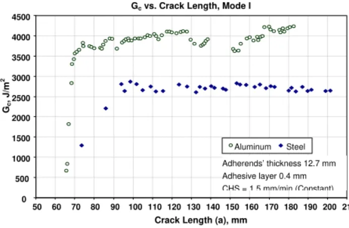
The typical R-curves of these DCB samples are shown in Fig. 1. The tests were conducted at a constant crosshead speed (CHS) of 1.5 mm/min where the load was gradually increased to the point of fracture. The maximum difference in measured values of Gc (30%) was observed for these
adhesive systems under mode I loading. The slope of the rising part of the R-curve reflects the crack propagation distance required to establish a fully developed damage zone. Hence, the development of the damage zone was faster in the aluminum DCB specimens.
Figure 1. R-curves measured for aluminum and steel DCBs in quasi-static tests.
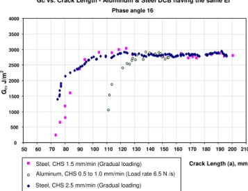
A second series of Gc measurements were made with
DCBs having different adherend materials but the same flexural rigidity. For a phase angle of 16º, the 18 mm thick steel and 12.7 mm thick aluminum specimens were tested at identical strain rates. Figure 2 shows that Gc in this case
was independent of material.
Gc vs. Crack Length, Mode I
0 500 1000 1500 2000 2500 3000 3500 4000 4500 50 60 70 80 90 100 110 120 130 140 150 160 170 180 190 200 210
Crack Length (a), mm
Gc , J/m 2 Aluminum Steel Adherends’ thickness 12.7 mm Adhesive layer 0.4 mm CHS = 1 5 mm/min (Constant)
Figure 2. Aluminum and steel DCB tests having similar rigidity tested at similar strain rates.
Strain rate in adhesive layer: It was observed that the
crack would grow with different velocities depending on the flexural rigidity of the bonded adherends. To evaluate the difference in strain rate around the crack-tip, aluminum and steel DCB specimens having the flexural rigidities of 12,200 and 35,000 N.m, respectively, were modeled using finite element analysis (FEA). A typical result is shown in Fig. 3 for the phase angle of 0º (mode I) and 51º with a crosshead speed of 1.5 mm/min. In this case, the adhesive layer of the stiffer steel DCB experiences twice the von-Mises strain rate of the aluminum specimen. Mode I strain rates are greater than those at 51º for both steel and alumi-num.
Based on the FEA results, another experiment was conducted to evaluate the effects of different crack veloci-ties on Gc for steel DCB specimens. For some of the tests,
the crosshead speed was maintained constant, while for others a variable crosshead speed was applied to keep the load rate constant over a range of crack lengths. The re-sults (Fig. 4) revealed a significant dependency of Gc on
the adhesive strain rate.
Mode ratio: The differences in Gc of aluminum and steel
DCBs decreased at higher phase angles (Fig. 5).
Figure 5. Fracture envelopes obtained from the quasi-static tests on aluminum and steel DCB specimens
Stress field and plastic zone: The stress field and the size of the plastic zone ahead of the crack depend on the joint geometry [5]. The FE models revealed that the stresses in the adhesive layer bounded by the stiffer adherends are more elevated. This could be the cause of the longer dam-age zone in steel DCB specimens (Fig. 1).
Degree of triaxiality of the stress state: 3D FE models
have been constructed to help understand the influence of constraint in the adhesive layer of DCBs made with steel and aluminum.
Phase angle (ψ), deg.
Fracture envelope - Bare steel vs Aluminum
2000 2500 3000 3500 4000 4500 5000 5500 6000 6500 7000 7500 8000 8500 0 10 20 30 40 50 60 Gc, J /m 2
AVG, Bare steel (CHS=1.5 mm/min)
AVG, Bare steel (Load rate=13 to 36 N/sec) AVG, Aluminum (CHS=1.5 mm/min)
Test results, Bare steel (Load rate=13 to 36 N/sec) Test results, Bare steel (CHS=1.5 mm/min)
Gc, AL = 3850.8 + 10.996 ψ − 0.9495 ψ2 + 0.0405 ψ3
Gc, ST = 2741.1 + 2.3384 ψ + 0.1423 ψ2 + 0.0250 ψ3
Strain-rate dependency of Gc, Steel DCB, Mode I
0 500 1000 1500 2000 2500 3000 3500 4000 40 50 60 70 80 90 100 110 120 130 140 150 160 170 180 190 200 210 220
Crack Length (a), mm
Gc
, J
/m
2
Figure 4. Strain-rate dependency of Gcmeasured with steel
DCBs
Steel, CHS 1.5, Load rate 36
Steel, Load rate 18, CHS 1.5 Steel, Load rate 18, CHS 4 Steel, Load rate 6.5, CHS 0.7 Steel, Load rate 6.5, CHS 1.5
Load rates in N/s, CHS in mm/min
Figure 3. Von-Mises strain rate in the adhesive layer of DCBs under mode I and at a phase angle of 51º.
Strain rate around crack tip vs. crack length - CHS 1.5 mm/min
Total time=300 s, Dtime = 15 s
0.0 0.5 1.0 1.5 2.0 2.5 3.0 50 60 70 80 90 100 110 120 130 140 150 160 170 180 190 200 210 Crack length, mm S train ra te x 1 0 4, 1/ s
Steel - 51 deg Aluminum - 51 deg Steel - mode I Aluminum - mode I
Gc vs. Crack Length - Aluminum & Steel DCB having the same EI
Phase angle 16 0 500 1000 1500 2000 2500 3000 3500 4000 50 60 70 80 90 100 110 120 130 140 150 160 170 180 190 200 210
Crack Length (a), mm
Steel, CHS 1.5 mm/min (Gradual loading)
Steel, CHS 2.5 mm/min (Gradual loading) Aluminum, CHS 0.5 to 1.0 mm/min (Load rate 6.5 N /s)
Gc
, J/m
Conclusion
The adherend thickness and its stiffness affect the stress field, plastic zone, degree of constraint, and strain rate in the adhesive layer of DCBs during fracture tests.
Acknowledgements
The authors wish to acknowledge the Natural Sciences and Engineering Research Council of Canada, Ontario Centers of Excellence, General Motors of Canada and the Aluminum Technology Centre of the National Research Council of Canada for their financial support.
References
1. G. Fernlund, M. Papini, D. McCammond and J.K. Spelt, Fracture load predictions for adhesive joints,
Compos. Sci. Technol., 1994, 51, pp. 587-600. 2. M. Papini, G. Fernlund and J.K. Spelt, Effect of
crack-growth mechanism on the prediction of fracture load of adhesive joints, Compos. Sci. Technol., 1994, 52, pp. 561-570.
3. G. Fernlund and. J.K. Spelt, Mixed-mode fracture characterization of adhesive joints, Compos. Sci.
Technol., 1994, 50, pp. 441-449.
4. M. Papini, G. Fernlund and J.K. Spelt, The effect of geometry on the fracture of adhesive joints, Int. J.
Ad-hes. AdAd-hes., 1994, 14, pp. 5-13.
5. A.J. Bell and A.J. Kinloch, The effect of the substrate material on the value of the adhesive fracture energy,
J. Mater. Sci. Lett., 1997, 16, pp. 1450-1453.
6. C. Yan, Y.-W. Mai, Q. Yuan, L. Ye and J. Sun, Ef-fects of substrate materials on fracture toughness measurements in adhesive joints, Int. J. Mech. Sci., 2001, 43, pp. 2091-2102.
7. S.S. Wang, An analysis of the crack tip stress field in DCB adhesive fracture specimens, Int. J. Fracture, 1978, 14, pp. 39-58.