Publisher’s version / Version de l'éditeur:
Vous avez des questions? Nous pouvons vous aider. Pour communiquer directement avec un auteur, consultez la première page de la revue dans laquelle son article a été publié afin de trouver ses coordonnées. Si vous n’arrivez pas à les repérer, communiquez avec nous à PublicationsArchive-ArchivesPublications@nrc-cnrc.gc.ca.
Questions? Contact the NRC Publications Archive team at
PublicationsArchive-ArchivesPublications@nrc-cnrc.gc.ca. If you wish to email the authors directly, please see the first page of the publication for their contact information.
https://publications-cnrc.canada.ca/fra/droits
L’accès à ce site Web et l’utilisation de son contenu sont assujettis aux conditions présentées dans le site LISEZ CES CONDITIONS ATTENTIVEMENT AVANT D’UTILISER CE SITE WEB.
NSTI Nanotechnology Conference 2007, 1, pp. 391-394, 2007-05-20
READ THESE TERMS AND CONDITIONS CAREFULLY BEFORE USING THIS WEBSITE. https://nrc-publications.canada.ca/eng/copyright
NRC Publications Archive Record / Notice des Archives des publications du CNRC :
https://nrc-publications.canada.ca/eng/view/object/?id=b6e1eb0b-9c3e-420a-a35d-b21ab90d534d https://publications-cnrc.canada.ca/fra/voir/objet/?id=b6e1eb0b-9c3e-420a-a35d-b21ab90d534d
NRC Publications Archive
Archives des publications du CNRC
This publication could be one of several versions: author’s original, accepted manuscript or the publisher’s version. / La version de cette publication peut être l’une des suivantes : la version prépublication de l’auteur, la version acceptée du manuscrit ou la version de l’éditeur.
Access and use of this website and the material on it are subject to the Terms and Conditions set forth at
Porous optical filter with spatially graded response
Porous optical filter with spatially graded response
Katie M. Krause, Matthew M. Hawkeye, Michael J. Brett
Department of Electrical and Computer Engineering
University of Alberta, Edmonton, Alberta, Canada, katiek@ualberta.ca
ABSTRACT
Glancing angle deposition was used to grow a spatially-graded thin film optical Rugate filter. The spatially-graded thickness of the rugate filter resulted in spatially varying spectral characteristics. The defect-induced transmittance peak location varied approximately 150nm across a 25mm length of film. This type of thin film will be useful as a position sensor. Because of its highly porous nature, micro-fluidic and microchromatographic devices are also possible. Keywords: rugate, porous, graded, optical, sensor
1 INTRODUCTION
Glancing angle deposition (GLAD) has become a common technique for producing thin films with various structural features [1]. Through physical vapour deposition at an oblique angle, self-shadowing is utilized to create nanocolumns of different architectures. In the current work, we have further modified GLAD in order to create porous structures that have spatially graded profiles, suitable for application in fluidic and sensor devices.
Various methods can be employed to create thin films with spatially graded profiles. A sliding mask can be used during sputtering [2,3], epitaxial [4], or chemical [5] deposition. Alternatively, the thin film thickness dependence on the distance, and angle of incidence, between the substrate and evaporant source can be exploited [6]. Our method takes advantage of the fact that with GLAD the substrate is kept at an oblique angle to the deposition source. As such, any object placed near the substrate will shadow it during the deposition. By employing substrate motion, the shadow’s area and duty cycle can be controlled, thus controlling the thickness gradient on the substrate.
To illustrate the usefulness of this macroscopic shadowing property, an optical rugate interference filter was grown using the GLAD shadowing method. Optical rugate filters have been demonstrated in the past, using the conventional GLAD deposition method [7,8], but all have had a uniform thickness and constant spectral profile across the substrate. Graded-thickness optical rugate filters have been created by [2] and [3], among others, but all have required a complex multiple step process to lay down the multiple layers required to generate the rugate filter. The advantage of using the GLAD process is that a spatially-graded rugate filter can be created in a single step.
During the single-step GLAD process, macroscopic shadowing was used to produce a film with a variation in thickness across its length. Conventional GLAD substrate motion was used, but at the centre of the substrate holder a large shadowing cylinder was placed. Figure 1 shows the substrate holder and shadow block used for this deposition.
Figure 1: Substrate holder and shadowing block used to create spatially graded thin film
2 BACKGROUND
A thin film rugate filter has a periodically varying refractive index profile. The resultant interference effects lead to a transmission stop band whose bandwidth depends on the pitch of the refractive index variation. The stop band center wavelength (λSB) depends on the average refractive index of the film (navg) and the pitch (p) [9].
p
n
avg2
=
λ
(1) When a defect, such as a phase shift or section of constant index, is introduced in the rugate structure a narrow transmittance peak emerges within the stopband [7].To create the spatially-graded rugate filter, the orientation of the substrate, relative to the source, was sinusoidally varied throughout the deposition. The oblique deposition angles employed, in tandem with self-shadowing, resulted in the growth of nanocolumns with periodically changing diameters. The shadowing cylinder caused the column heights to vary across the radial distance of the substrate, as illustrated in Figure 2.
Substrate Deposition Angle Deposition Vapour Flux at Oblique Angle Substrate Orientation Shadowing Cylinder Shadow Substrate Motion
Figure 2: Spatially-graded rugate filter with defect
3 RESULTS
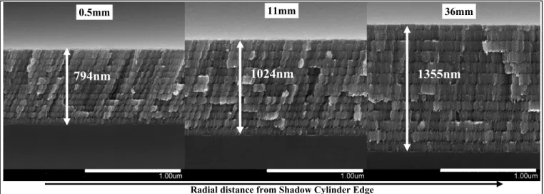
Spatially-graded titanium dioxide (Cerac, Inc., 99.9% pure) Rugate filters were fabricated on glass and silicon substrates using custom-built GLAD-equipped Kurt J. Lesker electron-beam physical vapour deposition systems. Scanning Electron Micscope (SEM) images of these Rugate films were taken using a Hitashi field emission S4800. Figure 3 shows the SEM images of a spatially-graded 12-turn Rugate filter grown using the macroscopic shadowing GLAD method. The periodicity of the nanocolumns is apparent in this figure. Also of note is the tilt of the columns towards the shadowing cylinder. This tilt is due to the fact that deposition flux can only impinge on the columns from a restricted range of deposition angles.
The thickness profiles of 12-turn Rugate films versus radial distance were taken from the SEM images. The thickness profiles are plotted, for two different shadowing cylinder heights, in Figure 4. The thickness of the thin film grown on top of the shadowing block is also plotted (as a dashed line). As the radial distance is increased the thickness grows until it reaches some maximum value. Because of the dependence of film thickness on substrate-source geometry the shadowed film does not quite reach the same final thickness as the top-of-cylinder film.
With a larger shadowing cylinder the shadow cast is longer and the thickness slope is more gradual. The height of the shadowing cylinder can therefore be used to tailor the thickness profile of the deposited thin film.
Figure 4: Increasing thickness of a spatially graded 12-turn Rugate thin film versus radial distance for a) a
20mm cylinder height, b) a 40mm cylinder height.
Defect
Wide layer, nHigh
Narrow, nLow
Distance from Shadowing Device Height of
Nanocolumn Nanocolumns with varying thicknesses (and thus varying indices of refraction)
1355nm
1024nm
794nm
36mm 0.5mm 11mmRadial distance from Shadow Cylinder Edge
The optical spectra for the different Rugate filters were obtained using an Ocean Optics HR4000 spectrometer. Figure 5 shows the transmittance profile obtained for the graded Rugate filter grown using the macroscopic shadowing GLAD method. This film is 12-turn Rugate filter, grown with a 40mm shadowing block.
Figure 5: Increase in stop-band and peak wavelength location with radial position (Peak at ~480nm 15mm from shadow block, ~500nm at 20mm, and ~510nm at
25mm) of a thin film 12-turn Rugate filter
Figure 6 shows the defect-induced transmittance peak location dependence on the radial position from the shadowing cylinder edge. This figure reveals a smooth and monotonic relationship between peak wavelength location and position. The peak location depends on radial distance from the shadow cylinder edge, as well as on the height of the shadowing cylinder. Comparison of Figure 6 to Figure 4 reveals that the peak location dependence on radial distance follows a similar trend as the thickness variation.
Figure 6: 12-turn Rugate film peak wavelength location as a function of radial distance from (20mm and 40mm
high) shadow cylinder edge
The relationship between the location of the peak wavelength and the thickness of the film is of interest. Figure 7 shows a plot of this relationship for a 12-turn film. The relationship is not a constant, indicating that the pitch or refractive index is not constant as a function of radial position. This behaviour is left for further investigation.
Figure 7: The non-constant ratio of peak wavelength location to thickness (for a 12turn film with 40mm shadowing cylinder) indicates that either the pitch or refractive index varies as a function of radial position
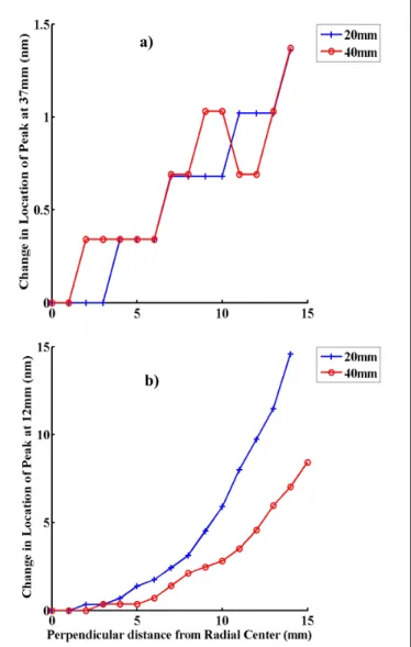
Of interest is whether there is a spectral dependence of the filter in only the radial direction. This concept is illustrated in Figure 8 and shown to not be the case in Figure 9. There is a spectral dependence in the normal direction as well, for radial distances close to the shadowing cylinder. As the radial position is increased the wavelength dependence becomes more constant across the normal direction.
Figure 8: Measuring spectral dependence graded Rugate filter normal to radial direction
Radial Direction 12mm 37mm Shadow Cylinder Substrates Normal Direction
Figure 9: Peak Wavelength location (plotted for two different shadowing cylinder sizes) depends strongly on distance normal to radial direction at positions close to the shadowing cylinder ( b) at 12mm), but less so farther away ( a) at 37mm)
This two-dimensional wavelength dependence on position could be taken advantage of in order to make a two-dimensional position sensor.
4 CONCLUSIONS
Porous thin films with spatially graded thickness have the potential to be quite useful in many applications. The graded Rugate filter illustrated in this paper has an immediate application as a position sensor, where the transmittance peak could be tracked to indicate changes in displacement. Most importantly however, is that we have fabricated a porous filter with spatially graded response which allows for impregnation of optically active materials,
liquids, and gases in order to provide a sensor device with advanced or specialized capabilities. Not only could porous graded Rugate filters be grown, but so could graded porous chiral films and photonic bandgap structures. Micro-fluidic and microchromatograph devices with spatially graded profiles are also possible.
REFERENCES
[1] K. Robbie, M.J. Brett, and A. Lakhtakia, "Chrial sculptured thin films,” Nature, 384, 616, 1996. [2] A. Piegari., “Variable narrowband transmission
filters with a wide rejection band for spectrometry,” Applied Optics, 45, 3768-3773, 2006.
[3] D.W. Dodds, I. Gershkovich, and B.T. Cunningham “Fabrication of a graded-wavelength guided-mode resonance filter photonic crystal,” Applied Physics Letters, 89, 123113-1 – 123113-3, 2006.
[4] B.S. Krusor, et. al., “Description and applications of a graded-thickness growth technique for molecular-beam epitaxy,” Journal of Vacuum Science Technology B, 8, 172-175, 1990.
[5] O. Wang, et. al., “Combinatorial Approach to Thin-Film Silicon Materials and Devices,” MRS Spring Meeting, Symposium A, 2003.
[6] A. Thelen., “Circularly Wedged Optical Coatings,” Applied Optics, 4, 977-985, 1965.
[7] A.C. van Popta et. al., “Gradient-index narrow-bandpass filter fabricated with glancing angle deposition,” Optics Letters, 29, 2545-2547, 2004. [8] M.M.Hawkeye, M.J. Brett, “Narrow bandpass
optical filters fabricated with one-dimensionally periodic inhomogeneous thin films,” Journal of Applied Physics, 100, 044322-1 - 044322-7, 2006. [9] B.G. Bovard, “Rugate filter theory: an overview,”
Applied Optics, 32, 5427-55442, 1993.
ACKNOWLEDGEMENTS
This research was supported by the Natural Sciences and Engineering Research Council (NSERC), the NRC National Institute for Nanotechnology, the Informatics Circle of Research Excellence (iCORE), and Micralyne Inc.
a)


