Augmented Manual Fabrication Methods for
2D Tool Positioning and 3D Sculpting
by
Alec Rivers
B.A., Cornell University (2007)
S.M., Massachusetts Institute of Technology (2010)
Submitted to the Department of
Electrical Engineering and Computer Science
in partial fulfillment of the requirements for the degree of
Doctor of Philosophy in Computer Science and Engineering
at the
MASSACHUSETTS INSTITUTE OF TECHNOLOGY
February 2013
®
Massachusetts Institute of Technology 2013.
All
rights reserved.
A uthor ...
.
...
.
Department of
Electrical Engineering and Computer Science
November 30th, 2012
Certified by...
.......
. . ... ...
Fre(do Durand
Professor
Thesis Supervisor
Accepted
by... ...
I
---DLesle iolodziejski
Chairman,
Departmenit
Comnmittee
on Graduate
Students
OARCMES
APR
0IES
Augmented Manual Fabrication Methods for
2D Tool Positioning and 3D Sculpting
by
Alec Rivers
B.A., Cornell University (2007)
S.M., Massachusetts Institute of Technology (2010)
Submitted to the Department of Electrical Engineering and Computer Science on November 30th, 2012, in partial fulfillment of the
requirements for the degree of
Doctor of Philosophy in Computer Science and Engineering
Abstract
Augmented manual fabrication involves using digital technology to assist a user en-gaged in a manual fabrication task. Methods in this space aim to combine the abil-ities of a human operator, such as motion planning and large-range mechanical ma-nipulation, with technological capabilities that compensate for the operator's areas of weakness, such as precise 3D sensing, manipulation of complex shape data, and millimeter-scale actuation.
This thesis presents two new augmented manual fabrication methods. The first is a method for helping a sculptor create an object that precisely matches the shape of a digital 3D model. In this approach, a projector-camera pair is used to scan a sculpture in progress, and the resulting scan data is compared to the target 3D model. The system then computes the changes necessary to bring the physical sculpture closer to the target 3D shape, and projects guidance directly onto the sculpture that indicates where and how the sculpture should be changed, such as by adding or removing material. We describe multiple types of guidance that can be used to direct the sculptor, as well as several related applications of this technique.
The second method described in this thesis is a means of precisely positioning a hand-held tool on a sheet of material using a hybrid digital-manual approach. An operator is responsible for manually moving a frame containing the tool to the approximate neighborhood of the desired position. The device then detects the frame's position and uses digitally-controlled actuators to move the tool within the frame to the exact target position. By doing this in a real time feedback loop, a tool can be smoothly moved along a digitally-specified 2D path, allowing many types of digital fabrication
over an unlimited range using an inexpensive handheld tool.
Thesis Supervisor: Fr6do Durand Title: Professor
Acknowledgments
I'd like to thank my co-authors on the papers in this thesis, Ilan Moyer (Position-Correcting Tools for 2D Digital Fabrication) and Andrew Adams (Sculpting by Num-bers), as well as my thesis committee members Professors Wojciech Matusik and Bill Freeman. I would like to thank Professors Doug James of Cornell and Takeo Igarashi of the University of Tokyo for starting me on the path to academia. I'd like to thank the graphics groups of MIT and the University of Tokyo. I'd like to thank my family and friends for their encouragement and my cat Zeke for his moral support. Most of all I'd like to thank Professor Fr6do Durand, my adviser, for being amazingly helpful and supportive.
Contents
1 Introduction 13 1.1 Sculpting by Numbers . . . . 14 1.2 Position-Correcting Tools. . . . . 15 2 Background 17 2.1 Design . . . . 17 2.2 Guidance . . . . 20 2.2.1 Spatially-Augmented Reality . . . .. . . . 22 2.3 Actuation . . . . 232.4 Hybrid methods in surgical applications . . . . 25
3 Sculpting by numbers 29 3.1 Introduction . . . . 29 3.2 Related work . . . . 30 3.3 System design . . . . 31 3.3.1 Scanning . . . . 31 3.3.2 Guidance . . . . 35 3.4 Applications . . . . 36
3.4.1 Creating an object that matches a 3D model . . . . 36
3.4.2 Sculpting from a physical example . . . . 38
3.4.3 Stop-motion animation . . . . 39
3.4.4 User testing and limitations . . . . 40
3.6 Hindsight . . . . 42 4 Position-correcting tools 47 4.1 Introduction . . . . 47 4.2 Related W ork . . . . 48 4.3 Localization . . . . 49 4.3.1 High-contrast markers . . . . 50 4.3.2 Image processing . . . . 51 4.3.3 Building a map . . . . 52
4.3.4 Localization using the map . . . . 53
4.4 Actuation . . . . 53
4.4.1 Actuation system . . . . 54
4.4.2 Following a plan . . . . 55
4.5 Using the tool . . . . 59
4.5.1 User interface . . . . 60
4.6 Results . . . . 60
4.7 Conclusion and future work . . . . 62
4.8 Hindsight . . . . 62
List of Figures
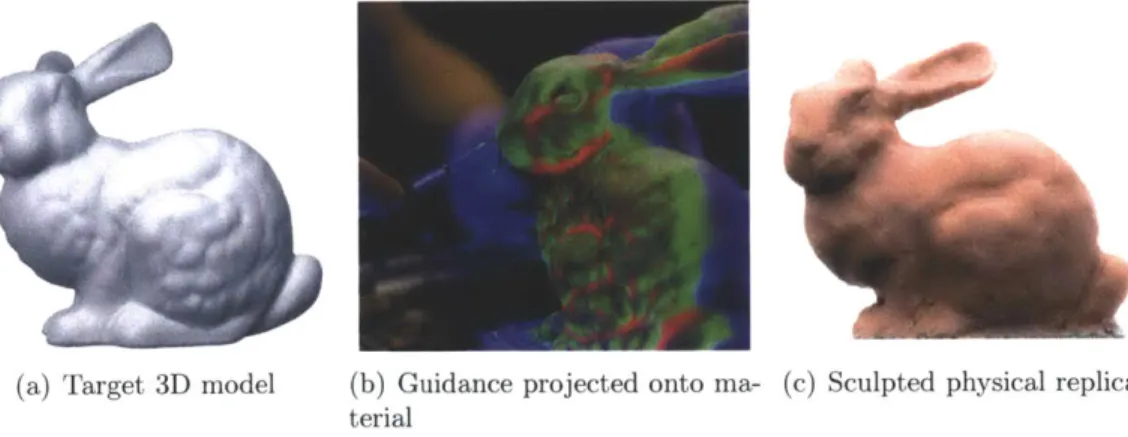
3-1 We assist users in creating physical objects that match digital 3D mod-els. Given a target 3D model (a), we project different forms of guidance onto a work in progress (b) that indicate how it must be deformed to match the target model. As the user follows this guidance, the physical object's shape approaches that of the target (c). With our system, un-skilled users are able to produce accurate physical replicas of complex 3D models. Here, we recreate the Stanford bunny model (courtesy of the Stanford Computer Graphics Laboratory) out of polymer clay. . 29
3-2 Sculpting guidance: A user is given feedback during sculpting by two forms of guidance projected onto the model, which they can toggle between. Guidance is computed by comparing the target depth map (a) to the scanned depth map of the current shape (b). Depth guid-ance (c) illustrates the difference between the two maps and is helpful for matching the position of the surface in absolute 3D coordinates. Edge guidance (d) illustrates the second derivative of the target model (i.e. ridges and valleys), and is useful for recreating fine details once the model is close to the target shape. A smoothly-varying range of colors is used: in depth mode green indicates where the surface should be moved closer to the scanner and red farther, while in edge mode green indicates a positive second derivative (a ridge) and red negative (a valley). In either mode, blue indicates background, so any part of the material colored blue should be removed entirely. . . . . 32
3-3 The head of Michaelangelo's David, in the original marble (photograph by Steve Hanna) (a) and in a 6" tall version made in modeling clay with our system (b) using data from the digital Michelanglo project [45]. The clay model was created by novice sculptors. . . . . 37
3-4 Sculpting from a physical example: With a simple extension, we can use a scan of an existing physical object as a target for sculpting. For example, without any prior cake-decorating experience, we remade this toy car as a cake. We are free to make a replica at a different scale and out of different materials: the car has been scaled-up and made out of madeira cake, frosting, marzipan, cookies, and candy. . . . . . 38
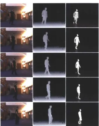
3-5 Stop-motion animation: Our approach can be used to help cre-ate stop-motion animation. We demonstrcre-ate an end-to-end system, in which a 2.5D video (left and center columns) of a real person walking was captured with a Kinect and used to create a claymation sequence
(right colum n). . . . . 39
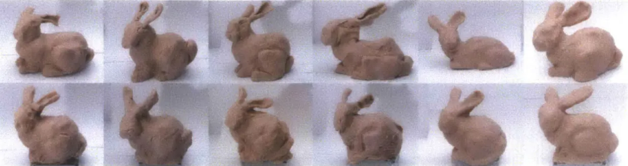
3-6 User testing results: After 10 minutes of training and practice, users were asked to sculpt the Stanford bunny out of polymer clay both freehand (top row), and also using our system (bottom row). 30 minutes were -allotted for each task. The odd columns first used the system and then sculpted freehand, while the even columns sculpted freehand and then used our system. For all users but the artistically-inclined column 3, the system greatly improved their ability to create a correctly-proportioned bunny. . . . . 41
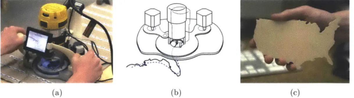
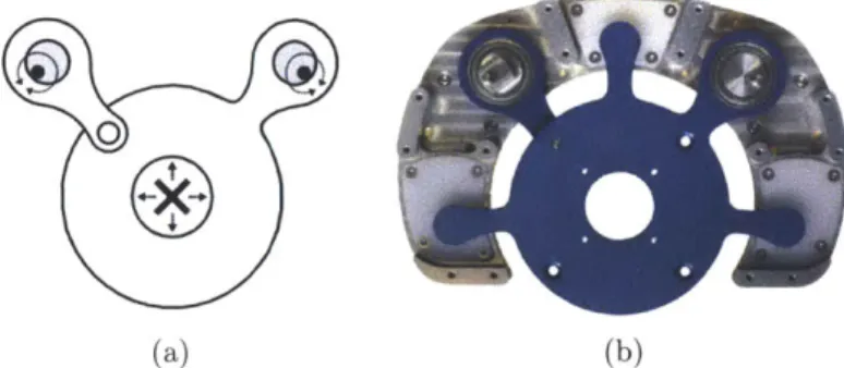
4-1 Overview: (a): A position-correcting tool. The device consists of a frame and a tool (in this case a router) mounted within that frame. The frame is positioned manually by the user. A camera on the frame (top right in the figure) is used to determine the frame's location. The device can adjust the position of the tool within the frame to correct for error in the user's coarse positioning. (b): To follow a complex path, the user need only move the frame in a rough approximation of the path. In this example, the dotted blue line shows the path that the tool would take if its position were not adjusted; the black line is its actual path. (c): An example of a shape cut out of wood using this to o l. . . . . 4 7
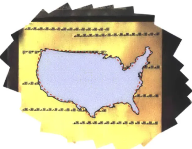
4-2 Map: A scanned map with a plan registered to it. The red dotted line indicates a path that a user could conceivably follow to cut out
the shape. ... ... 50
4-3 Markers: A sequence of markers, with values 1000 to 1006, such as would be printed on a strip of tape. In our current implementation, markers are printed at a size of roughly 0.8" x 0.4". This is small relative to the area of the material the camera can see at once (roughly 8" x 6" ). . . . . 5 1
4-4 Positioning linkage: (a): Our linkage converts the rotary motion of two shafts (filled circles) into translation of a tool (cross) mounted on a sliding stage. This is achieved using eccentrics (shaded circles), which are circular disks rotating about the off-center shafts to produce linear displacement in fitted collars. To properly constrain the degrees of freedom of the stage, one eccentric is directly connected to the stage while the other is connected via an additional hinge. (b): A photo of the actual linkage. . . . . 54
4-5 Freeform motion paths: Each box illustrates a case in which a different path (described below) is used, due to the higher-preference paths being infeasible. In each box, the cross is the current position of the tool, the circle is the range of the positioning system, the green
dot is the target position, and the green path is the selected path. . 56
4-6 User interface: This display shows the shapes of the plan (blue poly-gons); the path that the tool is actually following, which is those shapes offset by the tool's radius (dotted line); the tool's current position (cross); the area cut by the tool (shaded area); and the range of the tool's position correction (black circle). As long as the user keeps the tool path within the correction range, the tool should be able to follow the plan . . . . . 57 4-7 Results: Several shapes cut out from various materials (clockwise
from top left: hardwood, hardwood, paperboard, polycarbonate plas-tic, plywood, and sheet metal). . . . . 59 4-8 Range: A full-size vinyl cutout of a human silhouette (5'6" tall), with
origin al. . . . . 6 1
4-9 Fine details: With a vinyl cutter, the resolution of features is not limited by the width of the bit. Here, we show a 6"-wide sticker with fine details. . . . .. . . . .. . . . . 61 4-10 Accuracy: A scan of a plotted pattern (6" wide) shown with the
design that was used to create it (red). The inset shows an expansion of the area of worst error, with the addition of the line fit to the scan for analysis (green). Note that even here the error is only on the order of the width of the pen. . . . . 63
Chapter 1
Introduction
Digital fabrication devices such as CNC routers and 3D printers have made it possible to fully automatically manufacture objects from a digital plan. They are incredibly precise, and can machine extremely complex shapes as easily as simple ones. However, they remain large and expensive. Much of this cost goes to pay for mechanical components that reproduce physical manipulations, such as large-range positioning, that a human is able to perform as a matter of course. This thesis explores the space of augmented manual fabrication: methods and devices to help a user manually create a physical object. Augmented manual fabrication seeks to take the advantages of a computer's precision and use them to augment, rather than replace, manual fabrication, allowing hybrid methods of creating things that combine the accuracy of an automatic method with the flexibility and availability of manual crafting.
The key advantage of such a hybrid approach is that it leverages, rather than discards, the mechanical ability of a human operator. As a physical device, the human body is extremely capable. Most people find it easy to manipulate tools in complex and finely-controlled ways, over an effectively unlimited working volume. Humans are also excellent at planning physical motions to accomplish a task. However, they cannot sense absolute 3D positions, cannot remember exact 3D shapes, and the precision with which they manipulate objects, while high, is not perfect.
Digital devices, meanwhile, have an almost exactly complementary set of strengths and weaknesses. Even the most advanced and expensive robots have difficulty mov-ing in a non-controlled environment and graspmov-ing and manipulatmov-ing tools and mate-rials, but computers and digital scanners are trivially capable of manipulating large amounts of shape data, accurately scanning a 3D scene, and driving actuators to perform incredibly fine adjustments.
There are therefore multiple fruitful areas for computers to aid humans in manually crafting objects. A computer's ability to manipulate large amounts of shape data can be used to help design the object to be fabricated and plan the fabrication steps. A scanner's ability to accurately perceive a scene can be used to help guide a user during fabrication to make adjustments in exactly the right 3D location. And a digitally-driven actuator can be used to augment or finely adjust the mechanical actuation performed by the user to improve accuracy.
In this thesis, we present two approaches that lie within this space. In the first, sculpting by numbers, we present a method that augments only with guidance, to help a user accurately create a 3D shape that matches a target digital model. In the second, position-correcting tools, we present a method that augments with both guidance and partial actuation, to help a user accurately guide a tool along a 2D path for digital fabrication.
1.1
Sculpting by Numbers
Most people find it challenging to sculpt, carve or manually form a precise shape. We argue that this is not usually because they lack manual dexterity - the average person is able to perform very precise manipulations - but rather because they lack precise 3D information, and cannot figure out what needs to be done to modify a work in progress in order to reach a goal shape. An analogy can be made to the task of reproducing a 2D painting: when given outlines that need only be filled in, as in a child's coloring book or a paint-by-numbers kit, even an unskilled user can
accurately reproduce a complex painting; the challenge lies not in placing paint on the canvas but in knowing where to place it. We therefore present Sculpting by Numbers, a method to provide analogous guidance for the case of creating 3D objects, which assists a user in making an object that precisely matches the shape of a target 3D model.
We employ a spatially-augmented reality approach (see e.g. Raskar et al. [60] or Bimber and Raskar [7] for an overview of spatially-augmented reality), in which visual feedback illustrates the discrepancy between a work in progress and a target 3D shape. This approach was first proposed by Skeels and Rehg [69]. In this approach, a projector-camera pair is used to scan the object being created using structured light. The scanned shape is compared with the target 3D model, and the projector then annotates the object with colors that indicate how the object ought to be changed to match the target. The user follows this guidance to adjust the object and rescans when necessary, bringing the object closer to the target shape over time.
Our proposed method provides guidance that illustrates depth disparities between the current work and the target, similar to the approach of Skeels and Rehg [69], as well as an additional form of guidance, which we call edge guidance, which aids in reproducing high-frequency surface details. We demonstrate an application to reproducing an existing physical object at a different scale or using different materials. We further show how a scene can be repeatedly deformed to match a sequence of target 3D models for the purpose of stop-motion animation. Starting from a depth video recorded with a Kinect, we produce claymation with physically correct dynamics. Finally, we present results of user testing with novice sculptors.
1.2
Position-Correcting Tools
Guiding a user performing manual fabrication can greatly improve accuracy relative to unguided fabrication, but not beyond the user's physical ability to maneuver a tool. For many functional (as opposed to aesthetic) applications, a level of accuracy higher
than can be achieved manually, even with guidance, is often required. Typically, the solution is to handle actuation fully automatically. However, automatic positioning mechanisms, as described above, are cumbersome and expensive, especially for larger-range devices.
We aim to reduce the cost of digital fabrication for the domain of 2D shapes while simultaneously removing constraints on range. Our central idea is to use a hybrid approach to positioning where a human provides range while a tool with a cheap short-range position-adjustment enables precision. Given an input 2D digital plan such as the outline of a shape, the user manually moves a frame containing a tool in a rough approximation of the desired plan. The frame tracks its location and can adjust the position of the tool within the frame over a small range to correct the human's coarse positioning, keeping the tool exactly on the plan. A variety of tools can be positioned in this manner, including but not limited to a router (which spins a sharp bit to cut through wood, plastic, or sheet metal in an omnidirectional manner) to cut shapes, a vinyl cutter to make signs, and a pen to plot designs.
In this approach, the core challenges are localization (determining the current position of the tool) and actuation (correcting the tool's position). For localization, we use computer vision and special markers placed on the material. For actuation, we present a two-axis linkage that can adjust the position of the tool within the frame. We also describe an interface for guiding the user using a screen on the frame, which illustrates the tool's current position relative to the plan. We demonstrate an example of a device, measuring roughly 13" x 10" x 9", that uses our approach and can be fitted with a router or a vinyl cutter, and show results that can be achieved with these tools when they are positioned with our computer-augmented approach.
Chapter 2
Background
Digital augmentation of manual fabrication already occurs in a variety of contexts. Here, we place into context three broad areas in which augmentation can occur: design, in which software tools can help the user create, analyze and fully specify the plan for the object to be fabricated; guidance, in which feedback or instructions presented during the fabrication can help the user execute the plan; and actuation, in which some or all of the actual physical manipulation can be done by a machine.
2.1
Design
Designing an object to be manufactured involves many steps. The appearance and functionality of the object must be conceived, and the mechanical parts that consti-tute the object must be designed. The parts' designs must be made such that they are amenable to the type of manufacturing (e.g. injection molding) that will be used, and often need to be analyzed to determine where stresses and fractures could occur. Finally, the parts must be fully specified with allowable tolerances to enable their manufacture.
In the digital age, much of this process has moved to the computer. CAD modeling programs such as SolidWorks, Pro/Engineer, and CATIA [71, 59, 10] provide
end-to-end systems for designing complex mechanical objects with moving parts. These systems are explicitly geared towards designing objects that will ultimately be man-ufactured (as opposed to used only in a digital context, such as for animation), and as such directly incorporate mechanical engineering tools. For example, a CAD sys-tem will typically include built-in physics simulators, both to predict the gross-scale mechanical motions of the parts, and to perform stress analysis such as with finite-element methods [14].
These tools, as well as more general-purpose 3D modelers, remain difficult and time-consuming to use, due largely to the difficulty of specifying a complex 3D shape. A large variety of approaches have been proposed to make this task easier. On the hardware side,3 i t c [8] and haptic interfaces that make it possible to
"feel" a shape as it is being modeled [25] seek to recreate some of the ease of making a shape with one's hands. On the software side, a large variety of interfaces have been proposed to make 3D modeling more intuitive and natural. Zeleznik et al. [81] proposed a modeling system in which the input was 2D sketches drawn into a 3D view. These sketched shapes were interpreted using techniques from gesture recognition and 3D reconstruction, and enabled the user to perform modeling operations quickly and easily. Igarashi et al. [33] presented a sketch-based system for creating organic 3D models in which modeling operations were even higher-level, and allowed the user to create a 3D shape almost as if sketching a 2D drawing. From these foundational works came a large body of sketch-based modeling approaches for both specifying both mechanical shapes [81, 20, 36, 61, 70] and organic shapes [33, 32, 37, 55, 64, 38, 54].
Recently, much work has focused on developing software methods that integrate fabri-cation considerations directly into the design process. Some of these methods dovetail with specific fabrication technologies such as 3D printers, and seek to ensure success-ful fabrication of objects with desired properties. Bickel et al. [6] propose a method for automatically generating a 3D-printable pattern of multiple materials such that the resulting printed object will match desired deformation characteristics. Alexa et al. [4] demonstrate how to generate 3D-printable relief surfaces that match
user-specified appearances under directed lighting. Hasan et al. [24] and Dong et al. [19] demonstrate systems for fabricating objects with desired subsurface scattering. Stava et al. [72] propose an automatic method for increasing the structural stability of 3D printable objects by analyzing a 3D model to be printed and selectively hollowing, thickening, and adding struts to elements to increase stability.
Other methods seek to design or reformulate existing designs into a format such that they can be fabricated using alternative methods that are less general but have desirable characteristics such as ease or low cost. Two recent works propose methods to generate models of sliding planar slices that approximate target 3D models [28, 51]. Lau et al. [43] propose a method to convert 3D furniture models into fabricatable planar parts.
A recent trend in computer graphics methods for fabrication has been to design interfaces in which fabrication constraints are included in the modeling interface, so that objects designed with the system are guaranteed to have straightforward fabrication. A prototypical example is an interface by Mori and Igarashi [53] for designing stuffed animals. In this task, the stuffed animal has a 3D shape that is determined by a collection of 2D pieces of cloth and the interactions between them and the stuffing. An interface in which the user modeled the 3D shape could easily result in 3D surfaces that were difficult or impossible create out of cloth peices and stuffing, while a modeling system in which the user directly designed the shapes of the cloth pieces would require that the user understand the complex mapping between the 2D cloth shapes and the 3D shape that will result. They therefore propose an interface in which the 2D cloth shapes and the 3D model that will result from these shapes (determined by a rapid physics simulation) are displayed simultaneously, and the user can perform editing operations on either and see the results on the other. In this way the user can easily achieve a desired 3D shape while ensuring that it remains fabricatable in practice.
Other works have proposed interfaces for fabrication-conscious design of other types of objects. Saul et al. [63] proposed a method for designing chairs using a sketch-based
that limits input to shapes that can be easily fabricated out of planar parts. Kilian et al. [40] propose a method for designing shapes that can be produced by folding a single sheet of material. Lau et al. [42] propose an augmented reality interface for designing 3D shapes in which real-world objects can be incorporated as primitives.
2.2
Guidance
Once the object to be manufactured has been fully specified, it must be made. If the construction is being done manually, the builder will need guidance to successfully execute the plan.
The simplest forms of guidance in manufacturing involve simply making the specifica-tion as clear and easy to understand as possible. Tradispecifica-tionally, this was achieved by technical draftsmen creating blueprints, using a long-developed visual language that maximizes the clarity of specification for manufactured parts. More recently, the field of computer visualization has sought to encode visual design principles in algorithms that can automatically generate intuitive static or interactive specifications. Auto-matic visualization techniques have been applied to a wide variety of types of data, ranging from scientific simulation data to medical scans (See Viola et al. [77] for a survey). Visualization specifically of mechanical assemblies and fabrication instruc-tions has also received attention (see e.g. [22, 65]). Agrawala et al. [2] attempted to empirically determine cognitive design principles for designing effective assembly instructions, and then developed an automatic system that implemented those prin-ciples, combining the task of generating the plan with the challenge of visualizing it. This work very directly augments manual fabrication with automatic guidance. Li et al. proposed related approaches to automatically generate interactive cutaway visual-izations of complex shapes [48] and exploded view diagrams of mechanical assemblies
[47].
The visualization of the specification may also take place during fabrication itself. A large body of work has been developed on using augmented reality [5] to provide
guid-ance during the performguid-ance of procedural tasks such as assembly. These typically provide guidance to a user using a head-mounted display that overlays see-through instructions in the context of the user's field of view, an intuitive format that makes it easier to understand the 3D spatial relationships of complex assemblies. In an early, work, Webster et al. [78] proposed using augmented reality for assembly, inspection, and renovation, providing features such as displaying otherwise-invisible information such as the location of rebar in a concrete wall, and guiding the user through com-plex multi-stage assembly processes. Caudell and Mizell [11] proposed applications to wiring layout and composite cloth layup in aircraft manufacture.
Guidance presented to the user during fabrication need not display only information collected in advance such as the plan for the object. Rather, the user can also be guided based on data being collected during fabrication, potentially derived from changing properties of the scene. In a rudimentary form, any mechanical sensor, from a level to a stud-finder, can be thought of as a device for augmenting fabrication using guidance based on data that the user cannot detect unaided. Our augmented reality approach for sculpting uses a more advanced structured light scanner to collect data about the scene that is used to determine guidance that aids the user.
Recent augmented reality systems also display guidance based on the changing prop-erties of the scene itself. A prototypical system in this area is the ARMAR system of Henderson and Feiner [26, 27]. They demonstrate an augmented reality system to aid in the task of the assembly of a motor in the course of maintenance. They track multiple parts of the motor as well as the user's head, and generate a see-through interface on a head-mounted display that describes the current task to be performed (such as aligning two parts or tightening a bolt), shows the location of the salient com-ponents, illustrates the motion required of the user, and provides real-time feedback as the parts are adjusted. By tracking the parts in real time and providing feedback to the user on their positions, the user can be helped to make precise adjustments.
2.2.1
Spatially-Augmented Reality
While many augmented reality devices rely on a head-mounted display to overlay information on the user's view of the scene, another approach for displaying data in context is spatially-augmented reality (see e.g. Raskar et al. [60] or Bimber and Raskar [7]). In SAR approaches, a projector is used to directly annotate the scene itself with an image or interactive interface. These approaches have been used, for example, to turn virtually any flat surface into a monitor by projecting video onto it, or to project an animated face onto a static robot head.
The primary advantage of SAR approaches is that they eliminate the need for the user or users to wear special equipment such as head-mounted displays. However, this approach is also less flexible than head-mounted displays. Virtual objects cannot be created in mid-air, as they can with a head-mounted display, and instead must lie on the surfaces of the physical scene. Furthermore, not all surfaces will work well: certain surfaces such as reflective metals will not show the projected image clearly. Finally, irregular surfaces will cause the projected image to appear warped.
The problem of irregular-shaped surfaces can be largely resolved by scanning the scene using a calibrated camera in conjunction with the projector to perform structured-light scanning. With the resulting information about the shape of the scene, the desired image can be pre-warped such that it appears undistorted when projected onto the known irregular surface.
The augmented sculpting approach presented in this thesis is an example of a spatially-augmented reality method. In this application, the scene must in any case be scanned by a structured-light scanner to determine the feedback that will be shown to the sculptor, so presenting the feedback using the same hardware is economical. Further-more, any surface on which projected images will not be easily visible, such as glossy surfaces, will also be difficult or impossible to scan using structured light, meaning that the necessary information cannot be gathered in the first place and the limitation of the display is a moot issue.
2.3
Actuation
Once the part has been designed, and the user is fully aware of how the design must be executed, the object still must be physically made. Devices to help apply the necessary mechanical actuation are, of course, the oldest form of augmented manual fabrication, as every handheld tool is an example of physical augmentation.
The advent of digital fabrication technologies, such as 3D printers, laser cutters, and
CNC machines, has dramatically expanded the range of ways that a computer can
aid in the mechanical aspects of fabrication. CNC, or computer numerical control, technology simply refers to machine tools that can be controlled directly by a com-puter. This technology was originally applied to milling machines for the purpose of cutting complex shapes out of metal for aircraft parts. Subsequent development has seen numerical control applied to a much wider range of tools for a much wider range of applications. With these devices, it has become possible to fully automatically produce 2D and 3D objects.
Digital fabrication devices can be broadly categorized into subtractive and additive approaches. Subtractive devices start with a block of material larger than the target target shape, and automatically maneuver a tool, such as a router, water-jet cutter, or lathe, to selectively remove material, leaving an object matching the target shape.
By contrast, additive devices, such as 3D printers, build up an object by depositing
(or in some cases selectively hardening) material in precise shapes, typically forming one thin layer at a time and stacking these layers together to form a desired 3D shape. Digital fabrication devices are extremely precise, can be quite fast, and have made it possible to easily manufacture very complex shapes directly from a digital plan. These strengths have made them extremely appealing in certain industrial contexts. They have revolutionized low-volume manufacturing by effectively removing the tool-ing costs (such as creattool-ing a die or mold) that can otherwise dominate production costs for short runs, and further simplify low-volume manufacturing by working di-rectly from a CAD specification. This has made them attractive for tasks such as
rapid prototyping and producing one-off objects such as scientific apparatuses or re-placement parts. They are also used in some high-volume assembly cases where the ability to quickly change the design is essential, such as certain consumer electronics devices. Finally, they are used in some contexts where the ability to machine a shape out of a single block of material, without the artifacts and difficulties imposed by casting, is necessary.
The current designs of CNC devices, however, have drawbacks that have limited wider adoption. CNC devices are typically quite expensive, though recent efforts in the DIY community have made low-priced entry-level tools available [30, 39, 49, 21, 66]. They also typically must surround the material being worked on, meaning that a given device can only produce objects smaller than itself, limiting the working volume. They also suffer from fabrication artifacts, such as "stepping" artifacts in objects generated by 3D printers that reveal the different layers out of which the object was made. Finally, they are limited in the range of materials they can work with, especially for additive devices, and multi-material fabrication is particularly challenging. A wide range of additional applications could become viable were these restrictions to be eliminated. Most immediately, there is a large class of potential consumers of digital fabrication technologies that cannot afford the cost or space requirements of a digital fabrication device. These include small-scale industries but also individual consumers. A large amount of enthusiasm for CNC devices has recently been gener-ated by the DIY
/
"maker" communities, who see uses for CNC technology in home improvement, art, and personalized consumer goods. Current industrial consumers of CNC technologies could also see additional applications and improved utility if cost and/
or space requirements were reduced. CNC devices are also typically not portable, meaning the job must be brought to the machine; were it possible to do the reverse, applications such as in-situ repair or renovation would become possible. Many of the drawbacks of CNC devices arise from the nature of the mechanical sys-tems used to position the tool. The most typical system is a computer-controlled 3-axis stage or gantry. As described, such a system can only move a tool within itsown volume, meaning that to work on a large object, a large device is required, which imposes space requirements. Furthermore, as the stage gets larger, it becomes increas-ingly difficult (and consequently expensive) to maintain accurate positioning over the entire range. As an illustration, a 2' x 1.5' ShopBot CNC mill costs approximately
$6,000, while a 5' x 8' ShopBot mill costs over $20,000 [68].
This thesis presents an alternative, hybrid method for tool positioning for digital fabrication, in which the user provides large-scale, low-accuracy positioning of a tool, and the tool is digitally actuated over only a small range to correct that positioning. This type of hybrid approach to actuation is comparatively less common, but aims to address the limitations of both manual crafting and current digital fabrication technologies by combining elements of each in a hybrid approach.
2.4
Hybrid methods in surgical applications
Hybrid manual-automatic methods have been particularly well developed in their applications to surgery. A variety of systems have been developed that range from providing only guidance and sensing to partially or fully automating the mechanical act of surgery.
Methods that provide only guidance typically involve registering and integrating sets of scans of a patient, registering these scans onto the patient during surgery, and presenting the scanned data to the surgeon during the operation. Each of these represents a research field in its own right, and requires a combination of techniques, including advanced image registration methods to integrate data from completely different sensor modalities; 3D scanning technology to detect the shape of the patient's skin during surgery to provide a reference onto which data can be registered; and augmented-reality methods that display the information to the surgeon in an intuitive manner, such as on a head-mounted display. An overview of the field in general can
Of closer relevance to the task of digitally-augmented manual fabrication are the variety of robotic methods that have been developed for assisting the surgeon with the mechanical task of performing the surgery itself. The conceptually simplest form of robot-assisted surgery is telesurgery, which was an outgrowth of tele-control for robots such as in the space program [29]. In this approach, the surgeon uses a remote console to control a robot (typically consisting of one or more robotic arms) to perform the surgery. One clear advantage of this is that the surgeon need not be colocated with the patient, though in practice this application has been dogged by latency issues. Other key advantages are that the motions of the surgeon can be recreated at a smaller scale, e.g. for microsurgery [41], or the robotic arms performing the surgery may be smaller than a surgeon's hands, allowing for smaller incisions to be made into the patient [35].
On the other end of the scale of automation is supervisory-controlled systems, in which the robot performs the surgery autonomously (though with human supervi-sion). In these applications, a surgeon carefully plans the motions to be performed in advance, but the actual implementation is entirely automatic. This type of approach is particularly suited to applications where the surgery to be performed is straight-forward conceptually but difficult mechanically. For example, a robot may be used to cut away a precise half sphere into a bone to make a site for a mechanical joint to be placed.
Finally, there exist approaches in which the tool is controlled by both the humand and a robot, called shared-control robotic surgery systems. Such a system typically in-volves motions being planned and executed by a human, but modulated by a machine. For example, in the case of a surgery performed near critical tissues, the surgeon may mark certain regions of the 3D working volume as forbidden; then, when manipu-lating a tool, a robotic component will prevent the tool from entering those regions [50]. Or, the robot may act to smooth out the motions of the surgeon, to eliminate tremors [74].
collabora-tion in physical tasks. Researchers developing these methods have thought carefully about the relative abilities of humans versus machines in planning, sensing, and me-chanical actuation, and drawn conclusions as to what challenges are most amenable to hybrid solutions [31]. Interestingly, these methods have focused almost entirely on combining human judgment with robotic manipulation. By comparison, in this the-sis, we propose methods in which the human operator is used largely as a mechanical actuator, and the automatic component performs the sensing and motion planning.
Chapter 3
Sculpting by numbers
3.1
Introduction
In this chapter, we present a method for augmenting manual fabrication by sculpting in which the only augmentation is in the form of guidance projected onto the object. We use a projector/camera pair to scan a work in progress, and use that to project
(a) Target 3D model (b) Guidance projected onto ma- (c) Sculpted physical replica terial
Figure 3-1: We assist users in creating physical objects that match digital 3D models.
Given a target 3D model (a), we project different forms of guidance onto a work in progress (b) that indicate how it must be deformed to match the target model. As the user follows this guidance, the physical object's shape approaches that of the target
(c). With our system, unskilled users are able to produce accurate physical replicas of complex 3D models. Here, we recreate the Stanford bunny model (courtesy of the Stanford Computer Graphics Laboratory) out of polymer clay.
guidance onto the object itself that indicates how the surface needs to change in order to make the shape match a target 3D model. Thus, in this case, the computer makes up for a person's inability to accurately detect absolute 3D positions, but leaves all physical manipulation to the user. When provided with just this missing ability, even an unskilled user is able create an accurate physical replica of a digital 3D model.
3.2
Related work
As described in Section 2, recent work in computer graphics has focused on software techniques that enable alternative methods for fabrication, and our technique falls
into this category.
Our approach shares some similarities with previous hybrid manual-automatic meth-ods that have been used for 2D design, again to provide automatic guidance to a user who is performing the task. Painters have used photographs or a camera obscura as references [13, 57]. Dixon et al. [18] proposed a hybrid method for the task of sketching a human face from a reference photograph in which the user is guided by automatic feedback. The guidance included high-level sketching principles for each part of the face as well as specific feedback on how to adjust the freehand drawings to more closely match the shape of the reference image. ShadowDraw [44] proposed a more open-ended system in which a user is allowed to draw freely while a "shadow image" of suggestive contours is updated and displayed behind the sketch to illustrate possible sketch completions.
Our approach to guided sculpting involves scanning the work in progress and pro-jecting guidance that annotates the physical object. 3D scanning has been an active area of research for many years, with a variety of optical methods being proposed; see Chen et al. [12] for a survey. One of the oldest and most robust methods involves projecting a sequence of Gray codes and imaging the result to retrieve depth infor-mation [34, 9, 62]. This method is simple to implement, robust, and able to capture a full depth field quickly.
3.3
System design
The core operation in guided sculpting is creating a physical object that matches a target 3D model. This is done by projecting different forms of guidance onto the object that illustrate how it must be changed to match a target shape. All adjustments to the model are done manually, which naturally supports a wide range of materials and shapes. The guidance makes it possible to achieve complex and precise shapes. This approach requires two main technical components: a method for scanning a 3D shape at high spatial and depth resolution, and a projector registered to the same coordinate system to project guidance onto the material. We achieve both goals with the same hardware by using a projector-camera pair to perform structured light scanning with Gray codes (e.g. [9]). While faster scanning methods exist, e.g. the Primesense/Microsoft Kinect, they typically have much lower spatial resolution, which is more of an issue to us than refresh rate. We require the user to explicitly request each new scan, which has two advantages: the guidance does not change unexpectedly, and the user's hands are not scanned and confused with the target object.
3.3.1
Scanning
The input to the scanning process is a target 3D model, which may be a mesh or a point cloud. It is virtually positioned within the working volume, and a block of raw material (e.g. clay) is placed at roughly the same real position.
Whenever the user initiates a scan, we project a sequence of Gray codes onto the scene and photograph the scene illuminated by each code. These images give us a corre-spondence from camera coordinates to projector coordinates. We filter out invalid or implausible correspondences, and then invert this map to compute a correspondence from projector coordinates to camera coordinates. From this we triangulate to com-pute a depth map from the projector's perspective. We also comcom-pute a depth map of
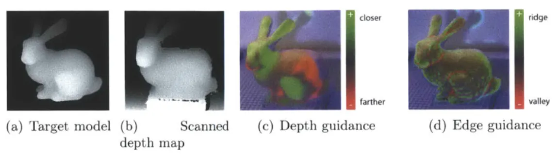
closer ridge
farther valley
(a) Target model (b) Scanned (c) Depth guidance (d) Edge guidance depth map
Figure 3-2: Sculpting guidance: A user is given feedback during sculpting by two
forms of guidance projected onto the model, which they can toggle between. Guidance is computed by comparing the target depth map (a) to the scanned depth map of the current shape (b). Depth guidance (c) illustrates the difference between the two maps and is helpful for matching the position of the surface in absolute 3D coordinates. Edge guidance (d) illustrates the second derivative of the target model (i.e. ridges and valleys), and is useful for recreating fine details once the model is close to the target shape. A smoothly-varying range of colors is used: in depth mode green indicates where the surface should be moved closer to the scanner and red farther, while in edge mode green indicates a positive second derivative (a ridge) and red negative (a valley). In either mode, blue indicates background, so any part of the material colored blue should be removed entirely.
the target model rendered from the same perspective. Finally, we compare the depth maps to compute the guidance that we project onto the object. We describe each of these operations in detail below.
Obtaining pixel correspondences Gray-code-based structured light scanning op-erates by projecting a sequence of black and white horizontal and vertical bars onto a scene and recording the resulting images. By examining the illumination of a single camera pixel across all projected patterns, one can determine the X and Y coordinate of the projector pixel that was imaged by that camera pixel.
While the basic approach is straightforward, a number of factors can create incorrect correspondences. First, some camera pixels may image parts of the scene that are not illuminated by the projector at all. These can be detected and excluded by ignoring pixels that do not vary substantially between images in which the projector displays entirely white and entirely black.
reflections of light cast by the projector. These camera pixels will vary appropriately between white and black projector images, and a corresponding projector pixel can be computed for them; however, this invalid correspondence will corrupt the depth map at that projector pixel. We are able to reject the majority of these correspondences with a consistency check. Given the homographies for the camera and projector, we can determine the world-space ray that corresponds to each camera and projector pixel. These rays ought to intersect within the working volume in the case of a true correspondence. If the rays do not approximately intersect, as may be the case if the camera is seeing a reflection, we reject the correspondence. Put another way, the scan in X, the scan in Y, and the epipolar constraint combine to overconstrain the pixel correspondence, which lets us reject invalid pixels. This constraint also helps eliminate spurious correspondences detected due to noise.
A final source of inaccuracy can arise when narrow alternating black and white columns in a fine-scale Gray code pattern are blurred into an average gray due to the combination of camera and projector defocus. In our case, the working volume is often close to the camera and projector, so their depths of field are relatively shallow. Loss of the finest Gray code patterns results in losing the least-significant bits of the projector-camera correspondence.
When coarsely shaping an object this loss of resolution does not matter, but towards the end of the sculpting process it becomes important. We therefore allow the user to perform a slightly more time-consuming "precise" scan inspired by laser plane sweep scanning (e.g. [15]). In a simple implementation, we could project a single white row or column that sweeps across the entire projector image, and for every camera pixel simply record for which code the illumination was highest. This method is robust to defocus, but slow. We instead project the Gray code patterns as usual to compute a correspondence that may be incorrect in the least significant bits. We then sweep one-pixel-wide vertical or horizontal lines that recur every 8 rows or columns across all 8 positions, and record the position of maximum illumination for every camera pixel to correct the three least-significant bits of the correspondence. This precise
scan takes about 7 seconds, and gives us a depth resolution of under 1mm at the center of the working volume.
Computing depth maps As we will be displaying guidance using the projector,
we need to compute the depth map from the projector's point of view rather than the camera's. To achieve this, we must resample the correspondence into the projector's point of view.
We do so by splatting: each valid camera pixel contributes to a 7 x 7 kernel with exponential falloff about the corresponding projector pixel. The contributions are summed in homogeneous coordinates and then normalized to produce a camera co-ordinate for some subset of projector pixels. The kernel size chosen i enough to interpolate across small holes in the depth map, which arise from projector pixels not seen by any camera pixel.
Given these resampled correspondences and the homographies for both camera and projector, we can triangulate to compute depth values for each projector pixel. Mean-while, the depth map for the target model is computed by rendering it from the pro-jector's point of view using the propro-jector's calibrated homography as the OpenGL projection matrix. These depth maps are then compared to compute the guidance that we project onto the material.
Hardware setup We use a 3M MP160 projector running at 800 x600 at 60Hz and a
Nokia N9 camera-phone using the FCam API [1] generating raw data at 1632 x 1232 at 13Hz (75ms exposure time). The FCam API makes it easier for us to synchronize the camera with the projector, and the raw stream prevents us from losing resolution to demosaicing. Gray codes do not rely on color or spatial coherence, so we can treat each pixel independently and ignore the Bayer mosaic. The separation between camera and projector is 5", and they placed roughly 2' from the center of the work area. We compute world-space homographies for the camera and projector by scanning a known planar calibration target placed at two known depths in the work volume.
3.3.2
Guidance
We provide two forms of guidance, which the user may toggle between depending on the context. Each form is useful for recreating a different aspect of the model's
appearance.
Depth guidance is used to achieve the correct surface position in absolute 3D space. In the this mode, projector pixels are colored based on the difference between the scanned depth at that pixel and the target depth (Figure 3-2 (c)). Green indicates areas where the user must bring the surface closer to the projector and red indicates areas where the user must move the surface farther away. Pixels that do not intersect the target model are colored blue. The range of the scale is user-tunable. The user can also probe the exact depth error in millimeters at a particular point by mousing over that pixel on the laptop controlling the projector.
Edge guidance depends only on the target 3D model, and is used to help the user match the high-frequency surface details of the target 3D model. In this mode, projector pixels are colored according to the second derivative of the target depth map (i.e. ridges and valleys, as shown in Figure 3-2 (d)). This color follows the same scale as the depth feedback mode, and its range can be similarly tuned.
Rotation. The method described so far assists a user in achieving the correct shape from a single point of view. However, a complete model must be correct from all sides. The challenge is to rotate the target model and the partial sculpture by the same amount about the same axis of rotation so the user can continue without invalidating work already done. While automatic methods (e.g. ICP [82]) could be employed to deal with this, we handle this more simply by sculpting atop a Lego stage, which can be accurately rotated by 90 degrees around a known axis.
3.4
Applications
Using our system in practice involves an interplay of computer guidance and human intuition, in which both the precision of the computer and the intuition of the artist are required to create an object with the correct proportions and aesthetic qualities. In this process, the computer's ability to accurately detect absolute 3D shape in world coordinates means that the guidance can be relied upon to achieve the correct rela-tive positions and sizes of features of the model, which can otherwise be extremely challenging for a novice sculptor. However, the process also relies on the user's un-derstanding of the shape. One simple reason is that the guidance must be interpreted and internalized, as it will both be blocked by the user's hands and tools, and is slowly invalidated as the user works on the model between scans. As users become familiar with the system, they quickly become able to perceive how a shape must be deformed and judge when to initiate a rescan.
A less obvious but important way in which we benefit from having an artist (even if a novice one) "in the loop" is that the user can make unprompted changes to the model to achieve a desired aesthetic appearance. Thus, a user may interpret the projected guidance liberally, and perform freehand adjustments to recreate salient details. This can both speed the creation of major features and enable the reproduction of fine-detail surface features that are too small to be individually highlighted and reproduced using the system.
We describe how this process plays out for the basic case of making a shape that matches a target 3D model, and go on to explore additional applications.
3.4.1
Creating an object that matches a 3D model
We found that use of our system fell into a fairly consistent pattern. A typical modeling session will begin in depth guidance mode. Using this the user will establish the coarse shape and silhouette of the model. As the model approaches the target
(a) (b)
Figure 3-3: The head of Michaelangelo's David, in the original marble (photograph
by Steve Hanna) (a) and in a 6" tall version made in modeling clay with our system
(b) using data from the digital Michelanglo project [45]. The clay model was created
by novice sculptors.
shape, the user will make successively smaller adjustments to the object, shortening the red-to-green guidance range as necessary to highlight the necessary adjustments. Eventually, the user will have a shape that matches the target 3D model in absolute coordinates to the limit of the user's ability to model and the system's ability to scan.
Even after the model has been made to match the target 3D shape as closely as possible in depth guidance mode, the surface may still lack high-frequency surface details, such as wrinkles or the rough surface of hair. These details are often essential to the aesthetic appearance of a model, but are difficult to replicate with simple depth feedback: they may be finer than the scan can resolve, or may be hidden by low-frequency depth discrepancies that, although larger, can be ignored. Therefore, users will typically finish a model by switching to edge guidance mode. In this mode, they can see the locations of ridges, valleys, and other high-frequency details projected onto the surface, and use those as a starting point for an artistic pass on the surface.
The user will usually want to shape an object from all sides. Rather than forming the model perfectly from one side and then rotating, it is generally easier to form the material to match the target model roughly from all sides first, and then make successively higher-detail passes from each direction. This minimizes the problem of alterations to one side affecting already-completed regions of another.
Figure 3-4: Sculpting from a physical example: With a simple extension, we
can use a scan of an existing physical object as a target for sculpting. For example, without any prior cake-decorating experience, we remade this toy car as a cake. We are free to make a replica at a different scale and out of different materials: the car has been scaled-up and made out of madeira cake, frosting, marzipan, cookies, and
candy.
found that our system enabled unskilled sculptors to achieve far better results than they would otherwise be capable of, while giving them a sense of ownership of the resulting creations that would be absent with an automatically-produced object.
One unexpected possibility allowed by our approach is collaborative sculpting. Be-cause the computer guidance provides a common goal to work towards, it is possible for multiple users to work on a sculpture at the same time. This is both time-saving
and highly enjoyable.
3.4.2
Sculpting from a physical example
Our approach can also be used with a simple extension to allow the user to create an object not just from a digital 3D mesh, but also from an already-existing physical object. To do this, the user places an object in front of the projector-camera pair and scans it using the method above, rotating it and scanning it from all four directions. The recovered point clouds are saved. The model is then removed and the stored point clouds are used as the target shape for modeling as above.
Because we use the point cloud recovered by the scanning algorithm directly, we are able to sidestep the difficulties and edge cases of attempting to reconstruct a full 3D
Figure 3-5: Stop-motion animation: Our approach can be used to help create
stop-motion animation. We demonstrate an end-to-end system, in which a 2.5D video (left and center columns) of a real person walking was captured with a Kinect and used to create a claymation sequence (right column).
mesh from a scan. In addition, we allow the user to change the scale or the materials of the reproduction relative to the original.
To illustrate the flexibility of this process, we scanned a toy car and used our system to recreate it at a scaling factor of 2.5 x as a cake consisting of a mixture of edible materials (Figure 3-4). A timelapse of the process can be seen in the video that accompanies this paper. The completed cake was eaten and enjoyed.
3.4.3
Stop-motion animation
Our approach also adapts well to being used as a guide for stop-motion animation. By loading a series of targets, instead of just one, and allowing the user to flip between these targets, it becomes possible to generate a series of snapshots of a physical object
![Figure 3-3: The head of Michaelangelo's David, in the original marble (photograph by Steve Hanna) (a) and in a 6" tall version made in modeling clay with our system (b) using data from the digital Michelanglo project [45]](https://thumb-eu.123doks.com/thumbv2/123doknet/14126203.468385/37.918.289.617.139.325/figure-michaelangelo-original-photograph-version-modeling-digital-michelanglo.webp)