DOE/ET-51013-291
Axisymmetric Control in Tokamaks
David A. Humphreys Plasma Fusion Center
Massachusetts Institute of Technology Cambridge, MA 02139
February 1991
This work was supported by the U. S. Department of Energy Contract No.
DE-AC02-78ET51013. Reproduction, translation, publication, use and disposal, in whole or in part by or for the United States government is permitted.
AXISYMMETRIC CONTROL IN TOKAMAKS
by
DAVID ALLAN HUMPHREYS
S.B., Electrical Engineering
Massachusetts Institute of Technology (1982) and
S.B., Physics
Massachusetts Institute of Technology (1982)
Submitted to the Department of Physics
in partial fulfillment of the requirements for the degree of
DOCTOR OF PHILOSOPHY
at the
MASSACHUSETTS INSTITUTE OF TECHNOLOGY
February 1991
@
Massachusetts Institute of Technology 1991Signature of Author... Department of Physics February 25, 1991 Certified by ... Ian H. Hutchinson Thesis Supervisor A ccepted by ...
AXISYMMETRIC CONTROL IN TOKAMAKS
by
DAVID ALLAN HUMPHREYS
Submitted to the Department of Physics on February 25, 1991, in partial fulfillment of the requirements for the degree of Doctor of Philosophy
in Physics
ABSTRACT
Vertically elongated tokamak plasmas are intrinsically susceptible to vertical ax-isymmetric instabilities as a result of the quadrupole field which must be applied to produce the elongation. The present work analyzes the axisymmetric control necessary to stabilize elongated equilibria, with special application to the Alcator
C-MOD tokamak. A rigid current-conserving filamentary plasma model is applied
to Alcator C-MOD stability analysis, and limitations of the model are addressed.
A more physically accurate nonrigid plasma model is developed using a perturbed
equilibrium approach to estimate linearized plasma response to conductor current variations. This model includes novel flux conservation and vacuum vessel stabiliza-tion effects. It is found that the nonrigid model predicts significantly higher growth rates than predicted by the rigid model applied to the same equilibria.
The nonrigid model is then applied to active control system design. Multi-variable pole placement techniques are used to determine performance optimized control laws. Formalisms are developed for implementing and improving nominal feedback laws using the C-MOD digital-analog hybrid control system architecture.
A proportional-derivative output observer which does not require solution of the
nonlinear Ricatti equation is developed to help accomplish this implementation. The nonrigid flux conserving perturbed equilibrium plasma model indicates that equilibria with separatrix elongation of at least K8,
=
1.85 can be stabilizedrobustly with the present control architecture and conductor/sensor configuration. Thesis Supervisor: Ian H. Hutchinson
Acknowledgments
I would like to thank the many people who have made my graduate years at MIT
so rewarding and enjoyable. While graduate school is fraught with many trials, the people with whom we work can transform these trials into positive experiences. In this regard I have been very fortunate. My supervisor, Prof. Ian Hutchinson, has always been generous with both his time and his support. It has been a true privilege to be able to work with him during my time at Alcator, and I will always be grateful for that opportunity. He is the finest teacher I have ever known.
I would also like to thank my thesis readers, Prof. Jeffrey Freidberg and Prof.
Miklos Porkolab, for their encouragement and helpful suggestions. Special thanks are also due Dr. Steven Home and Dr. George Johnston, for their generous sharing of wisdom and spirit.
I am also grateful to my fellow graduate students and friends at the Plasma Fusion Center who have helped me in one way or another to survive the ordeals and remain human throughout. In particular, I would like to extend my appreciation to Scott Haney, Warren Krueger, Frank Wong, Pat Stewart, Tom Luke, Paul Stek, Gerry Tinios, and Chi-Wa Tsui.
Finally, I would like to thank my family for their love and support throughout the long years. To my brother, Steve, now as always, gratitude beyond words. To my parents, past and present, I dedicate whatever good may come of my work. My thanks will never be enough, yet will always be beyond measure. To my sister, Heather, my thanks for open arms and open heart.
Most importantly of all, my deepest gratitude goes to Sharon, Jessica, and Jared, who have perservered throughout, and have always provided the color, the flavor, and the music to make life ever more beautiful each day.
Contents
Abstract
Acknowledgments
Table of Contents
List of Figures
List of Tables
1 Introduction1.1 Rigid Filament-Circuit Model ... 1.2 Perturbed Equilibrium Model ...
1.3 The Alcator C-MOD Tokamak ...
1.4 Axisymmetric Control in Tokamaks ...
2 Tokamak Physics
2.1 Basic Description and Terms ...
2 3 4 10
17
19 21 25 27 28 30 312.2 Tokamak Equilibrium . . . .i . . .
2.2.1 Ideal Magnetohydrodynamics . . . .
2.2.2 Equilibrium . . . .
2.2.3 The Grad-Shafranov Equation . . . . 2.2.4 Shaped Plasmas . . . .
2.3 Tokamak Stability . . . ... . . . . 2.3.1 Kink Modes . . . . 2.3.2 MHD Growth Rates . . . .
2.4 The Vertical Instability . . . .
2.4.1 Physical Origin: Decay Index . . . .
2.4.2 Conductor Effects . . . .
2.5 Remarks . . . .
3 Rigid Plasma Modeling for Vertical Stability
3.1 Rigid Filament Plasma Model . . . . 3.2 Analysis of Simplifying Approaches . . . . 3.2.1 Massless Approximation . . . .
3.2.2 Plasma Filaments . . . .
3.3 Marginal Wall Position Studies . . . .
3.4 Alcator C-MOD Vertical Stability Analysis Us
3.4.1 Machine Description and
3.5 Passive Results . . . .. 3.5.1 C-MOD Equilibria . . .
General Discu
Analysis
ing the Rigid Model
ssion . . . . 35 35 37 39 41 42 43 44 45 45 47 48 51 52 55 55 57 68 74 74 83 83
3.5.2 Vacuum Vessel Studies . . . . 86
3.5.3 Stabilizing EF Coils . . . . 89
3.6 Remarks . . . . 90
4 Perturbational Equilibrium Plasma Response Model 93 4.1 Modeling Plasma Response with Perturbed Equilibria . . . . 94
4.1.1 Quasi-equilibrium Assumption . . . . 94
4.1.2 Alternative Approaches . . . . 96
4.2 Current-Conserving Algorithm . . . . 98
4.3 Vacuum Vessel Effects . . . 101
4.4 Flux Conservation . . . . 104
4.5 Computational Tools and Accuracy . . . 109
4.6 Passive Analysis . . . . 110
4.7 Testing of the Model . . . 123
4.7.1 Passive Growth Rate Convergence Studies . . . . 123
4.7.2 EF Coil to Vessel Current Mapping . . . . 127
4.7.3 Comparison with TSC . . . . . . 138
4.8 Discussion . . . 141
5 Stability Control Analysis 144 5.1 General Characteristics of Vertical Active Control . . . 145
5.2 Simple Analytic Limits to Controllability . . . 146
5.3 Rigid Model with Displacement Feedback . . . 149
5.5 5.6
5.4.1 State Space Equations and Terminology . . . . 156
5.4.2 Tokamak Axisymmetric Control Problem . . . . 158
Modeling Power Supply Dynamics . . . . 160
Discussion . . . 162
6 Design of Tokamak Equilibrium Control Systems 166 6.1 Pole Placement ... . 167
6.1.1 Full State Feedback ... 168
6.1.2 Full State Algorithm . . . 169
6.1.3 Output Feedback . . . 172
6.1.4 Output Observers . . . .. . . 173
6.2 Applications of Pole Placement . . . 179
6.3 Alcator C-MOD Control Architecture . . . 180
6.3.1 The Hybrid Control System . . . 181
6.3.2 Modeling PD Results with the Hybrid . . . 186
6.3.3 Direct SVD Implementation . . . . 187
6.3.4 Implementing General State Interpreters . . . 188
6.3.5 Shape Predictor A,,. =A, . . . . 189
6.3.6 Principal Vector A,,,w =.A . . . . .. 190
6.3.7 Toroidal Multipole A,,,.d = A . . . . .. . 191
6.3.8 Passive Eigenvector A,. =.. A, . . . . 192
6.3.9 Application of State Interpreters and Hybrid Observer . . . 193
6.4 Time Domain Performance ... 199
6.4.1 Step Response of Second Order System . . . . 200
6.4.2 Time Domain Design . . . . 203
6.5 Frequency Domain Performance . . . . 208
6.5.1 Single Variable Bode Plots . . . . 208
6.5.2 Multivariable Bode Plots . . . . 210
6.6 Error Robustness . . . . 216
6.6.1 Model Error Robustness . . . . 216
6.6.2 Signal Error Robustness . . . . 218
6.7 The Design Process . . . . 219
6.7.1 Performance Criteria . . . . 220
6.7.2 Design Iteration and Refinement . . . . 222
6.8 Control Design for Example Equilibrium . . . . 223
6.9 Discussion . . . . 240
7 Summary and Conclusions 243 7.1 Rigid Plasma Models . . . . 244
7.2 Perturbed Equilibrium Plasma Model . . . . 245
7.3 Active Control Analysis . . . . 246
7.4 Axisymmetric Control Design . . . 247
7.5 Conclusions . . . . 249
List of Figures
2.1 Basic tokamak geometry. . . . . 34
2.2 Quadrupole field addition for plasma elongation. . . . . 36 2.3 Definition of elongation, r. b/a. . . . . 50 3.1 Growth rates normalized to the characteristic Alfv6n frequency (X
al/v, where s is the actual growth rate), as a function of the stabi-lization factor, 7 a
/
. . . 62 3.2 Flux due to actual plasma current distribution for equilibrium ex. 63 3.3 Flux due to a single filament modeling equilibrium exi, located atthe exi current centroid. . . . 64
3.4 Growth rates for single filament plasma as a function of filament ra-dial position on the midplane (eq6). RO denotes the current centroid, at R = 0.65m, while the magnetic axis is located at R = 0.665m. . . 65
3.5 Growth rates for single filament plasma as a function of filament
ra-dial position on the midplane (eq7). R. denotes the current centroid, at R = 0.65m, while the magnetic axis is located at R = 0.665m. . . 66
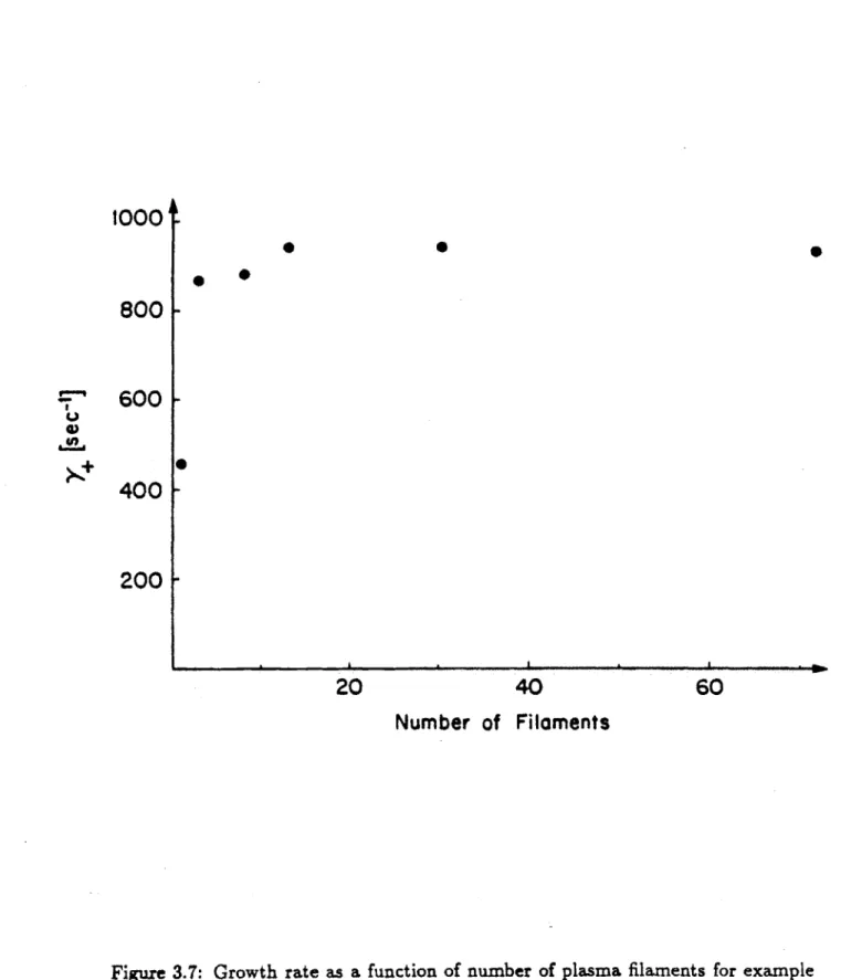
3.6 Growth rate as a function of number of plasma filaments for example
3.7 Growth rate as a function of number of plasma filaments for example
r = 2.0, 6 = .32 equilibrium. . . . 69 3.8 Growth rates as a function of wall distance, illustrating the critical
distance for onset of ideal instability for a conformal D-shaped wall and a multifilament rigid plasma model. . . . 72
3.9 Growth rates as a function of wall distance, illustrating the critical
distance for onset of ideal instability for a C-MOD vacuum vessel model and a multifilament rigid plasma model. . . . 73
3.10 Growth rates as a function of wall distance, illustrating the critical
distance for onset of ideal instability for a conformal D-shaped wall and a single filament rigid plasma model. . . . 75
3.11 Alcator C-MOD machine geometry. Arrows indicate EF coils and
the OH stack. EFC denotes the vertical control coil pair. Note the "notched" OH coil design, consisting of the single large OH1 segment and two independently driven OH2 coils. . . . 78
3.12 Discretized conductor model of the Alcator C-MOD machine
geom-etry. Solid squares denote vacuum vessel elements, and EF coils are represented by open squares marked with "X". Diamonds denote flux loops, and triangles, B, coils. Current contours of a typical equilib-rium are shown. . . . 79
3.13 Current distribution for the dominant asymmetric pure vacuum
ves-sel mode; the plasma and EF coils are absent. . . . .. 80
3.14 Current distribution for the dominant symmetric pure vacuum vessel mode; the plasma and EF coils are absent. . . . 81
3.15 Current distribution for the dominant asymmetric mode with vacuum
3.16 Current distribution for the dominant symmetric mode with vacuum
vessel and EFCU/L included; the plasma is absent. . . . 84
3.17 Original rectangular "picture-frame" vacuum vessel configuration. . 88 3.18 Discretized model of rectangular "picture-frame" vacuum vessel. . . 91
3.19 Example of discretization of "Original Design Set" equilibria. Shown here is equilibrium eq7, a single null, n = 2, S., = .32 case. . . . 92
4.1 Illustration of approximate edge flux conservation. . . . . 114
4.2 Poloidal flux contours for base equilibrium eq8. . . . . 115
4.3 Poloidal flux contours for base equilibrium eq9. . . . . 116
4.4 Poloidal flux contours for base equilibrium eq10. . . . . 117
4.5 Unstable vertical mode conductor current distribution for equilibrium eq8 with vacuum vessel + EFCU/L(antiseries) stabilization. See text for symbol interpretation. . . . 118
4.6 Unstable vertical mode vacuum flux distribution for equilibrium eq8 with vacuum vessel + EFCU/L(antiseries) stabilization. See text for symbol interpretation. . . . 119
4.7 Unstable vertical mode conductor current distribution for equilibrium eq9 with vacuum vessel + EFCU/L(antiseries) stabilization. See text for symbol interpretation. . . . 120
4.8 Unstable vertical mode vacuum flux distribution for equilibrium eq9 with vacuum vessel + EFCU/L(antiseries) stabilization. See text for symbol interpretation . . . .. . . . 121
4.9 Unstable vertical mode conductor current distribution for equilibrium eq10 with vacuum vessel + EFCU/L(antiseries) stabilization. See text for symbol interpretation. . . . 122
4.10 Unstable vertical mode vacuum flux distribution for equilibrium eq1O with vacuum vessel + EFCU/L(antiseries) stabilization. See text for symbol interpretation. . . . 125
4.11 Decay index as a function of AZ - Z - Z,. along the line R = R..
The decay index becomes increasingly destabilizing as JAZI increases. 126
4.12 Decay index as a function of AZ = Z - Z. along the line R =
R,., + 5cm. The decay index becomes increasingly destabilizing as
IAZI
increases. . . . .. . . 131 4.13 The singular values of %P,, for equilibrium eq9. . . . . 1324.14 Plasma surface flux mapping locus, E, for equilibrium eq9. Dark regions surrounding the current contours represent the mapping locus. 133
4.15 Vacuum vessel current derived fluxes at the mapping locus 6 vs. flux due to "equivalent" EF coil currents for the passive unstable mode of equilibrium eq9 (stabilized by vessel only). . . . 134
4.16 Vacuum vessel current derived fluxes at the mapping locus E vs. flux due to "equivalent" EF coil currents for a random distribution of vessel currents. . . . 135
4.17 A random distribution of vessel currents used as an example for assessment of the accuracy of the mapping from vessel currents to
"equivalent" EF coil currents. . . . 136
4.18 Vacuum vessel current derived fluxes at the mapping locus E vs. flux due to "equivalent" EF coil currents for a "worst case" distribution of vessel currents. . . . 137
4.19 A "worst case" distribution of vessel currents used as an example for assessment of the accuracy of the mapping from vessel currents to
5.1 Schematic of 2-coil system for studying controllability . . . . 153
5.2 Block diagram of closed loop feedback system. . . . . 153
5.3 Time responses of realistic power supply and single pole model to step input voltage demand signal. . . . 154
5.4 Root-locus plot for eq6 with no derivative feedback (t. = 0). Arrows indicate direction of motion of FR as gain increases . . . 155
5.5 Root-locus plot for eq6 with derivative feedback (t.
$
0). Arrows indicate direction of motion of FR as gain increases . . . 1656.1 Vertical unstable mode current elements for eq9 plotted against modal current elements estimated using flux loop signals alone. . . . 176
6.2 Vertical unstable mode current elements for eq9 plotted against modal current elements estimated using flux loop and B, signals. . . . 177
6.3 Stable radial mode current elements for eq9 plotted against modal current elements estimated using flux loop signals alone. . . . 178
6.4 Stable radial mode current elements for eq9 plotted against modal current elements estimated using flux loop and B, signals. . . . 184
6.5 Block diagram of general C-MOD hybrid control system architecture. 185 6.6 Block diagram of interpreted C-MOD hybrid control system archi-tecture showing essential elements for present study. . . . 197
6.7 Slow decay mode (y = -20.) from passive eq9 case with EFCU/L (antiseries) stabilizing. . . .. . . .202
6.8 Plot of complex pole pair showing relation to w, and
C.
. . . . 2056.9 Illustration of general dynamic system step response. . . . . 206
6.11 Step response of eq9 closed loop case using A,,.d = At, augmented with multipole EFC current predictor. . . . ... 212
6.12 Characteristics of the single variable Bode plot. . . . . 213 6.13 Block diagram showing breaking of control loop for Bode plot
calcu-lation. . . . 214
6.14 Magnitude Bode plot for eq9 with EFCU/L control using multipole moment state interpreter improved by addition of EFC current pre-dictor. . . . 215
6.15 Phase Bode plot for eq9 with EFCU/L control using multipole
mo-ment state interpreter improved by addition of EFC current predictor.229
6.16 Current mode for eq1O passive unstable mode in presence of EFCU/L,
OH2U, and OH2L as stabilizing EF coils. . . . 230
6.17 Current mode and flux contours for eq1O passive unstable mode in
presence of EFCU/L, OH2U, and OH2L as stabilizing EF coils. . . .231 6.18 Current mode plot for passive stable mode numbered "2" in table of
eq1O passive modes (y = -5.6). . . . 232 6.19 Current mode plot for passive stable mode numbered "3" in table of
eqlO passive modes (y = -7). . . . .. 233 6.20 Current mode plot for passive stable mode numbered "4" in table of
eqlO passive modes (y = -22). . . . 234 6.21 Step response for the direct SVD implementation of PDOO FB for
eq1O with only the unstable pole placed. . . . 235
6.22 Step response for the direct SVD implementation of PDOO FB for
6.23 Gain sweep of largest singular value in Gp and Gd matrices to search
for optimum gain value. . . . 237
6.24 Gain sweep of second singular value in Gp and Gd matrices to search for optimum gain value. . . . 238
6.25 Gain sweep of third singular value in Gp and Gd matrices to search
for optimum gain value. . . . 239
6.26 Step response for the gain sweep-improved SVD implementation of
List of Tables
3.1 Summary of single filament growth rate comparisons for 2 example equilibria. See text for notation. . . . 59
3.2 Essential Machine Parameters for Alcator C-MOD. . . . . 74
3.3 Separatrix elongations, and triangularities, and growth rates for the "Original Design Set" of equilibria, used in the early vacuum vessel and EF coil design of Alcator C-MOD. The -y subscripts refer to passively stabilizing EF coil pairs. . . . 85
3.4 Passive growth rates for stabilizing conductor configuration studies. 86
4.1 Essential characteristics of the perturbed equilibrium example set. See text for notation details. . . . 111
4.2 Dominant unstable mode growth rates for the perturbed equilibrium example set of equilibria. Growth rates are given in sec-1. . . . .111
4.3 Convergence sequence for eq8-10. Last 3 steps in convergence pro-cess. Step 3 represents the converged growth rate. "% Diff" is the difference from the previous step. . . . 124
4.4 Essential characteristics of TSC simulation benchmarking equilib-rium to be compared with eq9. . . . 139
6.1 Comparison of dominant eigenvalues for passive system, FSFB, and PD Output Observer FB (eq9). Boldface indicates "vertical" mode. . 179
6.2 Comparison of dominant eq9 closed loop eigenvalues for hybrid
imple-mentations of PDOO control law: principal vector A,,.d, multipole moment Al,, shape A,, eigenmode Ap,d, and direct SVD . . . . 194
6.3 Comparison of dominant eq9 closed loop eigenvalues for hybrid
im-plementations of PDOO control law. Unstable and y = -20 roots simultaneously placed at -120 and -100 respectively. No EFC current predictor. . . . 196
6.4 Comparison of dominant eq9 closed loop eigenvalues for hybrid imple-mentations of PDOO control law. Both unstable root and -y = -20 root placed at -100 and -120 respectively. All A,,d augmented by
EFC current predictor. . . . ..199 6.5 Passive and closed loop feedback roots for eq9 standard case with
perturbations applied to various matrices describing the basic plant. . 217
6.6 Closed loop feedback roots for disabled flux loop sensors. . . . . 219 6.7 Comparison of dominant eigenvalues for passive system, FSFB, and
PD Output Observer FB (eq10). Boldface indicates "vertical" mode. 224
6.8 Dominant closed loop eigenvalues for PDOO FB and SVD
implemen-tation of PDOO (eq10). . . . 225
6.9 Closed loop roots (FR and dominant stable root) for eql0 case with
Chapter 1
Introduction
It has long been recognized that tokamak plasmas with noncircular poloidal cross-sections can exhibit significant performance improvements over plasmas with cir-cular cross-sections. Vertical elongation allows higher plasma betas and higher toroidal current densities to be stably achieved than would be possible in a circular poloidal geometry [1]. For this reason, present generation tokamaks built by fu-sion programs around the world are typically highly shaped and often possess very complex coil and vacuum vessel geometries which do not lend themselves readily to exact analysis. In particular, most machines confine highly elongated D-shaped plasmas using a relatively small number of equilibrium field (EF) coils in order to reduce cost and afford diagnostic access to the machine. The highly discrete nature of EF coil arrays strongly constrains the number of control degrees of freedom in shaping, and significantly complicates the stability analysis. EF coils cannot be lo-cated arbitrarily, in areas which are convenient for analytic modeling, for they must satisfy engineering and diagnostic access constraints while still providing sufficient shaping and stabilizing influence to produce the desired range of plasmas. Vacuum vessels as well cannot be configured so as to oblige the stability analyst, for example in such a way as to be conformal to all plasmas. Moreover, walls and EF coils are
typically highly conductive and closely coupled to the plasma, thus strongly influ-encing plasma stability. In addition, modern tokamaks such as these tend to be high performance devices, supporting very high currents at high temperatures [2].
All of these characteristics make the problem of control of axisymmetric plasma
properties a challenging one. Evolving and maintaining plasma shape throughout a shot while controlling axisymmetric instabilities becomes much more demanding under such conditions than with less strongly shaped devices. The passive growth rate of the well known vertical instability, intrinsic to vertically elongated tokamaks, can become very large for some otherwise desirable plasmas [3]. In this case, the technical and economic feasibility of fast power supplies can be stretched to the limit. Furthermore, due to the energies involved, insufficiency or failure of the
equilibrium control system can result in significant damage to a machine [4].
The problem of analysis of magnetohydrodynamic (MHD) stability also be-comes much more difficult in such complex machine geometries. Vacuum vessels are frequently allowed to provide significantly conductive toroidal current paths, precisely because such currents can aid in the passive stabilization of MHD insta-bilities. This significant vacuum vessel contribution to plasma dynamic response makes an accurate vessel model necessary for a realistic stability analysis.
Unfortu-nately, irregularities in vacuum vessel shape can make analytic calculations difficult or impossible. The toroidally conductive structures surrounding a plasma, including discrete EF coils, necessary coil support structures, and the often irregular vacuum vessel itself, are unlikely to be conformal to flux surfaces, or possess any otherwise fortuitous configuration with regard to analytic calculation of plasma modes.Experimental devices must also perform a great deal of equilibrium modifica-tion (e.g. with pellet injecmodifica-tion or RF heating), often changing plasma characteristics in unpredictable ways. So called "soft disruptions" can also change the plasma cur-rent profile dramatically, while not destroying plasma confinement. It would be unacceptable for the shaping and stability control system not to be tolerant of such
strong but not intrinsically destructive perturbations.
It is therefore critical to have a sophisticated control system which can extract as much performance as possible from a highly shaped tokamak, while providing some measure of safety in the presence of significant equilibrium modification. Ide-ally such a system would be generIde-ally robust, tolerant of some variation in plasma characteristics, and able to compensate as much as possible for the lack of passive stability margin with some degree of active control margin.
One of the most limiting aspects of plasma control analysis is the difficulty in deriving a satisfactory plasma model. In the regime of interest for most equilibrium and stability control of tokamaks, the plasma equilibrium is well described by the MHD model. In particular, plasma equilibrium in a tokamak is well described
by the Grad-Shafranov equation, a nonlinear, elliptic partial differential equation
requiring the specification of two free functions to allow solution. The difficulty of solving this equation for realistic geometries has frequently caused tokamak control designers to use simpler plasma models of various types. Arguably the simplest and most popular model for the analysis of axisymmetric modes has been the filament-circuit model [5,6].
1.1
Rigid Filament-Circuit Model
The filament-circuit model comes in many varieties, but in general includes a fila-mentary model of the plasma and a toroidal conductor model (including the vacuum vessel and EF coils) consisting of an array of conducting loops. The geometry and resistances of these loops are chosen to preserve general circuit characteristics of the vacuum vessel. That is, such things as the local resistance and overall mutual inductive coupling between regions are accurately preserved. Self inductances are typically calculated from the geometry of the loop cross-sections chosen. Such a
model has the virtue of extendability to convergence: in principle the array can be made as fine as desired until the dominant mode decay rates converge sufficiently. It can therefore provide a good estimate of vessel modes and decay rates in the absence of a plasma.
While this approach provides a good vacuum vessel model, the corresponding plasma model is relatively inaccurate. Several simplifying assumptions are com-monly made. An array of filaments or even a single filament alone is used to represent the plasma, and mutual couplings with the vacuum vessel elements are calculated from this abstraction of the plasma. The plasma mass is usually taken to be negligible, and plasma motion is taken to be rigid and purely vertical, although sometimes radial motion is included as well
(7].
Because it is a natural assumption for a circuit approach and is consistent with a single-filament plasma model, plasma current is usually kept constant, rather than the flux linkage which would be fixed in an ideal MHD fluid.For a truly filamentary plasma, the self inductance is infinite, and in such
a case the assumption of conserved flux is equivalent to conserved current. In
addition, owing to the purely vertical field on the midplane, vertical motion of a single filament does not cut any field lines. But neither of these is a priori justified in a multifilament plasma model. In principle, a multifilament plasma can
compress flux significantly enough to affect the instability, even when free to move only vertically, mostly along the primarily vertical field lines. A multifilament model is attractive despite the inconsistency in the way flux conservation is treated. Most importantly, it allows sampling of the field curvature across the entire plasma, and thus a more accurate calculation of the destabilizing force.
Fortunately it has been demonstrated that the growth rate associated with a current conserving rigid perturbation is closer to the true MHD value than that due to a rigid flux conserving perturbation [8]. In this reference, "rigid flux conserving perturbation" means rigid vertical motion of the internal plasma flux surfaces, to
be distinguished from rigid motion of the plasma current. Furthermore, for purely elliptical plasmas the two models are the same [12]. There is also evidence to suggest that current conservation is roughly obeyed experimentally in vertical instabilities
[9].
For vertical motion alone, the complete system of plasma and conducting coils is described by a coupled set of Kirchoff's voltage law equations along with a force balance equation for rigid motion. These can then be cast in the form of an ordinary eigenvalue problem (Ax = Ax) if the plasma is taken to be massless. If plasma mass is included, a generalized eigenvalue problem (A, = AA 2X) will result. Solution of
these eigenvalue problems yields "passive" growth rates for the vertical instability,
by which we mean growth rates in the absence of "active" feedback.
With the realization that elongated plasmas could provide significant improve-ment in performance over circular cross-section machines came a serious effort to understand the vertical axisymmetric instability which accompanies vertical elon-gation. Many different rigid plasma displacement models have been used since the beginning of this effort in order to better understand the fundamentals of the vertical instability.
Analytic models using simplified plasma geometries, typically including a dis-tributed continuous current profile and flux conserving rigid plasma displacement, have revealed much about the essential nature of the mode [10,11,12]. Key results of such studies include the observations that elongation is generally destabilizing, more peaked current profiles (corresponding to higher internal inductance, 1i) are less sta-ble than flat current profiles, and that the proximity, conformality, and resistivity of surrounding conductors determine whether an elongated plasma is stable, unstable on an ideal MHD timescale, or unstable on a resistive wall diffusive timescale.
Rigid filamentary plasma models have been used primarily to emphasize de-tailed aspects of a conductor model, typically at the expense of accuracy in plasma
dynamics [7,6]. Many of these analyses have proved to model the instability and the plasma-conductor interaction sufficiently well to allow design of experimentally satisfactory control systems for elongated plasmas [7,13]. The success of such a simple, easily implemented and understood model has made it an almost universal method for designing vertical stability control systems [14,15]. However, the de-sign resulting from the simple model is usually checked with a more complicated simulation before implementation.
The rigid filament-circuit approach is, of course, fundamentally inaccurate in many ways. For example, a physical plasma does not conserve current, and the correct energy minimizing perturbation does not in general consist of rigid vertical motion. This is not necessarily a fatal problem, since there are distinct advantages to using an inaccurate model whose inaccuracies are relatively easy to understand, instead of a potentially highly accurate model whose internal complexities are great and mysterious. But abuse of the simple model can lead to grossly incorrect results. For example, a single filament placed at the magnetic axis may yield a very different growth rate from one placed at the current centroid. Furthermore, growth rate predictions of a rigid single filament or multifilament model applied in regimes of marginal MHD stability are highly suspect, particularly if plasma mass is taken to be zero. However, this approach possesses the virtues of physical simplicity and relative ease of calculation. Even in the most elaborate of such models, only a single equilibrium need be calculated for each equilibrium to be analyzed, and only the resulting current profile need be used in the analysis. The same function can be performed by elaborate time-dependent simulation codes, but the cost in complexity and execution time can make these approaches very unattractive for the design process.
What is needed is an approach which provides a middle ground between anal-yses which are highly accurate although complex and costly, and approaches which are relatively inaccurate although simple, readily understood, and fast. One such
approach, due to Haney and Freidberg [16] and now being applied to the design of ITER (the International Thermonuclear Experimental Reactor), is that of a varia-tional equilibrium coupled with somewhat general perturbation trial functions. This method is extremely fast and provides a better plasma model than that assumed in a rigid filament-circuit analysis, but falls slightly short of an exact MHD solution due to the variational nature of the equilibrium.
1.2
Perturbed Equilibrium Model
The approach of the present work, which seeks to come closer to true MHD-consistent plasma behavior, uses equilibrium perturbation to determine the plasma response to toroidal currents. This technique depends on the validity of the mass-less plasma approximation. Because the modes under analysis are assumed to be strongly affected by the presence of resistive structures, the growth times are con-sidered to be much longer than characteristic ideal MHD times (typically of the order of microseconds). The inertial term in the ideal momentum equation can then be neglected, and the plasma can be taken to be in quasi-equilibrium at all times. This is equivalent to the massless plasma approximation frequently assumed in the expression of force balance in the rigid filament-circuit model. Given the assumption of quasi-equilibrium, the plasma response can be estimated in a linear sense by perturbing a base equilibrium with sufficiently small coil current variations.
This approach is similar to that taken by Albanese et al [17], addressing the simple case of vertical motion due to EF coil current variation alone, while keeping all plasma profile shapes and total plasma current constant. These analyses neglect the stabilizing effects of the vacuum vessel as well as internal dynamic variation in toroidal current, pressure, and poloidal current profiles. These models therefore cannot even approximately conserve magnetic flux. Moreover, they have lacked a practical method for evaluating vacuum vessel effects.
Another similar approach has been taken by Hoffmann et al [18], who used an equilibrium code in flux-conserving mode to model plasma response with a quasi-equilibrium assumption and determine stability boundaries. However, no attempt was made to couple plasma dynamics to conducting structures in order to calculate growth rates for resistive wall modes.
The present work introduces a mapping of vacuum vessel effect to approxi-mately equivalent EF coil effect, allowing determination of the stabilizing influence of a vacuum vessel. The presence of vacuum vessel stabilization is often crucial in maintaining plasma stability on an MHD timescale. We further allow plasma profiles to vary, providing sufficient internal degrees of freedom to approximately conserve flux in the plasma. Ideally, a perturbational approach using an equilibrium solver which exactly conserves flux everywhere would be preferred. However, the lack of ready availability of a free boundary flux-conserving equilibrium solver was prohibitive. As will be seen, the approximate approach provides quite a reasonable measure of flux conservation, and preserves many degrees of freedom in plasma shape variation, consistent with the degree of control and influence afforded by the
EF coil configuration.
Once a satisfactory plasma model has been obtained, the difficult problem of determining a sufficiently robust control algorithm remains. Tokamaks with
highly elongated plasmas can possess vacuum vessel and EF coil configurations
which do not provide sufficient stabilization to passively increase vertical instability growth times to much greater than 2 ms. In such an instance, it is desirable to maximize the efficiency of the active system to extract as much performance and disturbance tolerance from the system as possible. In the present work we apply a variety of novel control analysis and design techniques to the problem of shaping and stability control in high performance tokamaks with a relatively low degree of passive stabilization. In particular, the analysis is applied to the Alcator C-MOD tokamak, now under construction at MIT, for a range of equilibria expected to be
achievable when the machine begins operation in 1991.
1.3
The Alcator C-MOD Tokamak
Alcator C-MOD [22] is a high performance, high field, compact tokamak which was designed to be somewhat prototypical of the Compact Ignition Tokamak, (CIT). This latter is an igniting design currently (1990) under consideration as a possible intermediate step before the construction of ITER (referred to above). It is then envisioned that ITER will provide the physics knowledge and proof-of-principle to
allow the construction of a true power reactor sometime in the next century.
Alcator C-MOD is the latest in a series of machines in the toroidal confinement program of the MIT Plasma Fusion Center. The name given to the devices, Alcator, is an acronym for the Italian terms "ALto CAmpo TORus", meaning High Field Torus. This reflects a fundamental approach common to toroidal confinement de-vices in this series built at MIT, all of them being compact, high field tokamaks. As a test bed for technologies and physics issues expected to be critical to an ignition machine, Alcator C-MOD provides a highly shaped plasma with a high toroidal field (Bt = 9 T) in a low aspect ratio geometry, requiring great structural integrity. As the EF coils are located within the toroidal field (TF) coil structure, much of the EF coil magnetic stress is supported by a thick vacuum vessel. Such a vacuum vessel requires a relatively long time for magnetic field penetration at startup, but
by virtue of its low resistance can provide a great deal of passive stabilization of
MHD instabilities. The machine also provides a high degree of diagnostic access, resulting in many interruptions in the toroidal current paths at top and bottom as well as around the outboard wall. The poloidal cross-section of the C-MOD vacuum vessel is to a large extent a rectangular picture frame, chosen in order to reduce machining and construction costs, with some distortion to provide for stabilization and increased diagnostic access.
Because of this highly nonconformal wall shape, the degree of passive stabiliza-tion afforded by the C-MOD vacuum vessel is relatively low. To some extent this is compensated for by the location of EF coils within the TF coil structure. This design brings the highly conductive copper equilibrium field coils quite close to the plasma, allowing their stabilizing properties to strongly influence axisymmetric sta-bility. However, if the nearest conducting surfaces in the form of the vacuum vessel axe not sufficient to stabilize the plasma on an MHD timescale, then no amount of added conductor further away can make up for this lack
[12].
The vacuum vessel and internal conductors therefore provide a fundamental limit to achievable, ideal MHD stable equilibria. Nevertheless, the nearness of the EF coils can serve to sig-nificantly slow modes which are already MHD stabilized by the vacuum vessel, and this will prove to be of great benefit in achieving machine goals.1.4
Axisymmetric Control in Tokamaks
This thesis will address the problem of axisymmetric control analysis and design in tokamaks using several approaches, and discuss the limitations and advantages of such methods. These techniques are then applied to the design of the Alcator
C-MOD analog-digital hybrid integrated equilibrium and stability control system.
Chapter 2 presents an overview of tokamak physics. Topics covered include basic tokamak geometry, equilibrium principles, and stability physics. Chapter 3 describes the rigid filament plasma model and its application to passive vertical stability analysis. Advantages and disadvantages are elucidated, and results of its application to C-MOD equilibria are presented. Chapter 4 develops the perturbed equilibrium approach to passive analysis of plasma-vessel modes. The general algo-rithm is described, and methods for mapping vessel effects through coil effects and conserving flux are derived. Passive results for C-MOD equilibria are presented and the approach is compared with the rigid model. Chapter 5 deals with the
use of the rigid and perturbed equilibrium models in the analysis of equilibrium and stability control. The basic nature of and issues involved in this active anal-ysis are addressed. Chapter 6 presents methods for designing and evaluating the performance of equilibrium control systems. Pole placement algorithms with full state feedback, proportional-derivative (PD) output feedback, and involving several forms of observer are derived, Multivariable root-locus analysis and "Bode plots" are employed in the design process. Time domain performance criteria are also used, along with systematic error robustness analyses. Specific application is made to the Alcator C-MOD analog-digital hybrid control system architecture. Chapter
Chapter 2
Tokamak Physics
Two general approaches are available for terrestrial confinement of the extremely high temperature plasmas necessary for commercial production of fusion energy. The first of these, inertial confinement, involves the use of lasers or particle beams to compress and heat a fuel capsule to high density and temperature. The goal in this approach is to produce enough fusion reactions before the plasma flies apart to yield a sufficient gain in energy and satisfy economic constraints. The plasma in this case is thus "confined" by its own inertia.
The second approach to plasma confinement involves the use of magnetic fields to impede energy and particle loss. Charged particles in a magnetic field tend to gy-rate in closed orbits about field lines, thereby experiencing greatly restricted motion perpendicular to the field. However, motion parallel to field lines is not restricted in this way. In fact, the parallel thermal conductivity is calculated (classically, ig-noring "neoclassical" transport due to toroidal effects and "anomalous" transport enhancement due to plasma microinstabilities) to be on the order of 1012 times greater than the perpendicular thermal conductivity [1]. It is therefore extremely desirable to cause field lines to close upon themselves entirely inside a fusion reactor.
loses energy at a rate dominated by transport along field lines. By contrast, a toroidal device with field lines which close upon themselves inside the machine will lose energy only through the much slower transport perpendicular to field lines.
The most promising device of this latter type has been the tokamak. This chapter will review the geometry and essential physics of tokamak operation. Im-portant features of tokamak equilibrium and stability will be described, leading up to the axisymmetric instabilities which are the central focus of the remainder of this work.
2.1
Basic Description and Terms
The tokamak is a toroidal device which confines high temperature plasmas with a magnetic field
[35].
The geometry of a tokamak is shown in Fig. 2.1. By convention the4
direction is termed the "toroidal" direction, and the B direction is referred to as the "poloidal" direction. The cylindrical coordinates are (R,4,Z), and the toroidal coordinate system is usually defined to be (r,6,4). Note that with this convention the toroidal coordinates define a "left-hand" system. Tokamak equilibrium geometry is essentially axisymmetric, by which we mean that equilibrium plasma quantities are independent of the toroidal angle,4.
The magnetic field of a tokamak can be separated into two orthogonal compo-nents. The toroidal field, Bt, is the stronger of these two. It is typically primarily responsible for providing stability. The poloidal field, B,,, although weaker than the toroidal field, is primarily responsible for equilibrium maintenance. The sum of these two fields produces total magnetic field lines which wrap helically around the tokamak.
The vacuum toroidal field is produced by current flowing in the poloidal di-rection through a set of toroidal field (TF) coils which link the plasma column.
Integrating Ampere's law along a circular path in the toroidal direction and ex-ploiting the axisymmetry of the toroidal field, we find
S= Bo ( R(2.1)
where BO is the toroidal field at R = RO, the machine major radius. The region defined by R < RO is known as the "inboard" side of the plasma or machine, and R > R0 defines the "outboard" side.
The poloidal field arises from toroidal current flowing within the plasma and from toroidal currents in axisymmetric coils external to the plasma. These ax-isymmetric coils are known as "equilibrium field" (EF) coils. The toroidal plasma current serves to ohmically heat the plasma, as well as to help confine it through the poloidal field. The plasma current is driven inductively by varying the current in an "ohmic heating" (OH) coil whose flux is linked by the plasma.
Several quantities are conventionally used to characterize a tokamak plasma. The "aspect ratio" is the ratio of machine (or plasma) major radius, R0, to plasma
minor radius, a. The "inverse aspect ratio", e, defined by = a
(2.2)
is a more commonly used quantity. The inverse aspect ratio is a measure of the effect of toroidicity on tokamak physics. A value of e much less than unity means that the local plasma physics is described well by a cylindrical model. Conversely, an e value comparable to unity indicates that in general toroidal effects cannot be ignored.
The plasma ",3" is the ratio of kinetic pressure, p, to magnetic pressure:
2Aop .(2.3)
The toroidal and poloidal 3-values,
3t
and 8,, are calculated using the toroidal and poloidal magnetic fields respectively. Plasma1
is a measure of confinement efficiency and economic efficiency.The "safety factor", q, is the change in toroidal angle of a field line as it makes one poloidal circuit:
q =A - . (2.4)
A sufficiently high q-value at the plasma edge confers a measure of "safety" from
a class of instabilities known as "kinks", to be discussed later. For a high aspect ratio plasma, the edge safety factor is the same as a quantity known as the "kink safety factor", q., and is given by
aB0
q.: a O ,(2.5) RoBo'
where BO is the toroidal field at R = Ro, and BO is the edge poloidal field. The
value of q. at which a machine can operate stably is an important figure of merit, since high current (and consequently low q.) is important for high ohmic heating and confinement, yet stability requirements establish a lower limit on q.. Machines typically operate with q. > 2.
For an ohmically heated conventional (low /) tokamak, the following general scalings are used: B,/B ~ e, t ~ e 2, ,p - 1, and q ~ 1 [1]. In actual operation,
present ohmic tokamak experiments do not generally achieve such large 3 values as this. More typical values are 3t - e4 and O , ~ e [2].
Z
BP
1P
Ip
=
(toroidal) plasma currentB
t=
toroidal B-field B = poloidal B-field= toroidal angle
O
=
poloidal angleFigure 2.1: Basic tokamak geometry.
11%
2.2
Tokamak Equilibrium
2.2.1
Ideal Magnetohydrodynamics
Many aspects of the equilibrium and stability of a high temperature tokamak plasma are well described by the equations of ideal magnetohydrodynamics (MHD) [1]. These consist of 7 equations describing the dynamics of a perfectly conducting fluid in the presence of electromagnetic fields. The first two equations are the continuity and state equations for an unmagnetized fluid:
Op
S+ V - (p) = 0, (2.6)
and
d
d(Pp-) = 0. (2.7)
Three of Maxwell's equations are included, Faraday's law
V x E= (2.8)
Ampere's law
V x B =poJ, (2.9)
and Gauss' law of magnetism
V - B= 0. (2.10)
The last two equations connect the two unmagnetized fluid equations with Maxwell's equations. These are the conservation of momentum equation
dv
p.. = -Vp +j x B, (2.11)
and the ideal Ohm's law
E + M X R = 0. (2.12)
The latter reflects the fact that in a perfectly conducting ideal MHD fluid, the magnetic field lines are tied to or "frozen-in" to the fluid elements. This equation
4
-fieldOD
-
EF coil current
is therefore also known as the "frozen-in" law. The conservation of momentum equation, Eq. 2.11, shows that in an MHD fluid, forces arise either from pressure gradients or magnetic I x B effects.
In these equations, p is the fluid mass density, v is the fluid velocity, p is the pressure,
r
= 5/3 is the ratio of specific heats, E is the electric field, B is themagnetic field, J is the current density, and d/dt = 8/& + v - V is the convective derivative.
2.2.2
Equilibrium
The static equilibrium condition is obtained by setting d/dt = 0 in the momentum
conservation equation, Eq. 2.11, and choosing zero flow velocity, v = 0. This results
in
Vp = x , (2.13)
V x = PO, (2.14)
and
V - =0. (2.15)
The force balance equation, Eq. 2.13, implies several important physical fea-tures of MHD equilibria. Dotting this equation with B, we obtain
B - Vp = 0. (2.16)
It follows that magnetic field lines lie in surfaces of constant pressure, and these surfaces comprise a set of closed nested tori. Similarly, dotting Eq. 2.13 with J, we find
-Vp = 0, (2.17)
The poloidal field can be written as [1]
,= VPx 4 (2.18)
where the stream function, b, is related to the toroidal component of the vector potential, AO, through
= RA4. (2.19)
The stream function is simply related to the poloidal magnetic flux, O,, through
op =27rfp (2.20)
and the terms are sometimes used interchangeably. We shall define the poloidal flux after examining the surfaces of constant pressure somewhat further.
Dotting the poloidal field with Eq. 2.13, we find
1
B, - Vp = (V x )-Vp = 0. (2.21) This is satisfied if p = p(O), so that
(V7 x ) p = (VO x )(VO) = 0. (2.22)
dtb
The poloidal flux and stream function are thus constant on a constant pressure sur-face. The flux function is usually taken to be the independent variable in equilibrium descriptions, and the constant flux and pressure surfaces in which the magnetic field lines and current stream lines lie are known as "flux surfaces". Any quantity which is constant on a flux surface is termed a "surface quantity". The poloidal flux on a flux surface can now be defined to be the total magnetic flux passing through a disk-shaped surface, S,, lying in the Z = 0 plane and extending out to the flux
surface in question:
Op f R, -h dS. (2.23)
The point near the center of the plasma where pressure and flux reach extrema is termed the "magnetic axis". The horizontal plane cutting through the magnetic
axis is referred to as the "plasma midplane". Usually this plane coincides with the machine midplane, defined by Z = 0, and we shall use the term "midplane" to refer
to both except where necessary to distinguish between them.
2.2.3
The Grad-Shafranov Equation
For toroidal geometry, the static equilibrium equation, Eq. 2.13, can be expressed in terms of the magnetic stream function. The resulting form is known as the Grad-Shafranov equation: WO = -poR2p' - FF', (2.24) where oRJ, = -*Ok, (2.25) and A0 = JR2V -,(2.26) dp dF dO
The function F(?k) is related to the poloidal plasma current, I., and the magnitude of the toroidal field through
F(O) = RBt = - .I( (2.27)
27r
The poloidal current is evidently a surface quantity, and is defined in a manner similar to the poloidal magnetic flux:
I, = f J,- i dS,. (2.28)
For a circular tokamak, the force balance is of two general types: minor radial force balance (in the i- direction), and major radial force balance (in the A direction). For the usual ohmic tokamak scaling (in particular O, ~ 1), equilibrium of the minor radial forces essentially represents a balance between the pressure gradient and the 4 x R force. For O, ~ 1 the J x DO force is negligible.
The plasma 8-values provide a measure of plasma diamagnetism. In fact, for
, < 1, an ohmic tokamak plasma is paramagnetic. Thus, the actual toroidal B-field
across the plasma is greater than the vacuum toroidal B-field. This is the usual case for present tokamak experimental devices. For , > 1, an ohmic tokamak plasma is diamagnetic. The actual toroidal B-field across the plasma is less than the vacuum toroidal B-field in this case.
A tokamak plasma experiences three different mechanisms which give rise to
expansion forces in the major radial direction. Because they arise as a result of the toroidal geometry, these are often referred to as "toroidal forces". They include the "hoop" force, the "tire-tube" force, and the "1/R" force. The hoop force is present in any current carrying loop. The poloidal field lines on the inboard side created
by the toroidal current are of a higher density due to the bend than those on the
outboard side. The field strength is therefore higher on the inboard side. Since the magnetic field pressure on the plasma is proportional to B2, the magnetic pressure is also greater on the inboard side. Although the inboard surface area is somewhat smaller than the outboard surface area, the quadratic dependence on field strength dominates, and the net effect is to produce an expansion force in the outward radial direction.
The tire-tube force is similar to the force which causes a bicycle tire inner tube to hold its shape as a result of the kinetic pressure of the gas confined within. The kinetic pressure can be viewed as approximately uniform around the edge of the plasma, but the surface area on the outboard side is greater than that on the inboard side. The net force due to kinetic pressure is therefore also in the outward
radial direction.
The 1/R force arises from the toroidal field's 1/R dependence. Since the toroidal field is higher on the inboard side of the plasma than the outboard, the magnetic field pressure is higher as well. By the same argument used in the case of the hoop force, the net force is in the outward radial direction.
One method of countering this net expansive toroidal force is to surround the plasma with a highly conductive wall. The image currents induced in such a wall would keep the plasma confined within the conducting shell. This approach fails if the lifetime of the plasma discharge is expected to be longer than the magnetic field diffusion time through the wall. For such plasmas the net toroidal expansive force must be balanced by an externally applied uniform vertical field.
2.2.4 Shaped Plasmas
Plasmas whose poloidal cross-sections are significantly different from a circle are known as "shaped" plasmas. Extreme variations from a circular cross-section are described as "highly shaped". To produce such a plasma requires the addition of fields with higher order variation in poloidal angle. In particular, to produce a vertically elongated plasma such as that shown in Fig. 2.3 requires the addition of a quadrupole field. The simplest realization of a quadrupole field arises from coils placed above and below the plasma carrying current in the same direction as the plasma current, as well as coils inboard and outboard, each carrying current opposite to the plasma current. This coil configuration, the form of the quadrupole field, and the result of adding it to the vertical field is shown in Fig. 2.2. Physically, the upper and lower coils attract the plasma, stretching it vertically, while the inboard and outboard coils repel the plasma, compressing it horizontally. The net effect is to create vertical elongation. The definition of plasma elongation, x = b/a, is demonstrated in Fig. 2.3.
2.3
Tokamak Stability
The sources of energy to drive MHD instabilities in a tokaxnak plasma are pressure gradients and current/field gradients. In the present section we shall only address current driven instabilities. These are typically the most destructive, and we shall be principally concerned with one particular kind of current driven instability in the remainder of this work.
There are three principal physical effects which tend to stabilize MHD modes. The first of these is magnetic field compression. This consists of motion of magnetic field lines towards each other in directions perpendicular to the B-field, correspond-ing to a field perturbation which is parallel to the equilibrium field. The second stabilizing effect is magnetic field line bending, corresponding to the appearance of a perturbed field perpendicular to the equilibrium field. Finally, magnetic field curvature which is convex toward increasing plasma pressure is stabilizing. This kind of field configuration relative to the pressure gradient is known as "good field curvature".
For the toroidal geometry of a tokamak, the MHD modes are taken to consist of a plasma displacement function of the form:
( J dt = (r)e" (2.29)
where m and n are the poloidal and toroidal mode numbers, and w is the mode frequency. Flux surfaces on which q = m/n are known as "mode rational" surfaces.
Line bending stabilization is minimized on these surfaces, so that an m/n instability can grow when localized to the corresponding mode rational surface. The physical origin of this minimization of line bending stabilization is that the helical pitch of the magnetic field matches the pitch of the mode.