Publisher’s version / Version de l'éditeur:
Vous avez des questions? Nous pouvons vous aider. Pour communiquer directement avec un auteur, consultez la première page de la revue dans laquelle son article a été publié afin de trouver ses coordonnées. Si vous n’arrivez pas à les repérer, communiquez avec nous à PublicationsArchive-ArchivesPublications@nrc-cnrc.gc.ca.
Questions? Contact the NRC Publications Archive team at
PublicationsArchive-ArchivesPublications@nrc-cnrc.gc.ca. If you wish to email the authors directly, please see the first page of the publication for their contact information.
https://publications-cnrc.canada.ca/fra/droits
L’accès à ce site Web et l’utilisation de son contenu sont assujettis aux conditions présentées dans le site LISEZ CES CONDITIONS ATTENTIVEMENT AVANT D’UTILISER CE SITE WEB.
WCTE 2016: World Conference on Timber Engineerng, August 22-25, 2016,
Vienna, Austria, 2016-08
READ THESE TERMS AND CONDITIONS CAREFULLY BEFORE USING THIS WEBSITE. https://nrc-publications.canada.ca/eng/copyright
NRC Publications Archive Record / Notice des Archives des publications du CNRC :
https://nrc-publications.canada.ca/eng/view/object/?id=f5dc1c8a-cd42-404c-81b5-213713600da8
https://publications-cnrc.canada.ca/fra/voir/objet/?id=f5dc1c8a-cd42-404c-81b5-213713600da8
NRC Publications Archive
Archives des publications du CNRC
This publication could be one of several versions: author’s original, accepted manuscript or the publisher’s version. / La version de cette publication peut être l’une des suivantes : la version prépublication de l’auteur, la version acceptée du manuscrit ou la version de l’éditeur.
Access and use of this website and the material on it are subject to the Terms and Conditions set forth at
Fire performance of mass-timber encapsulation methods and the effect
of encapsulation on char rate of cross-laminated timber
Hasburgh, Laura; Bourne, Keith; Dagenais, Christian; Ranger (Osborne),
Lindsay; Roy-Poirier, Audrey
FIRE PERFORMANCE OF MASS-TIMBER ENCAPSULATION METHODS
AND THE EFFECT OF ENCAPSULATION ON CHAR RATE OF
CROSS-LAMINATED TIMBER
Laura Hasburgh
1, Keith Bourne
2, Christian Dagenais
3, Lindsay Ranger
(Osborne)
4, Audrey Roy-Poirier5ABSTRACT: Twenty-three (23) cross-laminated timber (CLT) panels were exposed to a standard fire at an intermediate scale. This paper discusses several encapsulation methods used to increase the fire resistance of those panels, with emphasis on encapsulation times and the impact of encapsulation on the charring rate of CLTs. The encapsulation methods used included Type X gypsum board, intumescent coating, rock fibre insulation and spray applied fire-resistant materials (SFRM). The results suggest that encapsulation methods can significantly reduce wood charring rates in addition to delaying the time at which wood elements become involved in fire.
KEYWORDS: Wood, Cross-Laminated Timber, Fire Resistance, Encapsulation, Char Rate
1
INTRODUCTION
12345
A recent shift toward increasingly tall wood buildings due to new technologies, products and systems has led to the construction of more than 17 tall mass timber buildings (seven stories or taller) around the world. Next generation mass timber products utilized in mid- and high-rise buildings includes cross-laminated timber (CLT). CLT is an engineered, wood composite product consisting of multiple layers, or plies, of dimensional lumber or structural composite lumber (SCL) that are glued perpendicular to each other to achieve strength in multiple directions [1]. There are several reasons to use mass-timber—and specifically CLT—as a building material, including: sustainability, offsite prefabrication, reduced construction time and costs, and increased architectural options [2].
Despite its many benefits, timber as a material for mid- to high-rise buildings has a poor reputation due to the perception of increased fire hazard. This perception has been promoted by some model building codes through height and area limitations [3]. To ensure occupant safety and the protection of property, the fire-resistance rating of building components must be demonstrated through standard fire-resistance tests. Requirements for
1 Laura Hasburgh, USDA Forest Products Laboratory,
lehasburgh@fs.fed.us
2 Keith Bourne, USDA Forest Products Laboratory,
kjbourne@fs.fed.us
3 Christian Dagenais, FPInnovations,
Christian.Dagenais@fpinnovations.ca
4 Lindsay Ranger (Osborne), FPInnovations,
Lindsay.ranger@fpinnovations.ca
5 Audrey Roy-Poirier, National Research Council Canada,
Audrey.Roy-Poirier@nrc-cnrc.gc.ca
one-hour fire resistance ratings are readily achieved with mass timber construction, including CLTs. However, high-rise buildings in North America, typically taller than six stories, are currently required to achieve a fire resistance rating of at least two hours for floors and other structural elements. Current prescriptive provisions also require these elements to be of non-combustible construction per the International Building Code (IBC) [4] and the National Building Code of Canada (NBCC) [5]. Because of these building code limitations, for a tall timber building to be approved, it must follow a performance-based design or alternative solution approach, which requires demonstrating that the design provides an equivalent or greater level of safety as compared to an accepted (prescribed) solution using non-combustible construction. Amongst others, one method to achieve this level of safety is by encapsulating the CLT to provide additional protection before it becomes involved in a fire. Attaining higher fire-resistance ratings could expand the potential markets for CLT panels.
To obtain higher fire resistance ratings, the Technical Guide for the Design and Construction of Tall Wood Buildings in Canada [6] presents various encapsulation methods for full or partial protection of timber elements. There is extensive data on the use of gypsum board as a means of encapsulation for wood-frame and cold-formed steel assemblies [7, 8, 9]. However, there is little knowledge available related to other encapsulation methods for mass timber. Testing performed to date has been largely limited to directly applied Type X gypsum board using standard screw spacing [10, 11, 12]. This represents an opportunity for other configurations that
might provide enhanced protection of wood elements to be investigated.
This paper discusses several encapsulation methods used to increase the fire resistance of building assemblies, with emphasis on the impact that encapsulation has on the char rate of CLTs. The encapsulation products included Type X gypsum board, intumescent coating, rock fibre insulation and spray applied fire-resistant materials (SFRM) that were applied using various attachment methods and arrangements.
MATERIALS AND METHODOLOGY
SPECIMEN PREPARATION
ANSI/APA PRG 320 performance standard and the CLT Handbook specify the manufacturing methods for CLT panels to be used in North America [13, 14, 15]. Additionally, the adhesive used must comply with both AITC 405 Standard for Adhesives Used in Structural Glued Laminated Timber and DCO PS1 Structural Plywood [16, 17]. For this paper, two sets of CLT specimens were tested; one by the Forest Products Laboratory (FPL) and one by National Research Council Canada (NRC) for FPInnovations.
Forest Products Laboratory Specimens
Table 1 provides a complete list of the FPL specimens. This set of specimens met the ANSI/APA PRG 320 specifications for a V3CLT stress grade. However, since these were strictly for research, they were manufactured by the Department of Sustainable Biomaterials at Virginia Tech, which is not a certified facility [18]. Additionally, the polyurethane (PUR) adhesive used was not fully compliant with the requirements of ANSI/APA PRG 320. The panels were manufactured using nominal 38 mm by 89 mm No.2 Southern pine which was surface planed to a thickness of 35 mm. The final specimens were five-ply thick with dimensions 914 mm by 914 mm by 175 mm. The Southern pine species group includes loblolly pine (Pinus taeda), longleaf pine (Pinus palustris), shortleaf pine (Pinus echinata) and slash pine (Pinus elliottii) [19]. All panels were conditioned in a 21ºC / 50% relative humidity chamber at FPL for a minimum of 30 days.
For all specimens that included gypsum board (GB), 16 mm Type X gypsum board was used, which is equivalent to Type F gypsum board according to European standard EN 520 [20]. The screws used to attach the gypsum board were 57 mm long, Type S, fine thread drywall screws (Pro-Twist, FS-2145, Tarrytown, NY) intended for attaching gypsum board to 25-20 gauge steel studs. The screw pattern varied based on the application of the gypsum board. For the specimens with the gypsum directly attached to the CLT, the screws were spaced at 305 mm on centre. If there was a joint in the gypsum board, the screws were located 38 mm from the joint on each side.
Table 1. Summary of Forest Products Laboratory specimens
Specimen Configuration1
L-1 Exposed, no encapsulation
L-2 Exposed, no encapsulation
L-3 1 layer GB
L-4 1 layer GB
L-5 1 layer GB on 19 mm furring strip
L-6 1 layer GB on 19 mm furring strip
L-7 2 layers GB on 19 mm furring strip
L-8 2 layers GB with interior joint
L-9 2 layers GB with exterior joint
L-10 3 layers GB
L-11 Intumescent coating
L-12 Intumescent coating
1 GB refers to gypsum board
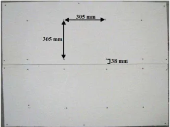
In the case of specimens L-5, L-6 and L-7, the gypsum board was attached to 19 mm thick wood furring strips. The furring strips were attached around the perimeter of the CLT and spaced 406 mm on centre starting from one edge. Specimens L-8 and L-9 included two layers of gypsum board. L-8 had a joint on the inside layer of the gypsum board and L-9 had a joint on the outside layer of gypsum board. The joint was located midway along one of the 914 mm dimensions and ran the full length (Figure 1). The gypsum board was then attached to the furring strips with 57 mm Type S screws every 305 mm along the furring strips. The heads of the exposed screws were covered with joint compound, and any exposed joints were taped and covered with joint compound prior to testing. The intumescent coating was a single component, water-based fire retardant applied at 92 wet mils (just over 60 dry mils).
Figure 1: Gypsum board joint configuration for specimens L-8 and L-9
The specimens were instrumented with thermocouples which allowed the monitoring of the performance of the protective membrane and the charring of the CLT panel. A temperature of 300ºC is considered an indicator of the base of the char layer [21]. Thermocouples were located on the exposed specimen surface, between gypsum board layers and the CLT surface as well as at the first two
glue lines from the exposed surface. Thermocouples were installed within the specimens by drilling holes from the back/non-fire exposed surface. The thermocouple depths were calculated by subtracting the depth of the holes from the 175 mm thickness of the CLT panel. The thermocouples were made at FPL from 24 gauge, Type K glass insulated thermocouples wires (Omega Engineering, INC., GG-K-24-SLE). The thermocouples located within the specimen were aligned on a 457 mm by 457 mm grid pattern centered on the specimen and spaced 76 mm apart.
FPInnovations Specimens
The FPInnovations specimens were constructed from commercially-available CLT panels (Nordic Structures X-Lam, stress grade E1), which are manufactured from spruce-pine-fir species—composed of 90% black spruce (Picea mariana). Each specimen was constructed with three, 35 mm thick plies. The specimens measured 1140 mm by 1970 mm by 105 mm. The CLT panels were left to acclimatise under ambient temperature conditions inside the NRC fire lab before specimen construction began. A summary of the FPInnovations specimens is given in Table 2 [22].
Table 2. Summary of FPInnovations specimens
Specimen Configuration
I-1 Exposed, no encapsulation
I-2 1 layer GB, 300 mm screw spacing, 57 mm Type S screws I-3 1 layer GB, 300 mm screw spacing, 76 mm
Type S screws I-4 1 layer GB, 205 mm screw spacing, 57 mm Type S screws
I-5 76 mm rock fibre, 89 mm Type S screws
and washers
I-6 51 mm rock fibre, 86 mm Type S screws
and washers
I-7 1 layer GB on 13 mm resilient channels
I-8 1 layer GB on 13 mm resilient channels, cavity filled with glass fibre insulation I-9 1 layer GB on furring channels with sound isolation clips, 100 mm cavity I-10 1 layer GB on furring channels with sound isolation clips, 100 mm cavity filled with 76 mm rock fibre insulation
I-11 83 mm SFRM applied onto wire mesh
stapled to CLT For the specimens with gypsum board, 16 mm Type X gypsum board was used. Specimen I-2 was constructed according to the CLT Handbook, which suggests using 57 mm long screws installed with a standard screw spacing of 305 mm on center [14, 15]. As wood chars, it loses its structural capacity and, therefore, its ability to hold screws in place. Therefore, specimen I-3 used 76 mm screws to evaluate whether a greater penetration depth would increase the time over which wood has the ability to hold screws in place. Test I-4 used decreased screw spacing, which is expected to allow the gypsum board to remain in place for longer fire exposures
because there is less area and weight bearing on each screw. For all specimens that used gypsum board as an encapsulation method, the screw heads were covered with drywall compound.
Specimens I-5 and I-6 used rock fibre made from basalt rock and slag, which is traditionally used for exterior wall applications. The rock fibre had a density of 128 kg/m3 and is non-combustible with a melting point
of 1177ºC. The rock fibre was held in place with 89 mm screws with 40 mm diameter washers. Pilot holes were drilled 38 mm into the rock fibre so that the washers and screw heads could be covered and protected by the cored out material.
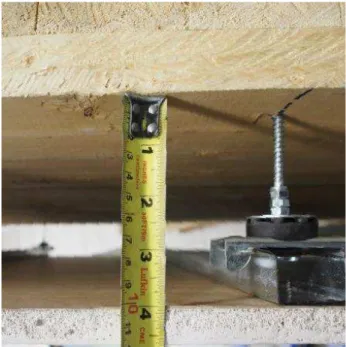
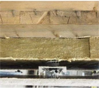
Four configurations with cavities were tested. I-7 included resilient channels that were spaced 405 mm on centre and attached with 32 mm Type S drywall screws to create a 13 mm cavity. The gypsum board was adhered to the channels with 25 mm Type S drywall screws spaced at 305 mm on centre. I-8 was identical to I-7, but included the addition of 13 mm fiberglass insulation into the cavity. Specimens I-9 and I-10 (Figures 2 and 3) used an increased cavity depth of 100 mm. The deeper air gap was created using sound isolation clips with additional spacers. The sound isolation clips were mounted onto wood lag screws, which were embedded 38 mm into the CLT. The holes were pre-drilled to allow for easier installation. The sound isolation clips were spaced at 406 mm by 610 mm. Twenty-two mm thick furring channels were hung from the clips and 16 mm Type X gypsum board was attached to the channels, which created a 100 mm cavity between the back of the gypsum board and the CLT. The 100 mm cavity in I-10 was filled with 76 mm of rock fibre insulation.
Figure 3: Specimen I-10 with 100 mm cavity filled with 76 mm rock fibre insulation
The SFRM used on specimen I-11 was a medium-density (240 kg/m3) Portland cement based product
(Figure 4). SFRM is commonly used for structural steel and concrete assemblies. However, there is no known published literature on its performance with mass timber assemblies. Based on Harmathy’s rule No. 6 [23], since SFRM has a low thermal conductivity, encapsulation should improve the fire resistance of the assembly and may be particularly useful when protecting concealed spaces.
Figure 4: Specimen I-11 with SFRM
In order to determine when charring of the fire-exposed CLT surface started, the CLT panels were instrumented with five thermocouples made from 24 gauge Type K glass-insulated thermocouple wire (TE Wire & Cable LLC G/G-24-KK) across their surface, the locations of which are illustrated in Figure 5. The CLT samples had three thermocouples embedded halfway into the first ply, 17.5 mm from the face of the panels, placed at similar locations to the surface thermocouples. The objective of this test series was to evaluate the encapsulation time provided by various methods of protection and not the char rate of CLT.
Figure 5: FPInnovations sample specimen assembly details
METHODOLOGY Fire Exposure
All twenty-three (23) specimens were tested in intermediate-scale horizontal furnaces and subjected to the same standard time-temperature curve specified in ASTM E119 [24] and CAN/ULC-S101 [25]. Specimens L-1 through L-12 were tested at FPL. The furnace at FPL is heated by eight diffusion-flame natural gas burners on the floor of the furnace. The interior dimensions of the furnace are 1.83 m long, 1.09 m wide and 1.27 m high. A frame was used to hold the panels and included two non-combustible inserts on each side of the specimen. The test frame with the test specimen was placed on top of the furnace. All air for combustion was provided by natural draft through vents at the bottom of the furnace. Six capped furnace thermocouples were located 305 mm from the fire-exposed specimen surface.
Specimens I-1 through I-11 were evaluated in an intermediate-scale furnace at the NRC fire laboratory in Ottawa, ON. The furnace at the NRC fire laboratory is constructed with steel framework, lined with two layers of insulating firebricks and has inside dimensions of 1.81 m long, 1.19 m wide and 0.52 m high. The furnace works on a fixed combustion air system with gas modulated to achieve furnace temperatures according to the required time-temperature profile.
Test Termination
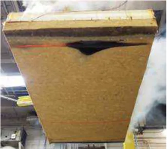
The FPL tests were terminated after the thermocouples at 105 mm from the fire-exposed surface reached 300ºC. At the conclusion of the tests, the specimens were removed, the fire was extinguished and visual observations of the specimens were made. The size of the specimen and available crane allowed the specimen to be removed shortly after termination of the test (Figure 6). Photographs were taken of residual specimens and some residual material thickness measurements were made.
For the FPInnovations specimens, most of the tests were terminated when a 600ºC criterion at the protected face of the CLT was reached. This limit represents a typical temperature when directly applied Type X gypsum board starts experiencing falling off.
Figure 6: Specimen removal from furnace
RESULTS
ENCAPSULATION TIME
For mass timber assemblies, encapsulation time represents a delay in the onset of charring, and therefore a delay before any wood element becomes involved and contributes to fire growth. Table 3 presents the encapsulation times and is organized based on specimen configuration. Encapsulation time in this paper is defined as the time for the exposed surface thermocouples to reach an average increase in temperature of 250ºC or a single point increase of 270ºC, whichever is less. Various literature states that wood begins to char at 300ºC. Therefore, the encapsulation times presented here are considered to be conservative estimates of charring initiation and coincide with the time at which thermal degradation of wood begins. The CLT panels with a single layer of 16 mm Type X gypsum board directly applied had an average encapsulation time of 26.5 minutes. Specimens I-3 and I-4 with longer screws and decreased screw spacing resulted in less than 1% change in encapsulation time. For the five CLT panels with a single layer of Type X gypsum board indirectly attached with a cavity and no insulation (L-5, L-6, L-7, I-7 an I-9), the average encapsulation time was 29.1 minutes; an increase over the average for directly attached gypsum board of 9%. For the panels with two layers of 16 mm Type X gypsum board directly applied, L-8 with the joint on the inside layer and the L-9 with the joint on the outside, the average encapsulation time of the two was 70.7 minutes, with very small differences in encapsulation time. The three layers of 16 mm Type X gypsum board afforded an encapsulation time of 130.4 minutes. For the specimens with intumescent coating, encapsulation times of 31.2 minutes for specimen L-11 and 21.1 minutes for
specimen L-12 were extrapolated from the temperatures within the CLT to the surface.
Table 3. Encapsulation times in minutes for protective
membranes
Configuration Specimen Encapsulation
Time (min) 1 layer GB, standard
screw length and spacing
L-3 27.7
L-4 26.3
I-2 25.4
1 layer GB, longer screws I-3 24.5
1 layer GB, tighter screw spacing
I-4 25.5
1 layer GB, 13 mm cavity I-7 26.3
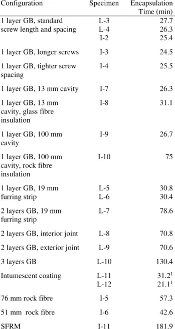
1 layer GB, 13 mm cavity, glass fibre insulation I-8 31.1 1 layer GB, 100 mm cavity I-9 26.7 1 layer GB, 100 mm cavity, rock fibre insulation I-10 75 1 layer GB, 19 mm furring strip L-5 30.8 L-6 30.4 2 layers GB, 19 mm furring strip L-7 78.6
2 layers GB, interior joint L-8 70.8
2 layers GB, exterior joint L-9 70.6
3 layers GB L-10 130.4
Intumescent coating L-11 31.21
L-12 21.11
76 mm rock fibre I-5 57.3
51 mm rock fibre I-6 42.6
SFRM I-11 181.9
1 These values were extrapolated from the temperature data in
the first ply.
The CLT panels covered with 51 mm and 76 mm of rock fibre had greater encapsulation times than those obtained with a single layer of 16 mm Type X gypsum board, reaching 42.6 and 57.3 minutes, respectively. The longest encapsulation time was obtained with 83 mm of SFRM at 181.9 minutes.
CHAR RATE
The main data collected to obtain charring rates is the temperature at the thermocouples embedded in the CLT specimens tested at FPL. The key experimental results of interest are the times for a temperature of 300ºC to be reached at the CLT surface and at the first glue line,
35 mm from the exposed CLT surface. A sample of the thermocouple data during a test is shown in Figure 7.
Figure 7: Temperature profile for specimen L-1 with no encapsulation
The temperature at the base of the char layer is generally considered to be 300ºC. With this temperature criterion, empirical equations for charring rate have been developed. The linear char rate of the first ply was calculated as the time it takes, after the surface reaches 300ºC, for the first glue line to reach 300ºC divided by the thickness of the ply (35 mm). To easily compare these times, the time at which the surface of the CLT reached 300ºC was subtracted from all temperature curves. A simple linear char rate is generally assumed for solid wood directly exposed to the standard fire [20]. The linear model for charring is:
c
Cx
t (1)
where t is time (min), C is char rate (min mm-1), and x c is
char depth (mm).
The non-linear model from the US CLT Handbook accounts for the accelerated charring of wood that occurs early in the fire exposure [14]. This non-linear model is:
23 . 1 39 . 0 x t (2)
where is the char rate (mmmin-1) and x is the char
depth (mm). The 0.39 factor presented here converts from units of hours to minutes.
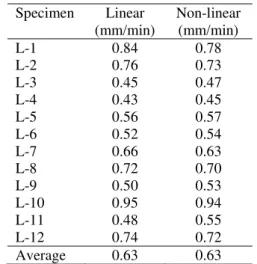
An average nominal char rate of 0.635 mm per minute is an accepted value for solid sawn and glue laminated softwood members [20]. Both the linear and non-linear char rates obtained from thermocouple data for specimens L-1 through L-12 are presented in Table 4. The average rate from both the linear and non-linear approaches is 0.634 mm/min. It should be noted that the adhesive used was affected by heat delamination around 230oC which would result in increased char rate
compared to solid timber.
Table 4. Linear and non-linear char rates (mm/min) of CLT
Specimen Linear (mm/min) Non-linear (mm/min) L-1 0.84 0.78 L-2 0.76 0.73 L-3 0.45 0.47 L-4 0.43 0.45 L-5 0.56 0.57 L-6 0.52 0.54 L-7 0.66 0.63 L-8 0.72 0.70 L-9 0.50 0.53 L-10 0.95 0.94 L-11 0.48 0.55 L-12 0.74 0.72 Average 0.63 0.63
DISCUSSION
ENCAPSULATION TIMEBased on previous research, a single layer of 16 mm thick Type X gypsum board was expected to provide approximately 30 minutes of protection to CLT, while two layers of 16 mm Type X gypsum board were expected to protect CLT for approximately 60 minutes, which agrees with the results of this study [7, 26]. While the addition of an air gap or cavity typically improved encapsulation times; the char rate of the first ply was greater with a cavity present when compared to the single layer of gypsum board directly applied to the CLT. This is possibly due to greater CLT surface area exposure to high temperatures as soon as a crack forms. The rock fibre insulation performed well. Since there is no known fire test data available on this type of product used in a horizontal application, the suitability of the attachment method was uncertain, but the insulation held in place very well and showed no signs of falling off even as the assembly was removed from the furnace (Figure 8). Given that the fire tests presented herein were of an intermediate scale, it is uncertain whether the method of attaching the insulation to the CLT would be sufficient when tested at a larger scale. Nevertheless, while the wood had begun charring, during deconstruction, some force was needed to pull off the rock fibre, indicating that its integrity was still maintained after fire exposure.
Figure 8: Specimen I-5 after removal from furnace
Specimen I-9 used sound isolation clips to create a 100 mm cavity between the CLT and a 16 mm Type X gypsum board. During the first 25 minutes of the test, the CLT surface temperatures of this assembly remained consistent with those of specimens I-7 and I-8 that had 13 mm cavities. After this time, however, the CLT surface followed a similar surface temperature curve to that of the specimens with one layer of gypsum board directly applied to the CLT, but at temperatures roughly 25ºC lower. This continued until 65 minutes into the test, when the rate of temperature increase abruptly changed, at which point the gypsum board is assumed to have fallen off (Figure 9).
Figure 9: CLT face temperature comparison
The encapsulation time of the SFRM assembly was 182 minutes. The SFRM manufacturer recommended a curing time of 40 days before standardized fire testing. However, due to time constraints, the assembly was only cured for 20 days before testing. While the sample appeared dry from the exterior, it is difficult to know the core condition of the assembly, which presumably would take the longest to cure. If residual moisture was present in the SFRM, the test may be representative of a situation in which a building is under construction and the SFRM has not yet fully cured. Having additional
moisture in the SFRM could potentially affect the bond between materials, which could have a negative impact on the results, or alternatively, the additional moisture could add to fire performance as it may cool the specimen as the water is driven off during exposure to heat. The SFRM remained completely intact during the test; the test was stopped after four hours of standard fire exposure. The SFRM was very effective at not only delaying the onset of charring, but also limiting the involvement of the CLT after it had begun to char, i.e. it insulated the wood very well. For the first two hours of testing, temperatures at the CLT surface did not exceed 100ºC. After two hours, the temperature began to increase more quickly, but still at a much slower rate than in all previously tested assemblies, until the onset of charring after three hours.
CHAR RATE
Inspection of Table 4 shows that the linear and non-linear char rates follow the same trends with respect to the method of encapsulation. Specimens L-3 and L-4, with one layer of 16 mm Type X gypsum directly applied, exhibited the lowest char rates. Specimens L-5 and L-6, with one layer of gypsum installed on furring strips, had a slightly higher char rate than the assemblies with one layer of gypsum directly applied. This increase may in part be due to more of the CLT surface being exposed to hot gases after the gypsum cracks. The gypsum that was installed on furring strips was also constrained differently than the one directly applied, with a different number and spacing of screws used which may have had an effect on when and how the gypsum layer failed.
The three tests that had two layers of 16 mm Type X gypsum had similar or slightly higher char rates than the specimens with one layer of the same gypsum board installed on furring strips. This may be explained by the increase in furnace temperatures associated with increased encapsulation times for the two layers of gypsum. The time-temperature curve followed by the furnace in these tests increases slowly with time, so the protection provided by the encapsulation is balanced by the higher char rates associated with higher temperatures. However, even with increased char rates in the first layer of the specimen there is an overall improvement due to the increased time before charring occurs. This is best exemplified by specimen L-10 that had three layers of 16 mm Type X gypsum directly applied. The measured linear char rate was 0.949 mm/min compared to an average of 0.799 mm/min for the un-protected specimens, a substantial increase. However, it took 163 minutes from the initiation of the test for the char front to reach the first glue line in specimen L-10 (3 layers of gypsum) compared to an average of 46 minutes for L-1 and L-2 (no encapsulation).
The effect of the intumescent coating on the char rate is not clear with specimen L-12 being similar to the unprotected specimens and L-11 exhibiting a lower char rate. This inconsistent performance was also seen in the
estimated encapsulation times. It is possible that a minor difference in applied thickness or other uncontrolled parameter had a large effect on these results.
CONCLUSIONS
Twenty-three (23) CLT assemblies using different encapsulation methods were tested in intermediate-scale furnaces and exposed to the standard fire curve in ASTM E119 and CAN/ULC-S101. The results of the tests were analyzed to determine the encapsulation time of the assemblies, which was defined as the time at which either the average temperature rise at the CLT surface exceed 250ºC or a single point rise exceeded 270ºC, whichever is less. The effect of the various encapsulation methods on the char rate through the first layer was also analyzed. The results of these tests have led to a better understanding of the fire performance of potential encapsulation methods used to increase the fire resistance of CLT assemblies. The results suggest that encapsulation methods considerably delay the time at which wood elements become involved in fire and have a substantial effect on char rate.
The specimens encapsulated with gypsum board performed as expected and results were comparable to those of previous research [7, 26]. Rock fibre insulation was able to improve encapsulation time by nearly 20 minutes over a standard Type X gypsum board application, and stayed in place for over two hours. SFRM provided the overall greatest encapsulation time. This product also stayed in place for four hours, at which time it showed no signs of imminent failure. This type of SFRM application is effective at delaying the onset of charring, reducing the rate of temperature rise within the wood surface, and further research is warranted for its applicability to complex designs and concealed spaces. Additionally, it is suggested that further testing be conducted with thinner applications of SFRM to determine the encapsulation time. It would also be interesting to investigate a direct application of SFRM onto CLT, without the use of a wire mesh or potentially with a simple surface adhesive coating, to evaluate the adhesion/bond between the materials under fire exposure.
ACKNOWLEDGEMENT
The authors thank the British Columbia Forestry Innovation Investment program for the financial support and the contribution of NRC laboratory staff that were instrumental in constructing the assemblies and conducting the FPInnovations’ experiments. Additionally, we thank the Southern Virginia Higher Education Center and the Department of Sustainable Biomaterials at Virginia Tech for their material support.
REFERENCES
[1] E. Karacebeyli and B. Douglas, CLT Handbook - US Edition, Quebec: FPInnovations, 2013.
[2] R. Gerard, D. Barber and A. Wolski, “Fire Safety
Challenges of Tall Buildings - Phase 1 Final Report,” The Fire Protection Research Foundation, Quincy, 2013.
[3] A Cooperation, “Fire Safe Use of Timber in Construction Seminar Seeks to Remove Outdated
Regulations,” [Online]. Available:
http://www.apec.org/Press/News-Releases/2005/0526_firesafepost.aspx. [Accessed 14 3 2016].
[4] ICC, 2015 International Building Code, International Code Council, IL: International Code Council, Inc., 2104.
[5] 2010 NBC, National Building Code of Canada, Ottawa, ON: National Research Council Canada, 2010.
[6] E. Karacabeyli and C. Lum, “Tall Wood Buildings in Canada: A Technical Guide for Design and Construction,” FPInnovations, Vancouver, BC, 2013.
[7] R. White, “Fire Resistance of Wood Members with Directly Applied Protection,” Wood Design Focus, vol. 19, no. 2, pp. 13-19, 2009.
[8] M. Feng, Y. Wang and J. Davies, “Thermal performance of cold-formed thin-walled steel panel systems in fire,” Fire Safety Journal, vol. 38, no. 4, pp. 365-394, 2003.
[9] J. Mehaffey, P. Cuerrier and G. Carisse, “A model for predicting heat transfer through gypsum-board/wood-stud walls exposed to fire,” Fire and Materials, vol. 18, no. 5, pp. 297-305, 2004. [10] L. Osborne, C. Dagenais and N. Benichou,
“Preliminary CLT Fire Resistance Testing Report,” FPInnovations, Quebec City, QC, 2012.
[11] L. Osborne, “CLT Fire Resistance Tests in Support of Tall Wood Building Demonstration Projects,” FPInnovations, Ottawa, ON, 2014.
[12] NGC, “Cross-Laminated Timber and Gypsum Board Wall Assembly (Load-Bearing) - Test Report WP-1950,” NGC Testing Services, Buffalo, NY, 2012.
[13] ANSI/APA, PRG 320 Standard for Performance-Rated Cross-Laminated Timber, Tacoma, WA: APA – The Engineered Wood Association, 2012. [14] C. Dagenais, R. White and K. Sumathipala, “Fire
Performance of Cross-Laminated Timber
Elements,” in CLT Handbook (US Edition), Pointe-Claire, QC: FPInnovations, 2013.
[15] C. Dagenais, “Fire Performance of Cross-Laminated Timber Assemblies (revised),” in CLT Handbook; Canadian Edition, Quebec, QC: FPInnovations, 2014.
[16] American Institute of Timber Construction (AITC), AITC 405 Standard for Adhesives for Use in Structural Glued Laminated Timber, Centennial, OH: American Institute of Timber Construction, 2005.
[17] National Institute of Standards and Technology (NIST), Voluntary Product Standard PS 1-09
Structural Plywood, Gaithersburg, MD: National Institute of Standards and Technology U.S. Department of Commerce, 2009.
[18] D. Hindman and J. Bouldin, “Development of Southern Pine Cross-Laminated Timber for Buliding Code Acceptance,” in World Conference on Timber Engineering, Quebec City, 2014. [19] L. Gaby, “The Southern Pines,” USDA Forest
Service, Madison, 1985.
[20] British-Adopted European Standard, BS EN 520:2004+A1:2009 Gypsum plasterboards. Definitions, requirements and test methods.. [21] R. White and M. Dietenberger, “Fire Safety of
Wood Construction,” in Wood Handbook: Wood as an Engineering Material, Madison, WI: USDA Forest Products Laboratory, 2010.
[22] L. Osborne and A. Roy-Poirier, “Advanced Methods of Encapsulation,” FPInnovations, 2015. [23] T. Harmathy, “Ten Rules of Fire Endurance
Rating,” Fire Technology, vol. 1, p. 93, 1965. [24] ASTM E119, West Conchohocken, PA: ASTM
International, 2012.
[25] CAN/ULC S101 - Fire Endurance Tests of Building Construction and Materials, Ottawa, ON: Underwriters Laboratory of Canada, 2007.
[26] R. White, “Preliminary investigation of a three hours rated wood wall,” USDA Forest Products Laboratory, Madison, WI, 2011.
Home ›Abstracts & Full Papers
Abstracts & Full Papers
Fire safety of structures made of timber and other bio-based products - COST Action FP1404
MS4-08C: 5 Fire performance of mass-timber encapsulation methods and the effect of encapsulation on char rate of cross-laminated timber
Hasburgh, L. E.; Bourne, K. J.; Dagenais, C.; Osborne, L.; Roy-Poirier, A.
Abstract
Twenty-three (23) cross-laminated timber (CLT) panels were exposed to a standard fire at an intermediate scale. This paper discusses several encapsulation methods used to increase the fire resistance of those panels, with emphasis on encapsulation times and the impact of encapsulation on the charring rate of CLTs. The encapsulation methods used included Type X gypsum board, intumescent coating, rock fibre insulation and spray applied fire-resistant materials (SFRM). The results suggest that encapsulation methods can significantly reduce wood charring rates in addition to delaying the time at which wood elements become involved in fire.
View Abstract
Full Paper
View Full Paper
Citation
Hasburgh, L. E.; Bourne, K. J.; Dagenais, C.; Osborne, L.; Roy-Poirier, A.: Fire performance of mass-timber encapsulation methods and the effect of
encapsulation on char rate of cross-laminated timber, CD-ROM Proceedings of the
World Conference on Timber Engineering (WCTE 2016), August 22-25, 2016, Vienna,
Austria, Eds.: J. Eberhardsteiner, W. Winter, A. Fadai, M. Pöll, Publisher: Vienna University of Technology, Austria, ISBN: 978-3-903039-00-1
H
© WCTE 2016, Vienna, Austria 2016 / All Rights Reserved
Home Conference Info Ú Scientific ProgrammeÚ Abstracts & Full Papers Authors Search
Page 1 of 1
Hasburgh, L. E.; Bourne, K. J.; Dagenais, C.; Osborne, L.; Roy-Poirier, A.: Fire performa...
8/30/2016
file:///E:/E242_ZSERV_TUWIEN_AC/detail-1224.html
View publication stats View publication stats