DOE/PC-70512-10
Development and Test 6
an Internally Cooled, Cabled Supercon uctor (ICCS) for Large Scale MHD Magnets
Semiannual Progress Report
Period from January 1, 1987 to June 30, 1987 Hale, J.R., Marston, P.G., Dawson, A.M.
Plasma Fusion Center
Massachusetts Institute of Technology Cambridge, Massachusetts 02139, USA
This work was supported by the U.S. Department of Energy, Pittsburgh Energy Tech-nology Center, Pittsburgh, PA, 15236 under Contract No. DE-AC22-84PC70512. Repro-duction, translation, publication, use arid
disposal,
in whole or part, by or forthe
United States Government is permitted.NOTICE
This report was prepared as an account of work by an agency of the United States Government. Neither the United States Government nor any agency thereof, nor any of their employees, makes any warranty, express or implied, or assumes any legal liability or responsibility for the accuracy, completeness, or usefulness of any information, appara-tus, product, or process disclosed, or represents that its use would not infringe privately owned rights. Reference herein to any specific commercial product, process, or service by trademark, manufacturer, or otherwise, does not necessarily constitute or imply its en-dorsement, recommendation, or favoring by the United States Government or any agency thereof. The views and opinions of authors expressed herein do not necessarily state or reflect those of the United States Government or any agency thereof.
TABLE OF CONTENTS
Section 1.0 2.03.0
4.0 4.1 4.1.1 4.1.2 4.1.3 4.1.4 4.2 4.2.1 4.2.3 4.3 4.3.1 4.4 5.0Title
IntroductionReview of Technical Progress Prior to January 1, 1987 Summary of Technical Progress, January 1 to June 30, 1987 Technical Progress, January 1 to June 30, 1987
Stability and Performance Predictions Current Sharing
Stability Predictions
Discussion of Stability Predictions Discussion Of Energy Margin Plots Preparation for Subscale Conductor Tests The Test Rig
Instrumentation
Heater Specification and Prototype Preparation Heater Specification
Data Acquisition System References
Page No.
1 23
4
4
44
7
8
9
9
1011
1113
13
1.0 Introduction
A three-year program to develop and test an internally-cooled, cabled superconduc-tor (ICCS) for large-scale MHD magnets is being conducted by the MIT Plasma Fusion Center for the Pittsburgh Energy Technology Center (PETC) under Contract DE-AC22-84PC70512. The program consists of the following four tasks:
I Design Requirements Definition II Analysis
III Experiment IV Full-scale Test
This report summarizes the technical progress on Task III during the period from Jan-uary 1, 1987 to June 30, 1987. Progress in the preceeding periods has been described in a se-ries of semiannual and quarterly progress reports, in the Design Requirements Definition(') and the Analysis Report('). An independent Test Plan(') was submitted to the Pittsburgh Energy Technology Center (PETC) in the period covered by this report and was accepted by them.
As stated previously, the objective of Task III is to conduct an experimental test pro-gram on subscale ICCS conductors that were selected following evaluation of the results of Phases I and II of this contract. Two niobium-titanium (NbTi) subscale conductors of the ICCS type have been chosen as potential prototype candidates to use in winding the magnet for an MHD power-generation system. One of these conductors is composed of triplets in which each strand contains superconductor. The other candidate conductor under investigation contains triplets in which only one of the three strands contains super-conductor, while the other two strands are pure copper stabilizer only. If this latter design shows similar stability, quench propagation, and pressure dynamics performance as the other, more conventional design, it offers a potential significant savings in manufacturing cost for full-scale conductor.
This report documents the initiation of the subscale conductor test program on the two prototypical candidate conductors selected and defined in the previous report. It also documents additional analysis used to predict the behavior of these two candidate conductors.
2.0 Review of Technical Progress Prior to January 1, 1987.
Technical progress from the start of the program through June 30, 1987 is reviewed briefly as a framework for the report of progress contained in sections 3.0 and 4.0.
To initiate the preconceptual magnet design, it was assumed that a typical retrofit-scale MHD magnet would:
1. accommodate a supersonic MHD channel of about 35 MWe output, requiring a peak on-axis field of 4.5 tesla.
2. operate at a design current in the neighborhood of 25 kA.
It was assumed that the dimensions and construction of the conductor for the full-scale retrofit magnet would be the same as those of the ICCS conductor used in the large D-shaped magnet built by Westinghouse Corporation for the Large Coil Program tokamak TF coil study(',). This was done to take advantage of the manufacturing technology that had been developed for that project. The MHD conductor will use NbTi superconductor rather than Nb3Sn because of the difference in field requirement.
The retrofit magnet's size and field strength were selected based on information ob-tained by surveying the MHD community. A relatively high design current was selected in the interest of minimizing overall system cost('). The selection of overall ICCS dimen-sions and construction were aimed at minimizing conductor development time and cost by using a conductor size and construction for which production and tooling experience already exist.
An initial preconceptual design for a retrofit-scale magnet was generated that incor-porates a 600 rectangular-saddle-coil ICCS winding without substructure that will operate at a design current of 24 kA in a stainless-steel force-containment structure and cryostat.
A detailed computer analysis of the winding showed that maximum fields were about 7.2 T rather than the 6 T estimated. The winding was therefore modified to reduce the maximum field and to ensure stable operation. The resulting design had coils with increased thickness, increased end turn bend radius and lower current density, resulting in a magnet preconceptual design which compared favorably with earlier designs in reliability, manufacturability, and cost effectiveness.
Once this preliminary design was completed it was necessary to review and improve the preconceptual design and provide greater detail. Electromagnetic analyses were re-viewed and checked using alternate approaches. Pressure drop and frictional heating in the conductor coolant circuit were checked, and a number of critical structural details were reviewed and analysed further. Completion of that work provided a sound basis for
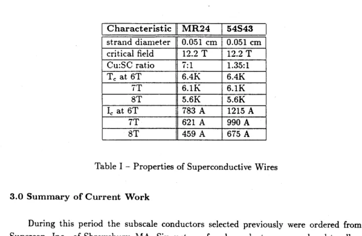
establishing conductor design requirements and defining the experimental test program. In the report for the period Julyl to December 31, 1986, the two candidate conductors to be used in the subscale conductor test program were identified, and some of the analysis that led to their selection was described in considerable detail. The subscale conductors selected are each 3x3x3 cables. In type A all strands contain superconductor, whereas in type B only one strand in each of the nine triplets contains superconductor. The characteristics of the superconductive strands are reviewed in Table I.
Characteristic MR24 54S43 strand diameter 0.051 cm 0.051 cm critical field 12.2 T 12.2 T Cu:SC ratio 7:1 1.35:1 T, at 6T 6.4K 6.4K 7T 6.1K 6.1K 8T 5.6K 5.6K I at 6T 783 A 1215 A 7T 621 A 990 A 8T 459 A 675 A
Table I - Properties of Superconductive Wires
3.0 Summary of Current Work
During this period the subscale conductors selected previously were ordered from Supercon, Inc., of Shrewsbury, MA. Six meters of each conductor were ordered to allow both for the ultimate long-sample test of each and to have adequate conductor for the necessary preliminary bending and assembly tests.
The test plan was rewritten to take into account DOE/PETC's comments,O) and the conceptual design of the test rig for the long-sample tests was revised to improve the efficiency of the tests. A number of preliminary bending tests were conducted. The test heater was procured and a number of tests were performed on it, including bending tests, soldering tests, and measurements of performance.
In addition to the above, the analytical work on these subscale conductors continued, with particular emphasis on stability predictions.
4.0 Technical Progress from January 1, 1987 to June 30, 1987
4.1 Stability and Performance Predictions
4.1.1 Current Sharing
Figures 1 through 3 show plots of calculated current-sharing temperature as a function of operating current for three values of field strength in the range over which tests will be conducted. The calculation is based on the simple linear approximation
TC = Tc
- '7(TTb)
IC
where I, is the critical current at the bath temperature, and T is'the bath temperature.
4.1.2 Stability Predictions
The program used for these predictions is designed to simulate the time history of temperature and pressure in an ICCS following the application of an energy pulse to the
entire volume of wire in a test coil. The coil is considered to be a closed system with no net
helium flow into or out of the coil during the event. The energy margin of the conductor for the case of a perturbation being deposited in the whole of the conductor is another useful output of this program.
In an ICCS MHD magnet system, as in any superconducting magnet, the wire will be vulnerable to energy perturbations that raise its temperature to - and beyond - the current-sharing level. But unlike the case in some applications, in an MHD system the energy impulse is likely to be generated at the surface of the sheath, as a result of motion-induced frictional heating, rather than within the strands. How, then, may the stability program be used as it was designed for use in the latter case, but is needed for analysis of the former? The best use to which this program can be put is to calculate the upper limits of energy margin. The most significant difference between the computer model and the actual test configuration lies in the physical extent of the applied energy perturbation, being uniform throughout the model, and relatively local in the test.
The degree to which the calculated values of energy margin agree with those that are measured, all else being equal, will depend on the path taken by the applied energy pulse from the start of the sheath where it originates to the strands. If, on the one hand, the heat flows from the high-temperature sheath directly to the strands by conduction, the
situation is similar to the one in which the energy is deposited in the strands directly. These characteristics would apply:
* The temperature of the helium lags that of the strands.
* No nonrecoverable normalcy can occur unless the energy perturbation raises the temperature of the sheath and the strands beyond the current-sharing temperature at the very least.
* Recovery can occur in some cases, even if the temperature of the strands exceeds the current-sharing temperature briefly, because the helium may still be cold enough to accept enough heat from the strands to cool them to below the current-sharing temperature, in spite of the joule heating that takes place during the brief current-sharing episode.
* The energy required to drive a nonrecovery event is supplied chiefly by joule heat-ing. This source of energy, a consequence of current-sharing, vastly exceeds the energy perturbation that initiated the event.
e If the helium temperature reaches the current-sharing temperature, recovery is not possible.
If, on the other hand, the heat generated in the sheath flows principally into the helium, these characteristics would apply:
" The temperature of the helium leads the strands.
" No nonrecoverable normalcy can occur unless the energy perturbation raises the temperature of the sheath and the helium beyond the current-sharing temperature at the very least.
* Recovery can never occur if the temperature of the strands exceeds the current-sharing temperature even briefly, because it is by immersion in the warmer helium that the temperature of the strands has been raised, and hence, only after the helium has exceeded the current-sharing temperature will the strands do so. There is nothing cooler to which the strands can transfer heat, and hence, current-sharing grows unabated.
* The energy required to initiate a nonrecovery event must be supplied wholly by the initial perturbation.
* If the helium temperature reaches the current-sharing temperature, recovery is not possible.
The one characteristic that is common to these two scenarios is that nonrecovery is inevitable only if the temperature of the helium is driven beyond the current-sharing temperature. The most significant difference between the two is that in the first case the initial perturbation is but a small fraction of the total energy required to raise the
helium temperature to this level, while in the second, the initial perturbation alone must be sufficient to heat the helium to that temperature, other factors being equal. That is, while the amount of energy required to reach the nonrecovery point is the same for both cases, being equal to the enthalpy difference
Hiiil- Hcurrent-sharing
for all participating materials in the conductor, joule heating supplies most of the energy
in the first case, and the initial perturbation supplies all of it in the second. The subscripts above refer to the temperatures that correspond to the two values of enthalpy.
Which case is more nearly representative of the test configuration is not yet known. For this reason "worst case" calculations have been carried out for both extremes for both conductors. The first "worst case" scenario is defined as follows:
* The perturbation is applied to the full length of the conductor. The heat flow by conduction directly from the heated sheath to the strands is such that the temperature distribution at a time Ati following the perturbation is nearly identical to that following the application of the same energy impulse directly to the strands throughout the entire length of conductor.
The second "worst case" scenario is defined this way:
* The heat transferred from the sheath is such that at a time At,, following the perturbation, the temperatures of the sheath, the helium, and the strands are all the same.
The criteria for defining the values of Ati and At,, are estimates at best: based on the time scales of events portrayed by the stability program values can be set within the range from one to 20 milliseconds.
If the first scenario applies, the temperature of the strands rises much more quickly than that of the helium, and an upper limit for the energy margin of the conductors can be obtained by multiple runs of the program. If, on the other hand, the second scenario applies, the temperature of the strands significantly lags that of the helium. The upper limit of the energy margin will be equal simply to Hinitial - Hcurrent-sharing for all participating materials in the conductor, including the helium.
Common to all the calculations done by the stability program were the dimensions and physical characteristics of the conductor strands that were presented in Table I above. Moreover, the parameters listed below were consistent throughout the series of calculations made with this program:
9 Initial Pressure.. .3 atm
"
Initial Temperature.. .4.2 K* Energy Perturbation... A single half-sinusoidal pulse of 20 ms duration
" Heat transfer from strands to helium was not a constant: that is, it was a function of temperature, pressure, and density and was computed at each time step of the calculation.
The results from the program are as follows: Type A Conductor
Figure 4 plots the upper limit of energy margin for the Type A subscale conductor for worst case I, for three values of background magnetic field. Figure 5 is a plot for worst case II. In order to facilitate comparison, the two sets of data are plotted together in Figure 6. As expected, the energy margin for worst cases II in which the perturbing impulse must supply all of the energy that leads to nonrecovery, is for the most part larger than for worst case I, in which current-sharing takes place.
Type B Conductor
Figures 7, 8, and 9 are the counterparts of Figures 4 - 6, respectively, for Type B conductor. The results from type B conductor are clearly different from those for type A. This issue is addressed in more detail below. The principal reason for the large difference between worst case I and worst case II is that the stability program has no provision for hybriding of the strands in a cable. The computer model for case I, therefore, was built with only the nine 54S43 strands. That is, the pure copper strands were assumed to be innocuous both electrically and thermally during the short interval of time during which the event occurred. Joule heating during current sharing was therefore more severe because of the low copper:noncopper ratio of the strands. For case II, on the other hand, all 27 strands contributed enthalpy, raising the energy margin to values much higher than for case I.
4.1.3 Discussion of Stability Predictions
Thermal Properties
The data are presented in units of energy per unit length, taking into account the proportions of the constituents from which these actual conductors were made. Two sim-plifying assumptions were made: the density of the helium was constant, and the strands were taken to be all-copper as far as specific heat was concerned.
Implications
The helium, occupying the 35% void space, accounts for nearly all of the enthalpy in these conductors in the temperature range of interest, about 95%, while the strands account for only about 0.3-0.4% of the total. This fact may have a bearing on which of the worst case models is more credible. If, for example, the heat transfer rate, in watts, from the heated sheath to the helium is two orders of magnitude greater than the transfer by conduction to the strands, the temperature rise in the strands will lead to
the temperature rise in the helium. This scenario, if accurate, lends support to the view
that energy perturbations at the sheath will yield outcomes much like those in which the perturbations occur within the strand material itself. The existing stability program, then, would prove to be more credible than expected in analyzing such test configurations: the worst case I data generated with that program may prove to be better indicators of the true upper limit than are the worst case II data.
4.1.4 Discussion of Energy Margin Plots
Type A Conductor
Referring to Figure 6, one notes that, except for the puzzling case of the crossover in the 8 T data, worst case II margins are higher than worst case I margins. The difference between them is larger at lower operating currents. The reason for this lies in the fact that case I portrays a dynamic process, while the calculations for case II involve only enthalpy difference and no time dependence. At lower operating currents, the progression of the competition between current-sharing and heat transfer to the slowly warming helium takes place over a time interval that is longer than it is at higher currents. That is, the possibility of recovery or nonrecovery occurs more rapidly at higher currents. Consequently, the time integral of the joule heating is greater at lower currents than at high, which is to say that the initial perturbing energy impulse supplies a smaller fraction of the total at lower currents than it does at higher currents.
Despite the vast difference in the level of sophistication in the calculations for these two worst case upper limits, it is noteworthy that they differ at most by less than a factor
of two.
Type B Conductor
The stability program, as mentioned above, has no provision for modeling a hybrid cable. Therefore, the simplification was made that for the duration of the recovery/no-recovery "event," typically less than 60 ms (except at very low and hence uninteresting values of operating current), the all-copper strands would not participate electrically or
thermally. This simplified model comprised, then, nine strands of 54S43 wire contained in a smaller diameter sheath that had been sized to retain the same value of sheath mass per unit length, and the same helium mass per unit length as in the actual conductor.
The differences between energy margins computed for this model by the stability program (case I) and those calculated solely on the basis of enthalpy (case II) are as much as a factor of three, seen most conveniently in Figure 9. Although case II calculations included the enthalpy of the all-copper strands, that small amount of enthalpy cannot account for a factor of three. It is probable that the case I data were unrealistically depressed by the exclusion of the all-copper strands from electrical participation in current sharing. The small copper:noncopper ratio of the 54S43 strands yields a large voltage drop per unit length during current sharing, and hence, vigorous joule heating in the simplified nine-strand model. Test measurements may be interpreted to indicate the degree to which the all-copper strands participate electrically by whether the data fall closer to the pessimistic case I model or to the more optimistic case II.
In Figure 7 the curves describing energy margin at 6 T and 7 T displayed a curious knee, while the curve for 8 T did not. The simulation program for the cases 7.5 T and 8 T were rerun and it was found that the knee appears in both, the location shifting toward lower operating current for higher levels of background field. In earlier runs, the value of operating current was never set to a small enough value to reveal the knee in the higher field data. It is possible, but as yet unverified, that this may be related to the sharp peak in the value of specific heat of helium at 3 atmospheres, between about 5.4 K and 6 K.
4.2 Preparation for Subscale Conductor Tests
To ensure the successful construction of the long-length test rig for the subscale con-ductors it was necessary to conduct a number of preliminary tests and prepare a number of prototypes. These are described in detail in the following sections.
4.2.1 The Test Rig
The test rig design was modified during this period to allow both subscale conductors to be wound onto a single spool. The new winding is in the form of a double helix. The two conductors will be joined electrically and hydraulically at one end. Therefore there will be just two current leads and two hydraulic connections. The initial plan has been to energize both conductors while testing only one at a time. If circumstances warrant, a third current connection may be added at the center tap where the two are joined.
The conductors will be wound in a single layer in thread-like grooves cut into a G-10
cylindrical mandrel. The grooves will obviate turn-to-turn insulation, and so the surface
of the conductor sheath will be accessible for attachment of heaters and instrumentation
leads.
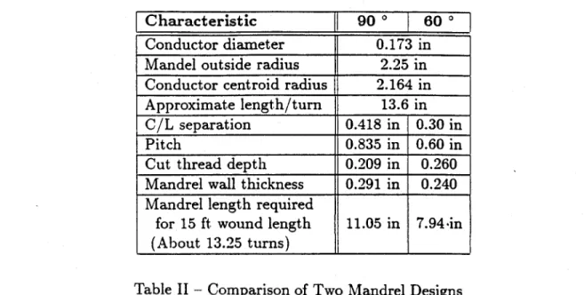
Table II shows the gross characteristics of two alternatives for the design of the MHD
subscale test conductor winding.
Table 1I
-
Comparison of Two Mandrel Designs
The included angle has been selected as 600, keeping the overall length of the package
reasonably short. The overall length of the mandrel will be about 10 inches; one inch
at each end will have no threads, and double-helical threads will be machined into the
remaining eight inches. The 'valleys' of these threads will be concave to fit the o.d. of the
conductor.
Terminations
The two free ends will both be terminated with a standard stainless-steel weld tee,
with adaptors fitted as required
-
one to receive the conductor sheath, one for a copper tube
in which the bared strands have been swaged, and a third one for hydraulic connections.
The two conductors will be joined in a single fitting, a standard stainless-steel pipe weld
union, at the opposite end of the assembly. A double-bore adaptor at one end of the
union will accept both conductor sheaths. Electrical continuity will be achieved within
the copper tube, while hydraulic continuity will be realized within the union. The copper
tube containing the bared swaged strands will extend for 6 to 8 inches beyond the winding
mandrel, but the experimental Dewar can accommodate as much as 33 inches.
Characteristic
l900
*1 60Conductor diameter 0.173 in Mandel outside radius 2.25 in Conductor centroid radius 2.164 in Approximate length/turn 13.6 in C/L separation 0.418 in 0.30 in
Pitch 0.835 in 0.60 in
Cut thread depth 0.209 in 0.260 Mandrel wall thickness 0.291 in 0.240 Mandrel length required
for 15 ft wound length 11.05 in 7.94-in (About 13.25 turns)
4.2.2 Instrumentation
Details of instrumentation are still being discussed. Among measurements that may be carfied out are:
* Voltage at several points along each conductor length, in order to detect normal zone propagation.
e Pressure vs. time measurement initiated following the onset of a normal zone, using a pressure transducer.
* Sheath temperature using a fast response time temperature sensor.
4.3 Heater Specification and Prototype Preparation
4.3.1 Heater Specification
The stability predictions that were discussed above were based upon computer model-ing of energy margin testmodel-ing. One important concept that was mentioned in that discussion was that nonrecovery from an energy perturbation is inevitable only if the temperature of the helium is driven beyond the current-sharing temperature. In the worst case, all of the energy necessary to achieve this condition must be delivered in the perturbation, with none of it generated by joule heating.
In order to select an ample means for applying a heat pulse, one first must calculate the required temperature rise, and the enthalpy of the sample. Figure 1 shows that at the lowest field level of interest, 6 T, the target temperature, T,,, will always be less than 6.5 K. The enthalpies of the three components of the conductor are plotted in Figure 11. The helium pressure is 3 atmospheres, and the enthalpy of the strands is assumed for this estimate to be the same as that of copper. From this plot, one can see that a pulse of about 0.15 J/cm,* or 4.5 joules over a length of 30 cm, would raise the temperature of the sheath, the strands, and the surrounding helium to about 7 K.
Next, the time scale of frictional events in magnets was investigated through conver-sations with Dr. Y. Iwasa, a noted authority in this field. He reported that they occur within the range 1 to 10 ms, most often in the faster portion of the range. The estimate of
* For these conductors, this corresponds to 2.7 J/cm3. As stated above, energy margins may be expected to be different for the case of a perturbation applied to the sheath surface, as opposed to one applied to the strands.
about 5 joules required to drive the subscale test conductor into nonrecoverable current-sharing was discussed. Dr. Iwasa made a rough calculation, based on a pressure of 30,000 psi pressure between adjacent square-cross-section conductors of about the same size as our round ones. The result, he reported, suggested that this amount of energy would be released in a slippage of 50 pm, which he said was in agreement with current understanding of such phenomena.
The task, then, was to devise a means of delivering at least 5 joules of energy to the conductor at the surface of the sheath, in simulation of a 1-10 ms slip event. The heater chosen is shown schematically in Figure 12. It is a commercially available unit measuring 0.040 inches in diameter. The outer jacket of the unit is Inconel 600. The resistance wires are insulated from the jacket with compacted MgO powder, with a dielectric strength of about 4 x 10⁶ V/m. The stainless-steel outer sheath is amenable to soldering, and excellent thermal contact will thereby be achieved between the heater and the conductor sheath. The resistance of this unit at 77 K is 30 Q.
There was some question about the voltage tolerance of the heater; a simple calculation revealed that to deliver 5 joules into 30 Q in 1 ms, a capacitor would need an intial voltage of 830 V. But the separation between the two resistance elements is only about 0.006 in., and the manufacturer seemed to indicate that the heater might withstand only 300-500 volts. A pulse duration of about 10 ms with a voltage of about 260 volts was selected. Another calculation indicated that the applied energy would not damage the heater even if the event was adiabatic; the calculation suggested that there would be a safety factor of 10. Nonetheless, an extra heater was purchased for use as a trial unit, to be tested to destruction if necessary to find its operating limit.
4.3.2 Heater Test
The heater test was combined with two others; first, the development of a technique for forming the test conductor into a helical shape; and second, the development of a technique for soldering the heater onto the helical sample. Approximately three feet of conductor were formed into a helical shape, and then mounted on a 4" diameter tube. Next, the heater was also formed into a helix, and soldered to the sheath of the sample. The techniques used for both these operations were quite satisfactory, and will be used for the full-scale assembly.
The sample was immersed in liquid nitrogen, and the heater was subjected to capaci-tive discharges from initial voltages as high as 450 V, the operating limit of the capacitors. Voltage traces from the capacitor, the sample, and a current shunt were digitized and stored by the computer, and displayed on the terminal screen. Other software allows these
transients to be redisplayed, and the traces to be converted to true volts and current; other transforms may be carried out as desired.
The total energy delivered in the most severe discharge was nearly 15 joules in 10 ms. No evidence of damage was seen, either in the device itself or in the displayed data traces. Even if the transfer of heat from the heater to the sheath is less than perfect, as is likely to be the case, the conductors can still be quenched. Great effort will be expended during assembly of the actual test apparatus to enhance the likelihood that most of the energy that is delivered to the capacitor will be transferred to the sheath. As stated above, it would be interesting to measure the temperature of the sheath, and of the interior of the conductor on a time scale of 10-20 ms during the capacitive discharge.
4.4 Data Acquisition System
The hardware and software for data acquisition, storage, and analysis have been in-stalled and tested ahead of schedule. Early completion of this data system provided an excellent opportunity to combine the scheduled test of the heater with the shakedown of the microVax-based data acquisition system.
5.0 References
1. Design Requirements Definition Report for ICCS for Large Scale MHD Magnets, Plasma Fusion Center, MIT, Cambridge, MA, November 1985.
2. Analysis Report, Develop and Test an Internally Cooled Cabled Superconductor
(ICCS) for Large Scale MHD Magnets, MIT, January 1986, DOE/PC-70512-5.
3. Develop and Test an Internally Cooled, Cabled Superconductor for Large Scale MHD Magnets: Test Plan, August 1986, revised May 1987, DOE/PC-70512-6.
4. Develop and Test an Internally Cooled, Cabled Superconductor for Large Scale MHD Magnets: Semiannual Progress Report, July 1, 1986 to December 31, 1986, DOE/PC-70512-9, September 1987.
5. C.J. Heyne, D.T. Hackworth, S.K. Singh, Y.L. Young, Westinghouse Design of a Forced Flow Nb3Sn Test Coil for the Large Coil Program, and references therein, Eighth Symposium on Engineering Problems in Fusion Research, pp 1148-1153, 1979. 6. P. A. Materna, Design Considerations for Forced-flow Superconductors in Toroidal
Field Coils, Tenth Symposium on Engineering Problems in Fusion Research, pp 1741-1746, 1983.
4 4 I I 4 I I I 4 4 I I 4 4 4 4 4 4 4 4 4 I 4 4 * I I I I a a I a a 4 I I 4 I 4 * I I 4 I 4 a a 4 I I I I * a a a * I I I 4 4 4 a a I I I a a I 4 4 I 4 ~ -' I 4 4 I I I I 4 I I a
/
I 4 4 a 4 4 I I I I 4 I I I 4 a 4 4 4 $ I I I I a a a 4 4 I I * I I I 4 a a 4 4 I 4 4 4 4 I I 4 I I I a -* I I I I I I C... 4 4 I I I I 4 4 4 4 a(f)
I I I 4 4 -H I 4 4 I 4 I 03 4 4 4 4 I (0 4 4 4 4 a 4 4 4 I I I - - - - 4.~ I- -I 403
0. CLE
03
. a i i 4 4 a I 4 4 4 4 I I I 4 I a i i I I I a C ) 4 4 I I (0 4 4 4 I C I 4 4 I I I I 4 4 4 I 4 4 4 I I I 4 4 4 9 I 4 Ia
I I I 4 4 (0 4 I 4 4 4 I0
I 4 4 4 4 I 4 I 4 4 4 4cJ-~
4 I 4 a 4 4 4 4 -4 4 4 4 I 4 -I- a I I I 4 I I 4 I h. 4 I 4 4 444. 4 4 4 4 4 4 I 4 4 4 4 I 4 I 4 4 4 4 4 4 I 4 I 4 4 a --- 4.----4.----4.----4.----4.----4.----4. .4 4 4 4 4 I I 4 4 4 4 I C-) 4 4 I I 4 4 I I 4 4 4 I 4 4 4 I 4 4 4 4 4 I 4 . 4 4 4 4 4 4 4 '...I...L...1...L...I...I...i...L...1...I 4 I I I I I I U) U) U) in CO tO U) U)[>1
Figure 1
I I I I I r T F -T--T- I I I I I C%-j - - - -- - - -- - - --- - - - --- - - -- - --- - - -- - - - -- - - -- -- - -
-I
- - - - - - - I - - - I - - - I - - - - --- -- --- ---L - - - ---L - - - ----I
CD U) c U D C-)0
Ln LnC-:
0
(A
Ln L sojD)
..
. IFigure 2
i I -- F
T-1 I I
---
---r
--- r
---cli
(U cu CD U) cu LD-- ---
---
---7
11
--- ---
--- --- --- --- --- - --- L --- L --- --- -- L ---m
3
L6 U')(16
Figure 3
-I. I r I I I~ I I I I I I I I a-i CD a (0 C-) ( 0
c.'
0 (.0 c ( E x x J3/rIJ)-
03-Figure 4
---- I----(0 I I II
I I I I I
I r, I - I I II
0
I I I I I I I -I I I I I I I I I/
I I I I I I 9 I w I I I I I I I I I S I I I I I I I I I I I I g I I I I I I I I I -I I I I I I I I I I I I I I I I I I I I -I I...-I I I I I I I I I I I I i (.0 I I I I I I I I I I I I I I I I I I I I I I I I I I I I I I I I I I I I I I I I I I I I I I I I I I I I I I I I I I I I I I I I I I I I I I I I I II!!!
I I III IIcli F-T I v cl: - - - - - - - - --- - - - --- -- --- --- --- --- --- --- --- --- --- I --- co 0 --- 4 CD
a
C-D - --- --- --- --- --- ---I --- r --- oo CD .z cm ------III lilt 1111 IILIIII IL11 III ILII 1111 111 1..
ao LO N m m 19
C
0
I I I II I I I I I I I I IN II I I I I I I I I II I -9---C -(0 C-20 C U, I I I I I I
I
cfl - I - I - I -- I.- I--I I I I II
CO cmFigure 6
Co Nm03
r -C. C\j I I I I I---cr
CL
C
I I I I I I I I I * I I I I I I I I I I * I I I I I I I I I I I I I I I I I I I I I I I I I I I I I I7
I I I I 1/ -I I I I IA
I I I I I I/
I I I I I I I * :-' / *1~~' I I / I I ~ 1' I I ,-I I I ,-I I - I I ~ - - I I I ----- 2
I I -I I ~I I I I I I I I I I I I I I I I I I I I I I I I I I I I I I I II II IlIllIll III cNC\j Cn
C)
(EmxW3/FW)
Figure 7
--- --- --- ----- - - -- -- - - --
-
--
---I
T T-
---cc
CD
a
>1
C-D
0
7
.. ...19
C-)
V
::D CD) tl111111111
I'
II'I
I I * I I I S 0 I I I I I * I I I I * - I I H I * I I I I I I I * I I I I I I I A I 9 I I I I I I I I I I I I I I I I I I I I I I I I I I I -I-- - -A-~ A-* H S I H I I I I I I I I I -I I I I I I S H I I H - I H N I I I I I I I I I I I I I I * H I I I I I I I I I I I I I I I I * S I I H I I I I I I I I I I I I I I I - I S I I I H H H I I I I I I I -I -U-) ia:
(0 S I S I I I I I I I I I I IC
c~J
I I I * H I I 02
I I I I I I I (.0 I I I I I I (I**) I I I I I I I I I I I I I I L I I I I I I I I I I I I I I I I I I I IC
(.0 I I I I I I I I I I I I --- I.---A----A--I I I I I I I I I -C
co
I I I I I I I I I I I I I I I I I I I I I I I I I I I I I I I I C.O i-... ~ I I C... I I I I I I I I I I I I D I I I I I I I I I I I I I I I I I - I I I I I I c-,Ij * I I I g I I I I I I I I I I I I I I I I I I I I I I I I I I I I I I I I I I I I I I I I I I I I I I I I I I I I I I I I I I I I I I I I I I I I I I II
I II
I
I
I
I
I
cfl N (0 N m * I * I I I * N - - - --(ELUD/r1~IJ
03
Figure 8
a)
a
0 C (0a
(0 (-) (f) (0 (2 I III liii II * I I I I I I I - I a I I a I I I --- I-- I - I I I I - I I I - I I I I I I I - a * I - I I * I - I I I --- r I I I I * I * I I I I I I - I Iii I I I III 4 I I I //
I -r I.. I I I I I I I I I ---I I I I I I I - I - I - I I I II
-r * I I -~ I I I ~ I I I-I ~-~I I I I - I I I I -I - I I ~ I I I I - I .d I *~I -?~* - I I - I 7 I I I I I I I I I I I I I III III I (.9 I II
1/ * -I I--I I -~ mI
CNJ I I II I -I---I I I SI.---I----I-* I I I I I I * a I * I * I - I * I I (.0j(
EXW3/rJ)
Figure 9
I /1 -/ I~:
//~
----7,/
I * I Il 2/ I I: y I a -I, I, -'---Il--I-- -- -I j I :1' I / -* -* p I -* n I I A I I * I I N N CI, N * I * I / I I S--I 4*
:
I / I -II;
I I / I/
:( I / I I-(0
--- --- ------- 33 ---... cn c (10 Qj cu --- --- --- -- --- --- L --- --r --- r --- --- r --- --- ---33 or) - - - - - - - - --- --- - - - - --- --- L ---tm Lin v cn N In 21 m N C14 Ln 31 (n N cr) U) =I cn N LD Uj w Ua LL Ull LL
(WO/
r)
(h) H
H
Figure 10
T--7--- ---- --- --- 33 --- ---cu --- --- --- --- --- --- L --- --- --- --- --- -- ---m c 00 C-Qj +11