Development of an Early Stage Ship Design Tool for Rapid Modeling in
Paramarine
by
Eric J. Thurkins Jr.
Bachelor of Science in Physics University of Massachusetts-Lowell, 1999Master of Education
University of Massachusetts-Lowell, 2002 Master of Business Administration
The Citadel, 2008
MASSACHUSETTS iNUNWE OF TECHNOLOGY
JUN 2 8 2012
RAR IE S
Submitted to the Department of Mechanical EngineeringIn Partial Fulfillment of the Requirements for the Degrees of
Naval Engineer
and
Master of Science in Mechanical Engineering
at theMassachusetts Institute of Technology June 2012
© 2012 Eric J. Thurkins Jr. All rights reserved.
The author hereby grants to MIT permission to reproduce and to distribute publicly paper and electronic copies of this thesis document in whole or in part in any medium now known or hereafter created.
Signature of Author _ -,
Certified
by-Accepted by
/
/7Eric J. Thurkins Jr. Department of Mechanical Engineering May 8, 2012
Chryssostomos Chryssostomidis Professor of Mechanical and Ocean Engineering Thesis Supervisor
~9J~)
David Hardt Chairman, Committee for Graduate Students Department of Mechanical Engineering
Development of an Early Stage Ship Design Tool for Rapid Modeling in
Paramarine
Eric J. Thurkins Jr.
Submitted to the Department of Mechanical Engineering in Partial Fulfillment of the Requirements for the Degrees of
Naval Engineer and
Master of Science in Mechanical Engineering
Abstract
In early-stage ship design, it is helpful to perform preliminary design and analysis on many configurations to assist in developing and narrowing the trade space. This process is further complicated with the increasing interest in concepts that are breaks from previous practice, such as Integrated Power System (IPS) designs, which require initial development to go deeper than historically based parametrics can provide. Paramarine is a ship design and analysis tool which can be used in this early-stage design; however, as with many early-stage design tools, the fleshing out of diverse ideas in Paramarine can be time and resource consuming. In an effort to enable a developer to create early-stage designs with depth significant enough to be meaningful but still general enough to allow the level of flexibility in design required in the early stages of development, this project seeks to develop an Early Stage Ship Design Tool (ESSDT). This ESSDT is a novel interface with which a designer can rapidly develop and alter basic, major design components of a ship from a compiled database of components and gain a rendered model for analysis within the naval design tool Paramarine. By making use of many early-stage parametric and developed calculations and leveraging the use of IPS, this ESSDT automates many of the initial ship's estimates and minutia of design. Utilizing both Excel and Paramarine software, the ESSDT rapidly creates a visual model of a basic naval vessel with primary systems and equipment from realatively few initial user inputs while embodying a depth of user-changeable default settings for more complex and non-standard design efforts.
Several case studies were run to show the capability and flexibility of the tool, as well as showing how new powering and mechnical systems can affect the parameters of the ship as a system of systems.
Thesis Supervisor: Chryssostomos Chryssostomidis Title: Professor of Mechanical and Ocean Engineering
Table of Contents
A b strac t ... 3 Table of Contents ... 5 L ist o f F ig u re s ... 6 List o f T a b le s ... 7 Acronym List ... 8 Biographical Note...9Acknow ledgem ents... 10
Executive Sum m ary ... 11
1.0 Introduction... 15
1.1 Organization of Thesis... 15
1.2 Topic M otivation... 15
1.3 Background ... 16
1.4 Thesis Intent...23
2.0 Use of the Design Tool... 25
2.1 Overview of Process...25
2.2 User Inputs & Defaults... 31
2.3 Equipm ent Library... 36
2.4 Product Produced in Param arine...44
2.5 Potential Applications...47
3.0 Design Tool Concepts... 49
3.1 Excel Interface...49
3.2 Bank System. ... 54
3.3 Hull Creation ...iarir... 63
3.4 O utputs to Param arine . ff ... 66
4.0 Case Studies and Tradeoffs ... ... 71
4.1 M imicking DDG-51 ... 71
4.2 Trade-off Com parison of Different Sized Power Plants ... 75
5.0 Conclusions...81
5.1 General Conclusions... 81
5.2 Areas of Future Study & Developm ent ... 81
References ... 85
Appendix A: Program Instruction M anual ... 87
Appendix B: Exam ples of ESSDT Entry, Analysis, and Output W orksheets ... 111
Appendix C: File Structure Created W ithin Param arine by the ESSDT ... 127
Appendix D: Input for Case Study 1, M im icking DDG-51...137
List of Figures
Figure 1: Traditional Ship's Propulsion System... 18
Figu re 2 : IPS P ro pulsio n ... 19
Figure 3: USS Buckley Steaming Under Electric Power (Wikipedia, 2012) ... 20
Figure 4: Design Spiral (Society of Naval Architects and Marine Engineers, 2003)... 21
Figu re 5 : In itial In p ut Sheet... 26
Figure 6: Table of initial User Inputs ... 27
Figure 7: Pectoral Representation of the Design in Process... 27
Figure 8 : D eckho use Input Sheet ... 28
Figu re 9 : H a ng e r In p ut ... 28
Figure 10: Shape Reference for Deckhouse Construction ... 29
Figure 11: Input for Design Block of Deckhouse ... 29
Figure 12: Input for adjusting exhaust stack paths... 30
Figure 13: Final User Interface to Export Design to Paramarine ... 31
Figure 14: Table for Initial Equipment Selection... 33
Figure 15: Deckhouse Figure Output ... 36
Figure 16: Model of 5" Deck Gun in Paramarine Equipment Library ... 39
Figure 17: Model of 5" Deck Gun in Paramarine Model... 40
Figure 18: Electrical Requirements within Equipment Library ... 41
Figure 19: Equipment's Electric Requirements Inserted in to Paramarine Equipment Library... 42
Figure 20: Example of Additional User Selection for Equipment ... 43
Figure 21: Example Output Model from the ESSDT... 44
Figure 22: Example of Physical Model Produced in Paramarine, Profile View... 44
Figure 23: Example of Physical Model Produced in Paramarine, Perspective View... 45
Figure 24 : U ser V ariable Fo lder ... 45
Figure 25: Example of Powering Curve Output from Paramarine ... 46
Figure 26: Scaled Hull with Added Hull Addendum ... 53
Figure 27: Hull Addendum Transformed into Tumblehome... 53
Figure 28 : Pow er Bank D isplay... 55
Figure 29 : W eight Bank D isplay ... 57
Figure 30 : V o lum e Bank D isplay ... 6 1 Figure 31: Illustration of Quick Hull Process ... 64
Figure 32: Parameters Required for QHM ... 65
Figure 33: "UserVariables" Folder... 67
Figure 34: Paramarine Model Produced in Case Study 2... 71
Figure 35: Weight & Power Bank for Case Study 2... 72
Figure 36: Volume Bank for Case Study 2... 73
Figure 37: Layout of the Two Medium-Sized Surface Combatants Analyzed ... 76
Figure 38: Bank Assessment, Larger Ship ... 76
Figure 39: Bank Assessment, Smaller Ship... 77
List of Tables
Table 1: Equipment within Library...37
Table 2: Equipm ent w ithin Library (cont.) ... 38
Table 3: Param etric Defaults...51
Table 4: Exam ple of Data in Hull Library from 5415 Hull... 66
Table 5: Results of Case Study 1 ... 74
Table 6: Initial Specifications for the Two Medium-Sized Surface Combatants Analyzed ... 75
Acronym List
AMR Auxiliary Machinery Room
ASSET Advanced Surface Ship Evaluation Tool
CAD Computer-Aided Design
CASD Computer-Aided Ship Design
CO Commanding Officer
CSDT Cooling System Design Tool
ESRDC Electric Ship Research and Design Consortium
EST Equipment Selection Table
FP Forward Perpendicular
IPS Integrated Power System
IPSDM Integrated Power System Design Module
LBP Length Between Perpendiculars
MCT Module Construction Table
MIT Massachusetts Institute of Technology
MMR Main Machinery Room
NAVSEA Naval Sea Systems Command
OMR Other Machinery Room
POSSE Program Of Ship Salvage Engineering
QHM Quick Hull Method
RCS Radar Cross-Section
SFC Specific Fuel Consumption
SWBS Ships Work Breakdown Structure
VBA Visual Basic for Applications
VLS Vertical Launch System
Biographical Note
Eric Thurkins is an active duty Navy Lieutenant currently pursuing degrees in Naval Engineering and Mechanical Engineering as prerequisites for subsequent assignment as an Engineering Duty Officer.
LT Eric Thurkins graduated from the University of Massachusetts at Lowell in 1999 with a Bachelor's degree in physics and in 2002 with a Master's degree in education. After five years as a high school physics teacher at Nashua Christian Academy in Nashua, NH, he received his Navy commission in October of 2004 and attended Officer Indoctrination School in Newport, RI.
In December of 2004, he reported aboard the Naval Nuclear Power Training Command (NNPTC) in Goose Creek, SC as an instructor in the Enlisted Physics division. He then went on to teach in the Officer Math and Physics division, and eventually served as that division's director. While at NNPTC, he also obtained his MBA from The Citadel in Charleston, SC.
In 2008, LT Thurkins was selected for lateral transfer to the Engineering Duty Officer community and for admittance to the Massachusetts Institute of Technology (MIT). He reported to MIT's 2N program for naval engineering in May of 2009.
LT Thurkins' awards include a Navy Commendation Medal, Navy Achievement Medal, and recognition as a Master Training Specialist.
Acknowledgements
I would first and foremost like to thank Megan Thurkins, my loving wife of twelve years. Were it
not for her acceptance of me taking on yet another degree and all the ensuing familial travails, this thesis would not have been possible. From her willingness to let "mundane matters" such as the upkeep of our house go by the way-side these past several months, to her readiness to read through page upon page of technical discourse to root out my numerous spelling and grammatical foibles, she has been a greater help to me than I could ever express.
I would also like to thank Professor Chryssostomos Chryssostomidis and Julie Chalfant. Their
guidance and insight were essential in equipping me to complete this task. Without their helpful direction and wisdom, this thesis would have never even seen the light of day.
It would also be remiss of me to not mention, with the greatest gratitude, the collaboration and effort on the part of David Jurkiewicz in his co-development of the Integrated Power System Design Module. The give and take of our discussions and his continuous presence as a sounding board for ideas provided an invaluable part of the creative design process. Without him this thesis would have, at best, been a mere shadow of what it is.
And finally, I wish to thank my daughters, Lyndley, Rosalie, and Grace, who had to put up with so many evenings of, "Sorry, I can't play Lego Harry Potter, I have to work," and other such similar statements. I hope to give them many hours of my evenings from here on out.
Development of an Early Stage Ship Design Tool for Rapid Modeling in
Paramarine
Eric J. Thurkins Jr.
Submitted to the Department of Mechanical Engineering In Partial Fulfillment of the Requirements for the Degrees of
Naval Engineer
andMaster of Science in Mechanical Engineering
Executive Summary
In the early stages of ship design, it is often desirable to rapidly model various
configurations of vessels in an attempt to narrow the trade space for more in-depth analysis
and design. There are a number of tools available to the modern naval architect which
accomplish this goal. These include the Advanced Surface Ship Evaluation Tool (ASSET), the
Max Surf suite of programs, Program of Ship Salvage Engineering (POSSE), and Graphic
Research Corporation's (GRP) Paramarine program among many others. However, many of
these programs rely heavily on parametrics based on traditionally structured ships with
conventional engine room layouts involving direct mechanical linkages to main engines via a
reduction gear system. As world navies begin moving to Integrated Power Systems (IPS), these
tools' parametrics will need to be re-evaluated. In addition, as ship design is a very complex
pursuit, many of these tools involve a lengthy series of input parameters to construct even a
relatively simple ship design from the ground up.
The ESSDT attempts to address both of these issues. The ESSDT is a Visual Basic for
Applications (VBA) based program which interfaces with both Excel and Paramarine software to
generate and analyze an initial stage early ship design. The data entry portion of the program is
accomplished in Excel. The user manually inputs several key ship's parameters, selects a
pre-constructed engine room arrangement, selects large-scale equipment and its placement, and
uses basic geometry to synthesize a deckhouse structure. The execution of the tool then
generates a visual and characteristic model within Paramarine for more in-depth analysis.
To accomplish this process, the ESSDT makes use of both a concurrently-developed tool for construction of shipboard machinery spaces and an inclusive equipment library consisting of large scale shipboard components available for inclusion in the design. The tool for developing machinery spaces enables the user to construct the Main Machinery Rooms (MMRs), Auxiliary Machinery Rooms (AMRs), and Other Machinery Rooms (OMRs) for a naval vessel's powering requirements. The library is designed to include extensive information about large scale ship-board components including basic clearance dimensions, weight, power, cooling, and graphics.
The ESSDT also makes use of a banking system to account for volume, weight, and power. Based upon initially input parameters, it determines what a particular design has available for weight, power, and volume within the ship. It then graphically displays this information along with what the current design requires for each of these parameters. This allows for rapid design decision making in the earliest of design stages.
To show the reliability and capability of the ESSDT, two case studies were run. The first case study involved inputting the large scale design parameters of an Arleigh Burke flight IIA class destroyer and comparing the ESSDT's output to that of an actual Arleigh Burke flight IIA class destroyer. This test measured the ability of the ESSDT to be an effective predictor of
eventual ship design parameters at an early stage of design development. It was found that the
ESSDT was able to produce a model in Paramarine with dimensions and sizing within 5% of an
Arleigh Burke flight IIA class destroyer with all major equipment in place in under two hours
time.
The second case study involved starting with developing a medium-sized surface combatant of around 9500 LT and then changing its engine room configuration to a physically smaller configuration with lower power output and comparing the capability of the two resulting ships. This test demonstrated the ability of the ESSDT to be used as a tool in the early stages of ship design to make trade-space trade-offs very early on. It was found that the two ships ended up fairly comparable in both size and capability. However, with an expansion of the model hulls available for the ESSDT to draw from, it is believed that more significant results could be rapidly developed.
In conclusion, the ESSDT showed its merit as a tool for naval architects and engineers for
early stage design and analysis of potential ship designs.
1.0 Introduction
This research applies the principles of Naval Architecture and Mechanical Engineering to the early stage design of surface warships and their ship-board systems. The primary research objective was to build an Early Stage Ship Design Tool (ESSDT) for Naval Architects that can rapidly generate system visualizations and model characteristics of warships.
1.1 Organization of Thesis
This thesis contains five chapters (Introduction, Design Tool Use, Design Tool Concepts, Case Studies and Tradeoffs, and Conclusions) and five appendices. The Introduction provides background on the hypothesis and motivations behind the topic. The Design Tool Use chapter is an upper level discussion of the tool providing an overview of the tool, the structure and use of its inputs and libraries, the output product into Paramarine, and potential applications. A greater look at the minutia of the tool is in the Design Tool Concepts chapter which details the structure and calculations behind the Excel interface; a bank system for tracking required and available volume, weight, and power; the synthesis of hulls within Paramarine; and the Paramarine system structure. The Case Studies and Tradeoffs chapter runs through several comparison scenarios modeled by the ESSDT. The final chapter, Conclusions, highlights the results of the case studies, utility of the tool, and points out areas for future research. The attached appendices contain the ESSDT instruction manual, sample images of the input and output pages, the resultant Paramarine file structure, input for the case study, and the VBA code for the tool.
1.2 Topic Motivation
There are two current ways in which the present field of early stage ship design tools are lacking. The first is the complexity and depth of the initial synthesis of designs, requiring a fairly substantial background in naval architecture and substantial input of ships' system data. The second issue is with regards to the rise of Integrated Propulsion Systems (IPS) in which the main propulsion unit is not mechanically coupled to the ship's main engines but is electrically
connected and driven. Many of the simpler early stage design programs do not allow the flexibility in design which these relatively new IPS systems afford.
There are currently many programs on the market for the early stage design and analysis of warships. Among the more versatile and powerful of these tools is Graphic Research Corporation's (GRC) program Paramarine. However, as with many of the more sophisticated
options for these tools, constructing a ship within them and pulling in all pertinent equipment data can be a long, laborious task. The beginning tutorial (Pawling, 2009) can easily take over 40 hours to complete, and the result is a fairly standard vessel composed, primarily, of components which happen to already be present in the tutorial's preliminary file structure. To design a complete ship from the ground up with all substantial components could easily be a far lengthier process.
On the other end of the spectrum are simpler programs like the Advanced Surface Ship Evaluation Tool (ASSET). This tool allows for a relatively rapid synthesizing of early stage design. However, it is greatly based on historic parametrics for traditional propulsion vessels and does not allow a great deal of flexibility for non-traditional designs such as the incorporation of IPS. In addition, in order to thoroughly generate and evaluate the efficiency of the designs generated in ASSET, a good deal of fairly expert knowledge and experience within the program is required.
Based on the complexity on one end of the spectrum of early stage design tools and the lack of flexibility on the other, it was determined that there was a potential need for a program with a ship-board equipment library which could rapidly synthesize early stage ship plans within a more complex tool such as Paramarine while incorporating a simpler interface which allows more rapid and intuitive placement of ship's components.
1.3 Background
The development of computer-aided design of ships has revolutionized the naval architects' approach to ship design over the past half century. As design has moved from the draft table to the keyboard, computerized models have become more complex and accurate. This has developed the ability to analyze more and more initial designs to greater depth without ever having them leave the drawing board. However, in an attempt to further, quickly
examine how perturbations in design can affect examples within a design space, a tool allowing rapid prototyping of these early stage designs is needed to assist ship and systems engineers to plan for future designs.
1.3.1 The History Behind Computer-Aided Ship Design Tools
In 1952, a computer-aided ship design group was first established by the Naval Sea System Command (NAVSEA), only one year after NAVSEA received their first computer (Carlson,
1982). One of the first recorded uses of the phrase, "Computer-Aided Ship Design," (CASD) was
at a U.S. Navy Symposium in Washington D.C. in 1966 (D.W.Taylor Model Basin, 1966). Pre-dating this had been developments in various areas of Computer-Aided Design (CAD) technologies. The tri-fold developments of the digital media for manufacturing automata's numerical control, the ability to represent a ship's geometry digitally, and the use of computers for the computationally complex tasks of ship design calculations (Adams, 2012) were necessary precursors to CASD.
By the mid 60's, all needed items were in place to pave the way for CASD. NAVSEA first
developed the Computer-Aided Ship Design and Construction (CASDAC) program in 1966. Its purpose was to, "prove the feasibility of computer application, to verify the benefits, and to foster the use of computers to all phases of ship design and construction." (Carlson, 1982) This led to programs such as BRITSHIPS (Hurst, 1973) and FORAN (Belda, 1973) in the early 70's. Then, commissioned in 1977 (Wikipedia, 2012), the USS Oliver Hazard Perry was the first
warship designed by computer (Adams, 2012).
Since that time, CASD has continued to evolve. Additionally, it has influenced the direction of ship design, methodology, and analysis. By freeing the naval architect from much of the minutia of design and allowing rapid determination of ship's specification, CASD allows an order of magnitude increase in the number of early stage designs which can be explored.
CASD has allowed a dramatic expansion in the ability of the naval architect to peruse better
ship optimization in the midst of the inherent conflict of design constraints and optimization criteria (Papanikolaou, 2009).
However, a trained naval engineer is still required to make many design decisions in the process of using CASD. There have been some attempts to automate some of the design
processes. Work at the University of Michigan has made progress in developing a tool utilizing
fuzzy logic to optimize arrangements of space within a ship (Nick & Parsons, 2007). Work at
MIT has led to a tool developed to plan the cooling system for a naval combatant (Fiedel, 2011).
Both of these tools, though, require an initially designed ship to implement their framework.
There is, currently, no tool to allow a user to rapidly create a visual model of a basic naval vessel
with primary systems and equipment from realatively few initial user inputs while embodying a
depth of user-changeable default settings for more complex and non-standard design efforts.
In addition to this lack of design capability with the current generation CASDs, many of
the ones with fewer inputs and simpler interfaces do not allow for the recient advent of
IPS
for
shipboard propulsion.
In a traditional ship's propulsion system, the preliminary source of motive power, the
prime mover, is directly coupled to a set of reduction gears which are, in turn, coupled to a
propeller. Electrical power for the ship is provided by a generator which is also shafted to
another prime mover to provide propulsive power as can be seen in Figure 1.
technologies were still not quite up to the challenge of delivering ship propulsive power in a manner better than the traditional architecture (Bowman, 2000).
Figure 3: USS Buckley Steaming Under Electric Power (Wikipedia, 2012)
The recent advances in solid state technology and electric motors have now made electric propulsion systems a viable possibility. The DDG-1000, due to be completed in 2014 (Wikipedia, 2012), will be a truly innovative IPS driven ship. With the resurgance of electrically driven ships will come the need for design tools which can accommodate these flexible, inovative design options in a manner which will allow for rapid development of preliminary designs to analyze a previously under-developed design space.
By contrast, an IPS has its primary mover directly coupled to a generator. This generator, in turn, provides power to the ship's systems and an electric propulsion motor as seen in Figure 2. Although not as energetically efficient as a traditional plant, IPS allows for much greater flexibility of design and equipment placement since a ship's layout is no longer dependant upon the deliniated stacklength requirements of the traditional layout. It also allows for greater flexibility of operations related equipment needs. The power provided by primary movers no longer has to be capable of full power on both propulsion and ship's systems. If a higher load item like a rail gun is to be employed, and it is possible to operate the ship at speeds less than its maximum rated speed, power can be shunted from propulsion to other systems. It is not possible to do this with a traditional propulsion system.
Propeller
Motor Drive
Prme
Mover Generator Preopuso
Motor Distribution &
Conversion
System
Combat Systems ship's systems
Figure 2: IPS Propulsion
The history of electric propulsion goes back quite a ways. Launched in 1912, the USS Langley was the first naval vessel to utilize an electric propulsion system (MIT Sea Grant College Program, 2012). Early submarines were, effectively, electric ships as well as the WWII era BUCKLEY class destroyer escorts shown in Figure 3. Unfortunately, these early systems often proved to be unreliable and energy inefficient. Even as reciently as the 1960's and 1970's, with the USS Tullibee and USS Glenard P. Lipscomb, the power conversion and electric motor
1.3.2 Complexity of Naval Architecture
It is an understatement to say that ship design is complex. The number of systems tied together, interwoven, and condensed into the concentrated package required for ship-board operations make ship design a daunting task. Any program seeking to automate this process must account for a diverse myriad of contingencies and interactions. "Ship design is an iterative process, especially in the early stages... The reason for iteration is that ship design has so far proven to be too complex to be described by a set of equations, which can be solved directly. Instead, educated guesses are made as to hull size, displacement, etc. to get the process started and then the initial guesses are modified." (Society of Naval Architects and Marine Engineers, 2003) Figure 4 graphically illustrates the complexity of this iterative process.
Figure 4: Design Spiral (Society of Naval Architects and Marine Engineers, 2003)
It is daunting, and perhaps even undesirable, to consider the construct of a program to handle the entirety of this process. The very nature of the design spiral used in naval engineering demands constant, interlinked trade-offs and analysis. However, rather than starting with a completely blank slate, it may be possible for a program to at least make a first level "educated guess", a first pass around the spiral if you will, to develop an initial design starting point from a relatively small number of initially input parameters.
1.3.3 Need for a tool
Many of the current CASD programs on the market today require a significant amount of input from a user to construct this "first-pass" ship. But what information is really needed to have an initial picture or understanding of what and early stage design might look like? What are typical customer requirements?
A customer is going to want a ship that will perform a particular task. To that end, the
customer may already have in mind what type of large scale equipment the vessel will need, how large a crew it should have, how long it should be able to remain on station, and maybe even a rough idea of how large it should be. To these requirements, a naval engineer much apply his acumen and experience to extrapolate ship size; a possible, initial hull form; power requirements; and super structure sizing.
Once the naval engineer has made a first pass at these upper tier design decisions, the design process can begin in earnest. From there, a naval engineer or architect may begin using a CASD tool to create several first pass designs. Given the amount of information many of these current programs require, this process may involve a significant investment in time and resources to populate this design space. In addition, many of the simpler early stage design tools make heavy use of parametrics based on traditional engine plant layouts. These fail to recognize the flexibility and structure/equipment differences afforded by IPS.
However, going in, customer requirements already set many of those upper tier design decisions. What if a tool could simply take just those upper level design decisions, taking into account the changes IPS has allowed, and quickly produce a first pass early stage design automatically for the naval engineer to start with? This wouldn't remove the necessity for the naval engineer's expertise, but would augment his ability by enabling rapid synthesis of potential design models. This capability could allow for both a larger initial design space analysis leading to a more optimized final design and a more rapid (and, by extension, less expensive) design process.
1.3.4 Present Design Tools Available
One of the primary CASD tools for the US Navy is the Advanced Surface Ship Evaluation Tool (ASSET). ASSET makes use of a number of design modules that it uses to walks the user
through to develop a basic ship design. It uses a significant number of parametric models to determine equipment and space requirements to develop a ship model with propulsion machinery layouts, decks, compartments, and deckhouse. ASSET is currently working on
employing an IPS module, but as of version 5.3, this has not been fully incorporated. In addition, the number of modules and their requisite inputs far exceeds the limit on input goals the ESSDT is envisioned to encompass. ASSET walks the user through several lengthy modules that require a large number of user inputs to develop and assess a preliminary model.
For later stage design analysis, programs like CATIA@ and ShipConstructor@ offer the ability to develop complex and intricate ship models with a plethora of analysis options. However, as was the case with the DDG-1000 project, it can take a large staff upwards a year to completely build a ship's model (Fiedel, 2011).
There are several intermediate tools available such as Maxsurf@, Program Of Ship Salvage Engineering (POSSE), and Paramarine. These tools require significant initial design input, starting with effective "blank sheets", but offer fairly flexible and comprehensive analysis of ship design. Paramarine, in particular, is a fairly flexible tool with good initial analysis abilities. However, with no real guidelines or templates when a design is started, initial design within the program can be daunting.
1.4 Thesis Intent
This thesis intends to address the issues discussed in section 1.3.3 in an expedited manner over the tools discussed in section 1.3.4. In order to meet these goals, the developed program should have relatively fewer initial inputs for initial ship synthesis, draw off of a library of equipment and available hull types, be relatively easier to operate, and rapidly generate a ship model of sufficient detail to be meaningful for further analysis, consideration, and alteration. This will allow a user to rapidly investigate the pros and cons of different, large-scale design trade-offs and develop the practicality or impracticality of future ship designs.
2.0 Use of the Design Tool
This chapter highlights a general overview of the process the ESSDT undergoes in its creation of a naval vessel model in Paramarine from the provided equipment library, parametrics, user inputs, and defaults. It then discusses ways in which this type of application to ship design may be employed for future studies and design processes. A more traditional
"1user's manual" is provided in Appendix A: Program Instruction Manual. Chapter 3 discusses
the actual calculations and process which go into ship synthesis in greater detail.
Due to the vast quantity of cross-references and lookup functions within the Excel interface, instantaneous calculations have been suppressed within the program. Although this foregoes onerous wait periods betwixt each data entry, it precludes instantaneous updating based upon whatever user inputs have been changed without, in some way, manually updating the Excel file. This can be accomplished by saving the file, activating the "calculate" option in either the lower left corner of the opened Excel program or "Formulas" selection within the Excel ribbon, or pressing on one of the numerous "Update" buttons strategically located throughout the program.
All ship's locational references within the ESSDT and the constructed Paramarine model
assume an origin longitudinally at the Forward Perpendicular (FP), transversely on the centerline, and vertically at the baseline. The x-axis runs in the negative direction from bow to stern. The y-axis is positive to port and negative to starboard. The z-axis runs in the positive-up direction.
2.1 Overview of Process
The key process involves minimizing user inputs necessary for an initial synthesis of a modeled vessel for analysis in Paramarine. There are four key input tabs within the initial Excel user interface. These include "InitialInput", "CreateDeckhouse", "AdjustStacks", and "Import_to_Paramarine". Yellow highlighted regions within each of these sheets represent the allowable user input ranges. There is also a "DefinedDefaults" tab which provides design defaults for model synthesis. These defaults are more in-depth parameters made available for more advanced users with a greater understanding of ship design.
An example of the first of these tabs, "InitialInput", can be found in Figure 5. In the upper-left hand corner, the user can input the over-arching ship's parameters. These include the items shown in Figure 6. In the bottom portion of this sheet, the user has the ability to select up to 100 major equipment items from the program's library to include in the model as shown in the lower portion of Figure 5. The upper right portion of the screen displays a graph which pictorially constructs the vessel as design decisions are made. Figure 7 shows an example of this figure as the design process progresses. The lower right corner of Figure 5 shows the inputs for bulkhead locations.
max speed (knots) range (nm)
Installed Power (MW) Aviation Facilities Type of Hel icoptor Hanger
# of helicopter hangers hantger orientation
Est Displacernent (LT) 9387
Crew Size Endurance (days)
Cruising Speed (knots)
#of Decks Above MMRs 1
Hull Type
Figure 6: Table of initial User Inputs
Figure 8 illustrates the input for the deckhouse construction in the "DeckhouseInput"
tab. The initial input, as seen in Figure 9, has the user specified parameters for the aviation
facilities if they were chosen to be present in the initial selection on the "InitialInput" tab.
FF ' '7 50 10 .10 4 0 .. . .... ... vertca dsp swe (o (e 1 0 4 0 Bottom W To Law4
Lona. oin (ft fromP
T_ U-~0- (ft to PO
Figure 8: Deckhouse Input Sheet
Figure 9: Hanger Input
The deckhouse structure itself is constructed form a combination of rectangular and triangular structures as selected by the user. Figure 10 demonstrates these different shapes and how their dimensions are referenced by the interface shown in the lower right corner of Figure 8. A more detailed view of this input can be seen in Figure 11. The option is given of selecting an angle for each of the sides to assist with reduced Radar Cross-Section (RCS). At this
Hanger input
long. location 76.00%
trans. Location 0.00%
deck Weather Deck
vertical disp. -9 dist. btwn. hang. 18 within dkhs? ... ... .... .. ... LBP aw l ft owl Decdk4hou"gVedl 0 0
~ ~~
~
~ ~
_---0 01 0.2 04 os OS 07 0 0.9Guide to side # - efermece pont
4f2
Aft 3 1 3 1 3 13 3 Forward
2
time, this is not incorporated into the main ESSDT in a way that allows these deckhouse angles to translate into the Paramarine model. However, it is hoped that, in the future, this function can be incorporated into later iterations of this program.
Guide to side #
0=
reference pointAft
3W1
3 1 31 13
3Forward
22
rectangle triangle triangle triangle triangle type 1 type 2 type 3 type 4
Figure 10: Shape Reference for Deckhouse Construction
Figure 11: Input for Design Block of Deckhouse
The initial layout of exhaust stacks is imported when the user selects an engine plant
arrangement from the IPSDM. However, once selected and combined with the afore
stack paths. The "AdjustStacks" tab, illustrated in Figure 12, allows the user to specify an x, y,
and z adjustment to each of the guiding points which defines the path of the exhaust stacks.
Figure 12: Input for adjusting exhaust stack paths
After the major ship's parameters have been selected, major equipment selected, and deckhouse constructed, the program is ready to develop a model in Paramarine. The "Import toParamarine" tab is the final interface. This is shown in Figure 13.
-0-50- -0-20-100 10D
1 DDA 501 K346 3 4MW EXHAUST SS AMR1 p 1 0 0 0 -242.643 4045048 17.9192
2 DA_01_K34G_3,4MW EXHAUST SS AMR _2 0 0 0 -242.643 405048 39.515 3 DDA 501 K346 3 4MW EXHAUST_SS.AMR1p_3 0 0 0 -242.643 4.0048 53.765
4 DDA 501 K434MWEXHAUST SSAMRiMs4 0 0 0 -267.783 405048 53.765
s DDA 50t K34G 3 4MW EXHAUST_SS_AMR1_p_5 0 0 0 -267.73 2 63.765
6 DDA 501 K346 3 4MW EKHAUST SSAMR1p_f6 0 0 0 -267.783 2 83.765
7 DDA 501 K34G 3 4MW EXHAUST SS AM1p 7 0 0 0 -267.733 2 93.765
a DDA 501 K346 3 4MW EXHAUST SS AMR1-p 8 0 0 0 -267.783 2 103.765
1 GE LM6I00PD E 48 5MW EXHAUST PO MMR1p 1 0 0 0 -267.619 9.717848 2218232
Creawe file S2 Insert Dr Jcture #2 P Duse #3 note: exceeding
available weight will result in a draft greater than scaled parent hull Preliminary Weight 10000 SM 5MMM0 lowo 0 120000 Prlmni PoeIPeiwnroVlm 100 70 80 so. 40 30 M0 10 0 4
//
200000 o ME40(
* equipmen II hotel M~ Prepilon Available Propulsne * selartadequipmant * s-pparequapment * habitability M tawAe 0 hl * deckhouse UpdateFigure 13: Final User Interface to Export Design to Paramarine
In this tab, the user can view an initial assessment of how the current design's power, volume, and weight available pair up with the selected design. The "Create File Structure" button creates the basic analysis structure required within Paramarine. The "Create Ship" button inserts the selected hull structure along with all major equipment components into Paramarine. After this, the "Insert Deckhouse" option creates a deckhouse within the Paramarine model. Once these three steps have been performed, the user has a preliminary ship design model ready for analysis within the naval architecture program Paramarine.
2.2 User Inputs & Defaults
2.2.1 Initial Input Table
The initial input table, as shown in Figure 6, allows the user to input the ship's parameters of maximum speed, range, installed power, information about the aviation facilities
i
I
&Prelirninary Power Preliminary Volume
---or lack thereof, crew size, st---ore's endurance, and which hull type from those available in the hull library, the user wishes to model.
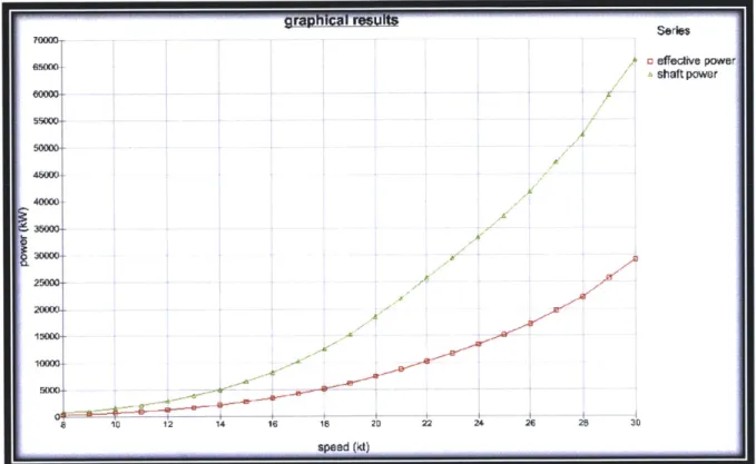
The maximum speed is, primarily, a component related to the installed power of the selected power plant. In determining the power required to perform per the specified maximum power, the ESSDT makes use of the Admiralty Coefficient, as expounded upon in greater detail in chapter 3. This, in turn, is used as part of the final graphical interface, as shown in Figure 13. It allows the user to visually ascertain if the selected power plant is capable of providing sufficient power to propel the vessel at the desired maximum speed.
The input parameter of "Range" is primarily used in ascertaining the ship's tankage requirements. In conjunction with the endurance speed, this input parameter is used to determine the designed vessel's tankage requirements. This, in turn, goes into the preliminary analysis of volume and weight requirements for tankage allowance for the design.
The selection for "Installed Power" provides the user with a drop down selection of available power plants produced from the output of an Integrated Power System Design Module (IPSDM) produced through research conducted in parallel to this thesis by David Jurkiewicz, a fellow 2012 Naval Engineer's degree candidate, in his thesis Modular Machinery
Arrangement and Its Impact in Early-Stage Naval Electric Ship Design (Jurkiewicz, 2012).
Beam and depth are driven by equipment and machinery selection. These are used in conjunction with the hull selected to determine initial length and draft of the ship. These values are then compared against default constraints. These constraints may force a design to have a different displacement than initially desired. To alert a user to this potential discrepancy, a "Final Displacement" read-out is provided. This displays the actual resulting displacement as currently determined by the program based on all present user input. The user also has the ability to manually alter the beam or length, but there is a warning provided against this action as it can have detrimental effects on the hull efficiency as compared to the parent hull the resulting ship model is based upon.
At this point in the process, the user may select whether or not to include aviation facilities in their design. If selected, the user may either have no hangar facilities, one hangar, or two hangars. If two hangars are selected, they may be oriented either fore-and-aft or
side-by-side. A helicopter type may also be selected at this time. Based upon this selection, the hangars will be sized accordingly. Placement and sizing of the flight deck is done along with equipment selection. Location and spacing between the hangars can be performed when constructing the deckhouse.
Since the development of IPS has not altered habitability requirements, "Crew Size" and "Endurance" are both used in a fairly traditional manner in conjunction with defaults and historically based parametric equations, to determine the volume and weight requirements which the number of personnel place on the design. Chapter 3 develops this in greater detail.
"Hull Type" allows the user to select a hull from a drop down menu consisting of hulls available in a "hull library". Each of the available hulls has control point information available which allows the program to construct a model of it within Paramarine which has been scaled in accordance with the needs of the designed vessel.
2.2.2 Initial Equipment Selection & Bulkhead Placement
Figure 14 illustrates the input table for equipment selection. The first column allows a drop-down selection of equipment type. Available choices are Gun, VLS, Sonar, Radar, and Misc (for miscellaneous, user defined equipment within the library).
Figure 14: Table for Initial Equipment Selection
location Vertical
type selection erical
&
FORE/AFT PORT/STBD Additional input Needed input (ft) AdJustment(%aft from FP) (% PORT from CL) (Vt)
MMR BoundingBoxes Master Madunery Bounding Box AtopjinnerBottom 40.00% 0.00% none
FihtDeck SH-60FSeahawk Weather.,Deck 90.00% 0.00% none -9
MUR BoundingBoxes OMR1 Atop inner Bottom 6.00% a10% none
MW Bounding_Boxes OMR2 Atopjinner Bottom 83.00% 0.00% none 9
MMR Bounding-oxes 0 WeatherDeck 7.00% 0.00% none
VtS Mk 41_64 rds strike Weather Deck 22.00% 0.00% none 11
VIS Mk 4 12 rds strike Weathe Deck 6400% 0% none 9
Gun 5 in_54 caliber Mark 45_pun Weather Deck 13.00% 0.00% Height-ofHoist 35 16
Gun Phalanx Mk 15 CiWS Weather Deck 26.0% .00% none 0 1i
Gun Phalanx Mk 5,CWs Weather Deck 80.00% 0.20% none 0 9
Sonar SOS 53C Bottom of Hull 2.00% 0.00% none
Radar SPY ID Weather Deck 3L00% 600% none 36
Radar SPYJD Weather Deck 3L0% -60.00% none 36
Radar SPY,1D Weather Deck 3.00% 60.00% none 27
Radar SPY I0 Weather Deck 3n00% -60 % none 27
&W0%
A0% RREFI
50.00% o0 EREF!
Once an equipment type is selected, a dropdown menu is then available in the next column for the equipment selection. This dropdown menu is populated by all equipment available in the program's library as further discussed in section 2.3 Equipment Library. The user can then place this equipment longitudinally, transversely, and vertically as a proportion of ship's length, a proportion of distance from ship's centerline, and vertical deck reference respectively. In the last column, a further vertical adjustment is allowed to vary location away from the limited number of reference decks available. Reference decks only include "BottomofHull", AtopInnerBottom", and 'WeatherDeck". This ability to adjust the
vertical reference allows all possible placements for any particular equipment item.
The first couple of rows within this input have fixed items. The first row is for placement of the main engine room module as provided by the IPSDM. It allows the user to move the Main Machinery Rooms (MMRs) and Auxiliary Machinery Rooms (AMRs) together within the ship the same way as any other equipment.
The next row allows placement of the flight deck if aviation facilities were selected. The flight deck is sized according to the helicopter selected based upon information stored within the equipment library. It is expected that the standard location for the flight deck will be the weather deck. However, if a vertical displacement of the flight deck is selected, when the ship is modeled within Paramarine, any hull structure located above and aft of the selected flight deck will be removed from the model. This is to allow modeling of stepped flight deck structures as certain ship classes have, DDG-51 flight IIA being a particular example.
The last three fixed rows are populated if the machinery plant selected has Other
Machinery Rooms (OMRs). These are machinery spaces which, due to function or
requirements, are not located in a fixed location with relation to the rest of the machinery spaces. These can also be moved around the ship as the user desires in the same way as any of the other equipment.
As each of these equipment items is selected and placed, a graphical representation is displayed in the upper right-hand corner of the display as shown in Figure 7.
2.2.3 Hanger & Deckhouse Construction
The tab "CreateDeckhouse" allows for the placement of hangar facilities and the construction of a ship's deckhouse as illustrated in Figure 8. Similar to other equipment components, the hangars are placed as a percentage of ship's length aft from the forward perpendicular. Transverse location is handled in a similar manner. Vertical location is referenced from one of the three aforementioned vertical references, "WeatherDeck", "AtopInnerBottom", and "BottomofHull". Just as with the other equipment components, a vertical displacement is also allowed for the hangars. This allows variation as can be seen in a
DDG-51 Flight IIA where the flight deck and hangar facilities are located one deck below the
weather deck with a "cut down" in the hull structure as discussed when dealing with the placement of the flight deck. It should be noted that the flight deck determines what portion of the hull is "cut-out" to allow for aviation operations.
Another input for the hangar facilities is whether or not to count them toward the deckhouse volume. This is an accounting device. If the hangar is considered within the deckhouse, then that volume is removed from the available volume for the deckhouse within the volume bank, as discussed in greater detail in section 3.2.3 Volume Bank.
As previously mentioned, the deckhouse is constructed as a selection of geometric modules consisting of rectangles and triangles. Originally, an interface allowing for control points defining up to eight sides for a module was attempted. This would have been similar to the deckhouse construction utilized in the ASSET version 6 and allowed much greater flexibility in deckhouse construction. However, given the methods Paramarine uses for defining the building blocks which make up the deckhouse, primarily cuboid in nature, this method proved untenably awkward. The simpler selection of only squares and triangles allows for the construction of, effectively, any geometry imaginable. At the same time this constrains the user to input this information in a manner in which Paramarine is able to easily handle it.
As mentioned, Paramarine primarily makes use of basic geometry, most notably cuboid structures, to define its construction geometry for ship models. The triangular structures were able to be modeled by constructing, within Paramarine, a cutting block of greater dimensions then the block being defined. This cutting block was then rotated in such a way that, by
subtracting its structure from the module being modeled, the module resulted in the desired
triangular shape.
For future iterations of this program, a similar technique could be used to model angled
deckhouse structures. A cutting block of sufficient dimensions could be constructed, rotated,
and used to subtract from the deckhouse block to create this angled structure. To facilitate this
future development, an input for angled sides has been provided within the deckhouse module
construction input. At this time, however, this input is not linked to any process; and inputting
any information into this file will have no effect on the modeled ship within Paramarine.
As these deckhouse modules are constructed, they are visualized in the image in the
upper left of the input page shown in Figure 8. An example can be seen modeled as the black
structures within Figure 15. As with all other inputs, though, these modules are not visible
within the image depicted in Figure 15 until the Excel file has been updated by one of the
previously mentioned methods.
4-0 40
1
10100350
Figure 15: Deckhouse Figure Output
2.3 Equipment Library
The equipment library contains all pre-populated equipment which may be inserted into
the design. It is constructed in such a way that more equipment may be included within the
library at a future date. This library is referenced by the ESSDT for initial equipment which the
user has the option of including with the design, construction of diagrams within Excel, and eventual export into Paramarine. As part of the export process into Paramarine, an equipment library is populated within the Paramarine model with all selected items. This allows a user to further develop the model within Paramarine after initial import. At this time, only the items selected for initial inclusion in the model are imported into Paramarine. However, a future macro within the Excel model could be developed to allow for expanded populating of the equipment library in Paramarine to further facilitate model development once the design process has moved from ESSDT to Paramarine.
There is also a library for hull forms which will be discussed in greater detail in section
3.3 Hull Creation.
2.3.1 Library Components
Equipment stored within the equipment library is categorized as either a gun, Vertical Launch System (VLS), radar, sonar, hangar, flight deck, or miscellaneous. Table 1 and Table 2 contain an abbreviated list of some of the equipment initially included in the ESSDT's library for preliminary testing.
Table 1: Equipment within Library
Gun VLS Radar
5_ir 54 c afber Mark_45_gun' Mk41 8 ds- strike AN/PS 49(V)1, PhalanxMk_15_CIWS Mk_41_64_rdsstrike AN/SPS_49(V)2_(V)1
AN/SPS_49(V)8 ANX_(V)8
Table 2: Equipment within Library (cont.)
Sonar
Hanger & Flight Deck
Misc
Firescouts
MH-60SSeahawk
CH-53ESuperStallion
Although there are, currently, no items within the miscellaneous category, it is included
for expansion to include future systems which do not easily fall under any of the other
categories.
2.3.2 Information Contained Within the Library
Each item contained within the library has entries for all pertinent data for preliminary
modeling. For the gun, radar, sonar, and VLS systems, these include the weight with relative
centroid, power, clearance box, file locations for graphics, number of people required for
operation and maintenance, cooling requirements, electrical requirements, and an option for
additional input. The flight deck and hangars include only geometric requirements since the
weight of structure would be accounted for in the ship's estimate of Ship's Work Breakdown
Structure (SWBS) group 1. However, they do include the ability to enter an additional weight
should the requirements for support of a particular type of helicopter require some additional
structure such as a reinforced flight deck for a heavy air frame.
For the weight of each item, the library can accommodate up to four different weights
with their respective centroids. These can be flexibly used to model the equipment item as
deemed best by the user. For example, with a gun, one weight might be used for the gun and
mount itself, one to model the hoist system, and one to model the magazine. It is up to the
user to decide how to split up the item's weight. The centroids are referenced to a control
point which is the point the user places when selecting and placing equipment. For example, a
logical control point for a VLS system would be at the center, top of the system where it would be located on the weather deck. If the center of mass for this item is 15 feet below the top of the VLS, the weight's centroid should be entered as -15 ft. Then, when exported to Paramarine, the ESSDT will place the center of mass for the item 15 feet below wherever the user specified the equipment to be placed.
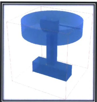
Similar to weight, the library can also store up to four clearance boxes and graphics locations. The clearance boxes are meant to represent the area of and around the equipment item which must be dedicated to that system. Just like the weights, they are spatially referenced to the control point. They may be constructed of cuboids, cylinders, or spheres. The graphics are parasolid object files placed within the graphics folder in the ESSDT program. They must consist of a single solid body. When imported into Paramarine, both the clearance
box and graphic are imported into Paramarine's equipment library as shown in Figure 16.
In Figure 16, the upper cylinder is a clearance box representing the sweep of the gun, the bottom cuboid is a clearance box representing the magazine, and the connecting cuboid is a clearance box representing the hoist system.
However, if there is a graphic for a particular piece of equipment, only the graphic is displayed in the actual ship model. If there is no graphic, the clearance box takes the place of the graphic. This can be seen in Figure 17 where the clearance boxes for the magazine and hoist are displayed since there is no graphic to replace them, but the clearance box representing the sweep of the gun is removed in favor of the graphic designated to replace it.
Figure 17: Model of 5" Deck Gun in Paramarine Model
Each of the equipment items also has the ability to enter the number of crew members that an item would require for operation, upkeep, and maintenance. Effectively, it is meant to represent the increase in crew size required by including that particular equipment item. Currently, this entry has no effect on the model. It has been included so that future iterations of the ESSDT might be able to project necessary crew compliments based upon equipment selected rather than just having crew size as a user input.
I
I -
--Now
The cooling requirements have several potential inputs. The equipment can have cooling loads for shore, design, cruise, and battle operational conditions. There is also the ability to specify the relative x, y, and z location of the cooling connection; Header (HDR) connection type (starboard, port, both, or cross connect); and, for the cross-connect situation,
how the cross-connect is oriented.
The cooling requirements are imported into Paramarine as service demands under the characteristics of the equipment within the equipment library. As such, they are listed as a demand, what type of cooling they require (currently only chill water), and what maximum energy removal they require. The additional information within the library has been included in a format similar to that required by a similar, previously developed Cooling System Design Tool
(CSDT) (Fiedel, 2011). Hopefully, the inclusion of this data for the equipment in this format will
allow for eventual incorporation of the CSDT into the ESSDT.
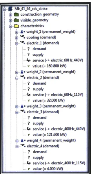
Similar to weight, clearance boxes, and graphics, electrical requirements of the equipment also have four potential loads listed within the database as shown in Figure 18.
e ectric power requiren-ents
electrical req. A1 electrical req. #2 eledrical req. #3 electrical req. 84
frepowerltw) (k-) owe powerlkw) power (kw)
ME feq oltae freq olt~ef reftlt8req voltagestn e Ipa
11
Sy~stem standy ronal k & -eu TPksalb ot 0 prationalT;; npetnd by rat'oa eMk,41 :8rdstrke 60 440 38.4 14.1 20.1 60 115 64 10.4 4 400 440 0 12 15.2 400 115 0 (.5 0.5
Mk 41 64 rdsstrke 60 440 307.2 1128 161 60 115 51.2 83.2 32 400 440 0 96 122 400 115 0 4 4 Mk,41 128 rds strike1 60 440 614A 225.6 322 60 115 1024 166A 64 400 440 192 243 400 115 0 8 a
Figure 18: Electrical Requirements within Equipment Library
The library provides for a drop down selection of available frequencies (or DC) as well as required voltage and standby, operational, and peak powers. Although not currently utilized, the library also allows the specification of x. y, and z locations for each of these required services. This can potentially allow for the future development of service highways within the Paramarine model. The highlighted information from Figure 18 translates into Paramarine's equipment library as shown in Figure 19.