HAL Id: hal-02448795
https://hal.archives-ouvertes.fr/hal-02448795v2
Submitted on 3 Jul 2020
HAL is a multi-disciplinary open access
archive for the deposit and dissemination of
sci-entific research documents, whether they are
pub-lished or not. The documents may come from
teaching and research institutions in France or
abroad, or from public or private research centers.
L’archive ouverte pluridisciplinaire HAL, est
destinée au dépôt et à la diffusion de documents
scientifiques de niveau recherche, publiés ou non,
émanant des établissements d’enseignement et de
recherche français ou étrangers, des laboratoires
publics ou privés.
Vehicle platooning schemes considering V2V
communications: A joint communication/control
approach
Tiago Rocha Gonçalves, Vineeth Varma, Salah Elayoubi
To cite this version:
Tiago Rocha Gonçalves, Vineeth Varma, Salah Elayoubi.
Vehicle platooning schemes
consid-ering V2V communications: A joint communication/control approach.
IEEE Wireless
Commu-nications and Networking Conference, WCNC 2020, May 2020, Seoul, South Korea.
pp.1-6,
Tiago R. Gonc¸alves
1, Vineeth S. Varma
2, and Salah E. Elayoubi
1Abstract—This article addresses communication and control aspects of platooning systems with the related challenges intro-duced by the overlap of both areas. The main objective is to provide a dynamic control mechanism where the parameters of the well-known Predicted Cooperative Adaptive Cruise Control (PCACC) are adapted based on the observed quality of the V2V (Vehicle-to-Vehicle) communication links. Different from the state of the art, our main design goal is the minimization of inter-vehicular distances while being robust in terms of an extremely low probability of emergency braking. A new adaptive control scheme based on the offline optimization of the control gains is proposed. We evaluate the new approach in a highway scenario and show the improvements obtained by the dynamic adaptation of the control parameters over static control strategies.
Index Terms—Vehicle platoons, cooperative adaptive cruise control (CACC), wireless communication.
I. INTRODUCTION
During the last decades, several approaches have been developed to deal with autonomous vehicles. Among some of the control technologies that were deployed to help the drivers’ safety and increase their driving experience, one can cite the Cruise Control (CC) as a precursor of autonomous cars. However, the first meaningful step to allow the implementation of platoons in the vehicular environment was the establishment of the Adaptive Cruise Control (ACC). It was first introduced by Ioannou and Chien [1] and it consists of an autonomous control scheme based on constant time headway safety dis-tance. Essentially, it allows autonomously to keep a certain desired distance from the preceding vehicle due to onboard sensors such as camera, radar, and lidar. A more sophisticated approach based on a coordinated exchange of information supported by wireless communication was early provided by Rajamani et al. [2] and it is known as Cooperative Adaptive Cruise Control (CACC). However, as CACC technology relies on other’s vehicle information it is vulnerable to inherent communication aspects such as packet loss and latency. Our particular interest in the platooning system is because it is designed to take advantage of the particular distribution of a convoy in order to increase road capacity and to decreased fuel consumption that is achievable by gathering vehicles close together in order to reduce the air resistance of the
1 T. R. Gonc¸alves, and S. E. Elayoubi are with Universit´e
Paris-Saclay, CNRS, CentraleSup´elec, Laboratoire des signaux et syst`emes, 91190, Gif-sur-Yvette, France. E-mail: {tiago.rochagoncalves; salahed-dine.elayoubi}@centralesupelec.fr.
2 V. S. Varma is with Universit´e de Lorraine, CRAN, CNRS, UMR 7039,
France. E-mail: [email protected].
platoon’s members. The exchange of information is crucial to the deployment of platoons as it allows taking control actions based on the most up-to-date information about the road and traffic status.
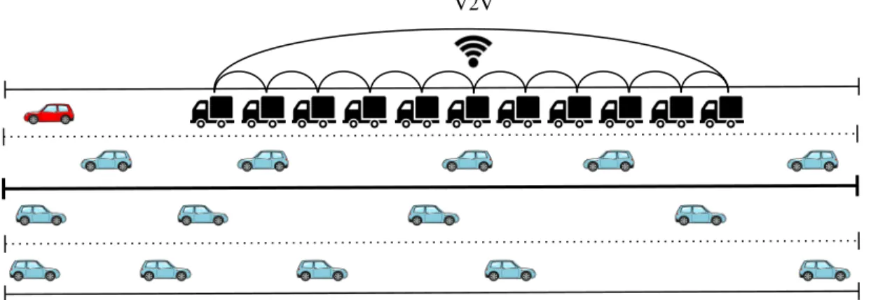
We consider in this paper the V2V communication method in platoons as illustrated in Fig. 1. V2V enables communica-tion between vehicles as long as they are in a certain range. This is the case of the IEEE 802.11p and 3GPP C-V2X Mode 4 technologies. The former is an adapted version of the IEEE 802.11a to suit vehicular applications [3], while the latter is the direct communication interface standardized by the 3GPP. Notice that the network-based communication approach of the 3GPP standard, known as 3GPP C-V2X Mode 3, is not considered here. [4] conducted simulations to show a compre-hensive analysis of the advantages of the performance of C-V2X Mode 4 over the 802.11p. Similarly, [5] used a simulation environment to compare the communications performance of both modes 3 and 4 of C-V2X with the 802.11p standards. More recently, [6] adopted an analytic approach to describe the C-V2X Mode 4 performance. However, these works were limited to the telecommunication aspects and did not consider the control aspects of the platooning problem.
Another set of works considered the platooning scenario under different communication approaches. For instance, [7] used the 802.11p technology to evaluate the communication performance under a CACC controller in platoons. Likewise, [8] has adopted both wireless technologies (802.11p and C-V2X) and compared their performances in terms of the inter-vehicular distance of the platoon. [9] proposed a control strategy for graceful degradation based on estimating the preceding vehicle’s acceleration in case of packet losses, but it mainly deals with extreme cases like complete link failure or lack of a wireless device on one of the vehicles. Different from the aforementioned article, we propose an online adaptation of the control parameter based on the observed quality of the communication link determined by the distance to the trans-mitter and the level of interference caused by other vehicles. More recently, [10] introduced a string stability analysis for a CACC alternative control design, in this paper called Predicted Cooperative Adaptive Cruise Control (PCACC).
The novelty in this paper is the introduction of a dynamic control mechanism where some of the parameters of the PCACC controller are adapted based on information about V2V communication. In particular, we adapt the parameter that is responsible to weigh the influence of the leader’s
V2V
Fig. 1. Traffic scenario including a platoon with V2V communication approach.
broadcasted messages in the control algorithm, as well as the target distance between vehicles, based on the communication links qualities. Keeping in mind the above discussion and the results available in the literature on cooperative platooning systems, the following are the main contributions of this paper: 1) Evaluation of the robustness of the platooning mecha-nism under severe conditions for V2V communications, expressed in long bursts of losses and in difficult traffic jamming conditions on the road.
2) Offline optimization of the platooning control parame-ters based on extensive simulations of a highway sce-nario.
3) Online adaptation of the control parameters based on the observed communication link quality and on the results of the offline optimization.
4) Adoption of safety as a primary performance metric, quantified in terms of avoiding emergency braking. This translates to robustness constraints, where the inter-vehicle distance in the platoon is set so that emergency braking is avoided in 99,999% of the cases.
The paper is organized as follows. An overview of the control and communication aspects is presented in Section II, and the proposed scheme is described. Section III presents the system model, introduces the robustness case scenario and discusses the performance evaluation. Section IV includes considerations for future work and concludes the paper.
II. CONTROL ANDCOMMUNICATIONPLATOONING
SCENARIOS
The objective of this section is to present the control schemes and their interaction with algorithms performance, and to introduce the proposed scheme based on PCACC. A. Adaptive Cruise Control
The ACC scheme autonomously allows the equipped vehicle to keep a certain desired distance apart from the preceding vehicle. This is possible because of the adoption of cameras, radars, and lidars that measure in real-time the preceding vehicle’s position and velocity. Different spacing policies can
TABLE I
COMMUNICATION ANDCONTROLLERPARAMETERS
Communication Controller
Parameter Value Parameter Value
Channel Highway NLOS Leader factor (C1) Adaptive
Path loss Winner+B1 LOS Desired distance (Ddes) Adaptive
Noise power -174 dBm/Hz Damping ratio (ξ) 2
Tx power 22.5 dBm Bandwidth (ωn) 0.5 Hz
MCS QPSK, R=1/2 Time gap (h) 1.4 s
CAM size 500 bytes Vehicle length (L) 16.5 m
CAM interval 100 ms Actuator lag (τ ) 500 ms
Radar interval 60 ms Lane width 5 m
Process delay 1 ms
be used such as Constant Spacing (CS) and Constant Time-Gap (CTG) policy, for instance, see [11]. Briefly, the controller on the former scheme aims to keep a constant distance of the preceding vehicle while on the latter one it aims to control the clearance, or time gap, between the host vehicle and the preceding vehicle. In this paper, the CTG policy is applied with the following control law introduced by Ioannou and Chien [1]
ai des= ¨xi des= − 1 h( ˙εi+ λδi) (1) where εi= xi− xi−1+ Li−1 (2) δi= εi+ h ˙xi (3)
are the inter-vehicle spacing and the spacing error, respec-tively. The index i symbolizes the vehicle index, the first vehicle being numbered 0. xi denotes the position of vehicle
i, Li its length and ai its acceleration. h is the time-gap
parameter andλ is the design gain parameter. The control input is calculated based on the difference of its own velocity and position with the preceding vehicle, (˙xi,xi) and (˙xi−1, xi−1)
respectively. Note that in platooning systems, the ACC control law is always adopted by the leader since it is preceded by a vehicle that is not subject to the platooning controller. B. Predictive Cooperative Adaptive Cruise Control
PCACC, introduced in [10], implies that the control effort, the desired acceleration, of the leader and of the preceding
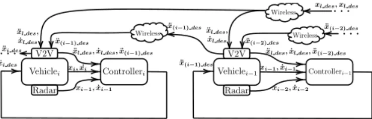
Fig. 2. Block diagram of the platoon system with a PCACC control between vehicle i− 1 and vehicle i.
vehicle are available to the following vehicle and its control law is given by
ai des= ¨xi des= (1 − C1)¨x(i−1) des+ C1x¨l des
− (2ξ − C1(ξ +pξ2− 1))ωn˙ǫi − (ξ +pξ2− 1)ω nC1( ˙xi− ˙xl) − ω2nǫi (4) where ǫi=xi− xi−1+ Li+ Ddes (5) ˙ ǫi= ˙xi− ˙xi−1. (6)
Li is the length of the vehicle and Ddes is the desired
inter-vehicular distance that we want to minimize. The control parameters to be tuned are C1,ξ and ωn. The parameter C1
takes on values 0 ≤ C1 < 1 and is responsible to weigh the
contribution of the leader’s speed and acceleration. ξ is the controller damping ratio and ωn is the controller bandwidth.
The adopted control parameters are shown in Table I. Such improvement of this fully predictive cooperative control is due to the fact that it allows the communication between all the vehicles in the platoon including the leader as shown in Fig. 2. It also illustrates the input signals required by the PCACC controller and the respective segments (V2V radio, vehicle dynamics, and radar equipment) that provide them. In other words, the CACC sends the actual acceleration, which is measured after the actuation lag, while the PCACC is able to propagate the actual values that will become effective after the actuation lag. The PCACC is expected to be superior to CACC because the actuation lag of the system does not affect directly the control effort, which is a big limiting factor for achieving short inter-vehicle distances [8].
C. Semi-Autonomous Control
This is a particular class of control that allows the system to achieve string stability with a constant space control strategy without direct communication from the leading vehicle. The control strategy can be obtained with a simple change in one of the control parameters of the CACC control scheme. Therefore,C1= 0 yields
ai des= ¨xi des= ¨xi−1− 2ξωn˙ǫi− ω2nǫi. (7)
The control law is based on one vehicle look-ahead commu-nication topology, which means that only preceding vehicle’s information is required. In this case, its acceleration, velocity,
the first vehicle is not going to cause an amplification of the error along the tail of the platoon. In other words, as long as the first vehicle is able to avoid a collision all others will be able too. In [11], there is more information about mathematical definitions and conditions to ensure the string stability. D. Proposed dynamic scheme based on PCACC
In contrast to existing works that assume a fixed control strategy, our main contribution is to propose an approach that will adapt the control parameters based on the communication link quality characterized by the packet error rate from the leader to the last vehicle (defined as PERLLV). We aim to
keep a homogeneous control strategy in the whole platoon. In particular, among the control inputs, the pair (C1, Ddes)
has the most substantial impact on the performance of the system. As mentioned before,C1 is responsible to weigh the
influence of the leader’s message in the control algorithm whileDdesis the desired inter-vehicular distance that we want
to set, but due to actuator lag and delay in the process it does not correspond to the actual average inter-vehicular distance (Davg). The following algorithm based on PCACC controller
is proposed.
• Step 1: Update the traffic density range limits (PERLLV). • Step 2: Vary theC1 parameter while minimizingDdes
and register the average inter-vehicular distanceDavgfor
each PERLLV inside the range of Step 1.
• Step 3: Consider the minimum Davg result with
no collision and identify its correspondent pair of (C1(P ERLLV), Ddes(P ERLLV)) to build the optimum
lookup table(C∗
1(P ERLLV), D∗des(P ERLLV)). • Step 4: Observe the current communication link and
adapt the control inputs(C1, Ddes) accordingly based on
the optimum lookup table of Step 3.
Therefore, we conduct an offline heuristic optimization to determine the best control parameters (C1, Ddes), in terms
on minimum inter-vehicular distance without collisions, for any given value of PERLLV (which is the result of the
traffic density and the resulting interference). We build a (C∗
1(P ERLLV), Ddes∗ (P ERLLV)) lookup table that will
serve as an optimum reference for each PERLLV value.
Many existing works on CACC and PCACC mention the minimum distance possible assuming a certain level of inter-ference or traffic on parallel lanes, however, it is not clear what should be done in practice where these parameters will evolve over time in an unknown manner. We propose to apply an online adaptation of the parameters(C1, Ddes) based on the
observed PERLLVand on the results of the offline optimization.
Note that due to actuator lag and delay the string stability is not guaranteed for all platoon sizes other than those evaluated.
0 30 60 90 Time (s) 8 10 12 14 16 18 20 22 24 Velocity (m/s) } (34.25,9.72) (64.25,9.72) (60,22.22) (30,22.22) (90,22.22) burst
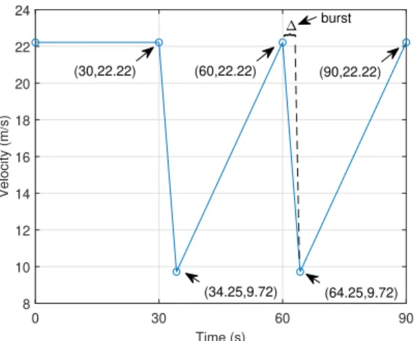
Fig. 3. Illustration of the jammer velocity profile adopted with 2 cycles.
III. SIMULATIONASSUMPTIONS ANDPLATOONMODEL
In this section, we present the system model, the control and communication parameters, and the simulation tool adopted. A. Vehicle dynamics
The vehicle dynamics is modeled as first-order low pass filter due to the actuator lag. So the transfer function is modeled in the frequency-domain as
G(s) = Ai(s) Ai des(s)
= 1
τ s + 1 (8) whereτ is the time constant of the first-order low pass filter. Aiis the output, which can be interpreted as the actual vehicle
acceleration, whereas Ai des is the vehicle input, which can
be seen as the desired acceleration. Note that,·(s) denotes the Laplace transform of the corresponding time-domain variable. The idea is to approximate the dynamics of the throttle body and vehicle inertia in order to avoid instantaneous response. In this paper, we assumed a lag of τ = 0.5 s as in [11]. B. Platoon Scenario and Robustness Criterion
The system consists of a platoon of 10 automated vehicles following the leader. The simulated scenario takes place in a four-lane highway, as illustrated in Fig. 1, with a maximum traffic density of 20 interfering vehicles/km. The vehicles of all other lanes are not in platoons (blue vehicles) and a jammer (in red) precedes the platoon leader. In the offline optimization section, the speed of the jammer (vehicle outside of the platoon) follows a preset sequence, adapted to only two cycles from [8], as shown in Fig. 3. The main reason for this jammer velocity profile is to study the capacity of the platoon system to avoid a collision in risky scenarios such as when the vehicle outside of the convoy suddenly applies the maximum brake capacity. Furthermore, different from the previous articles so far that just do Monte-Carlo simulations (100 or 1000 iterations of normal conditions), we have considered a burst of packet losses. While bursts are rare events, they may occur and impact the safety of the platoon,
but are not well reflected in the numerical analysis of most previous works like [7]-[13]. In this sense, the robustness treated here is related to the following worst-case event: the jammer brakes at some time (t = 60 s in our simulation) and this braking coincides with a burst of packet losses (complete interruption of the transmitted signal) during the following intervalt + ∆ also illustrated in Fig. 3.
In order to be conservative, we consider long bursts of packet losses that occur with a probability of10−5. Denoting
by PER the probability of packet loss taking into account the channel model and packet collisions andT the time sampling interval for vehicle information, the burst size∆ (in seconds) can be calculated as
∆ = −5/(log10PER)T (9)
In our simulations, we have considered the sampling rate of T = 100 ms as advocated by the ETSI EN 302 637-2 standard. C. Simulation tool
We used the MATLAB/Simulink environment to model the vehicle dynamics and to implement the control law. Further-more, we adopted the WLAN Toolbox of MATLAB to im-plement the channel configuration for a 802.11p transmission in order to obtain the Packet Error Rate (PER) taking into account the V2V fading channel aspects, the additive white Gaussian noise, the packet collisions and others communica-tion parameters as in Table I. The mobility behavior of vehicles is also observed in the MATLAB/Simulink environment as we consider a traffic scenario as in Fig. 1. So at the begin-ning of each simulation step, from the “Radar” module the “Controlleri” is able to update the velocity and the position
of the preceding vehicle ( ˙xi−1, xi−1) as in Fig. 2. Also, the
block “Vehiclei” provides the vehicle’s dynamics, thus its own
velocity and position ( ˙xi, xi), to the “Controlleri” module.
Furthermore, the controller reads the leader’s acceleration and velocity and the preceding vehicle acceleration (¨xl, ˙xl, ¨xi−1)
from the “V2V” module. Recall that in the leader vehicle we implement an ACC controller, so the “V2V” module is responsible only to broadcast its acceleration and velocity since the ACC controller does not require any other inputs as those provided by the modules “Radar” and “Vehicle”. Based on the inputs mentioned, the “Controlleri” module is able to
calculate the desired acceleration (¨xi des) in order to keep a
certain desired distance (Ddes) from the preceding vehicle.
Thus, the “Vehiclei” module, responsible to approximate the
dynamics of the vehicle, applies the desired acceleration and provides as output the vehicle’s position and velocity at the next simulation step.
The WLAN Toolbox is used to simulate the wireless con-dition for a 802.11p transmission. We adopted two different packet error rate parameters. The first one is related to the packet error rate between two successive vehicles and defined as PERi,i+1 along the article. We adopted an Highway
line-of-sight (LOS) profile as vehicles in the platoon are close enough to justify the usage. The second one is the packet error rate between the leader to the last vehicle that was defined as
IV. PERFORMANCEEVALUATION
The leader is equipped with an ACC control to be in accordance with the recommended safety time interval gap of the respective local law while the platoon is equipped with fully predictive cooperative control. The focus is to apply a longitudinal control in the platoon through V2V communication technology and analyze the system stability by means of vehicle collisions in some robust and worst-case scenarios. We considered the zero-order hold mechanism as the holding strategy for the control signal during the periods of packet losses. Furthermore, in all simulations, we focus on obtaining the minimum feasible inter-vehicular distance in the platoon with a emergency breaking probability no more than10−5. Note that we implemented a safety gap distance of
0.5 m for the emergency braking actuation to avoid collisions in practical settings.
The control strategy demands relative position and lon-gitudinal velocity of the preceding vehicle so we assumed that the measurements are sampled each 60 ms with 1 ms process delay and done by a long-range radar as in [8]. All the vehicles in the platoon broadcast a 500 bytes message on a 10 MHz channel bandwidth. Neighbouring vehicles are subject to a Highway LOS channel model [15] and our simulations provide a PERi,i+1∈ {0.006, 0.0245} for the cases
without interference and with interference, respectively. We have adopted PERi,i+1= 0.0245 as the default value. As of the
leader communication, the leader broadcasts a message to all other vehicles that is subject to a Highway NLOS channel [15] with PERLLV∈ {0.2, . . . , 0.7}, depending on the interference
conditions.
A. Offline optimization
We start by performing an offline optimization of the control parameters(C1, Ddes). Fig. 4 illustrates the substantial impact
ofC1parameter on the average inter-vehicular distance (Davg)
for different PERLLVvalues. Thus, from Fig. 4 we can retrieve
the C∗
1 optimum that minimizes the inter-vehicular distance
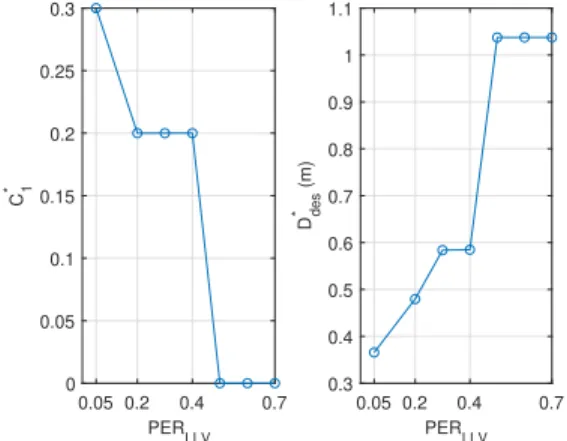
for each PERLLV evaluated, which is illustrated in Fig. 5 on
the left. Similarly, the optimumDdes values were established
as shown in Fig. 5 on the right. In this figure, C1 = 0.3
represents the best alternative in the robust scenario for low PERLLVvalues. While,C1= 0.2 indicates to be the best value
for mid-range values as 0.2 ≤ PERLLV ≤ 0.4. For higher
PERLLV ≥ 0.5 the best parameter values is C1 = 0 which is
the case of semi-autonomous control.
B. Online adaptation of the control parameters
We now move to the online adaptation of the control parameters, where the whole platoon adapts the control inputs
0 0.05 0.1 0.15 0.2 0.25 0.3 0.35 0.4 C 1 1 1.5 2
Fig. 4. Illustration of the average inter-vehicular distance with PERi,i+1=
0.0245for different C1values.
0.05 0.2 0.4 0.7 PERLLV 0 0.05 0.1 0.15 0.2 0.25 0.3 C1 * 0.05 0.2 0.4 0.7 PERLLV 0.3 0.4 0.5 0.6 0.7 0.8 0.9 1 1.1 Ddes * (m)
Fig. 5. Illustration of the optimum C1 and Ddes parameters for different
PERLLVvalues.
(C1, Ddes) corresponding to the optimal values computed in
the offline optimization based on the packet loss observed on the communication link by the leader and the last vehicle (PERLLV). For comparison purposes, we also simulated cases
with fixed control parameters. The idea is to inspect the occurrence of collisions and to compare the inter-vehicular distance of the platoon in a long simulation of 25 minutes in three different cases defined as follows:
• Case 1 - PCACC with fixed C1 = 0.2. In this case, we
apply the Ddes correspondent to the average PERLLV.
We aim to treat the case where the system operates in a moderate scenario where it’s not too conservative.
• Case 2 - Semi-autonomous (C1 = 0). In order to have
a robust controller, we apply the Ddes corresponding to
the worst-case PERLLV.
• Case 3 - The proposed dynamic scheme where the control
parameters are based on the observed PERLLV.
In all cases, we considered the jammer profile as the pattern from Fig. 3 repeated 50 times. Another important factor is the traffic density that generates interference and changes the PER. In order to have a fair comparison between all cases, we apply a predefined traffic density in the simulation. The range of the traffic densities varies from 0 vehicle/km to 20 vehicle/km
TABLE II
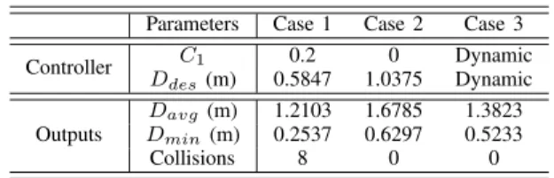
CASE COMPARISON FOR THE ONLINE IMPLEMENTATION. Parameters Case 1 Case 2 Case 3
Controller C1 0.2 0 Dynamic Ddes(m) 0.5847 1.0375 Dynamic Outputs Davg(m) 1.2103 1.6785 1.3823 Dmin(m) 0.2537 0.6297 0.5233 Collisions 8 0 0
that corresponds to PERLLV = 0.2 and PERLLV = 0.7 for
a 11 platoon vehicle in the considered scenario, respectively. The predefined traffic densities starts from PERLLV= 0.2 and
during each 2 minutes (4 cycles) it adds0.1 in the PERLLVup
to the maximum PERLLV= 0.7. Then, with the same logic, it
decreases to the minimum PERLLV = 0.2 and then increases
again until PERLLV = 0.4 where its elapsed time reaches 25
min. Notice that the traffic density changes linearly and less frequently than the jammer incidents. We applied the burst as in (9) in each 6 min of simulation in the 9th vehicle in
the platoon to simulate the burst of packet losses in the most critical moment.
From Table II, we notice that Case 1 exhibited 8 collisions while cases 2 and 3 had none. The former case comprises the event where the system is assumed to operate in an average traffic condition such as PERLLV = 0.4. However, it can be
seen that this is not a safe approach since it does not guarantee a secure outcome. Case 2 corresponds to the case where the optimum (C∗
1, D∗des) control parameters are set for higher
PERLLV values (worst case). Note that this corresponds to the
adoption of the semi-autonomous control asC1= 0. The idea
behind this scenario is to have a robust and safe outcome. Despite no collisions, it exhibited an increase of 21% in the inter-vehicular distance when compared to the suggested Case 3 approach. Fig. 6 shows the average inter-vehicular distance and the correspondent PERLLVvalue of the suggested approach
for the considered simulation. Therefore, the proposed method is demonstrated to be the best option so that platoon remains safe and robust while reducing the inter-vehicular distance.
V. CONCLUDINGREMARKS
This paper studies the design of the platoon control algo-rithm based on the V2V communication quality. We started by devising the optimal parameters of the controller for different communication qualities, namely the weight given to the infor-mation broadcast by the platoon leader (C1parameter), and the
desired distance (Ddes) between vehicles. We then proposed
a new dynamic approach based on the offline optimization of the control parameters(C1, Ddes). In this dynamic scheme, the
quality of the communication link is continuously monitored and the control parameters updated accordingly based on the results of the offline optimization. Our simulation results show that, if the control parameters are not adapted to the channel quality, the semi-autonomous control performs best. However, with the proposed adaptive control, using leader information results in a better performance. In future work, combin-ing different wireless technologies, such as V2N (Vehicle-to-Network) and VLC (Visible Light Communication), is a
Fig. 6. Illustration of the average inter-vehicular distance of the Case 3 simulation and the correspondent boundaries of PERLLV.
promising means for enhancing the robustness of the platoon while reducing the inter-vehicle distance.
REFERENCES
[1] P. A. Ioannou, and C. C. Chien, “Autonomous intelligent cruise control,” IEEE Tran. on Vehicular technology, vol. 42, no. 4, 1993, pp. 657-672. [2] R. Rajamani, et al. “Design and experimental implementation of longi-tudinal control for a platoon of automated vehicles,” Journal of dynamic systems, measurement, and control, vol. 122, no. 3, 2000, pp. 470-476. [3] D. Jiang, and L. Delgrossi, “IEEE 802.11p: Towards an international standard for wireless access in vehicular environments”, IEEE Vehicular Technology Conference, VTC Spring, 2008.
[4] R. Molina-Masegosa, and J. Gozalvez, “LTE-V for sidelink 5G V2X vehicular communications,” IEEE Vehicular Technology Magazine, vol. 12, no. 4, 2017, pp. 30-39.
[5] M. Wang, et al., “Comparison of LTE and DSRC-based connectivity for intelligent transportation systems,” Proc. IEEE 85th Vehicular Technol-ogy Conference(VTC Spring), 2017.
[6] M. Gonzalez-Mart´ın, M. Sepulcre, R. Molina-Mesegosa, and J. Goza-lvez, “Analytical Models of the Performance of C-V2X Mode 4 Vehic-ular Communications,” IEEE Trans. on VehicVehic-ular Technology vol. 68, no. 2, 2019, pp. 1155-1166.
[7] A. Vinel, L. Lan, and N. Lyamin, “Vehicle-to-vehicle communication in C-ACC/platooning scenarios,” IEEE Communications Magazine, vol. 53, no. 8, 2015, pp. 192-197.
[8] V. Vukadinovic, et al., “3GPP C-V2X and IEEE 802.11 p for Vehicle-to-Vehicle communications in highway platooning scenarios,” Ad Hoc Networks, vol. 74, 2018, pp. 17-29.
[9] J. Ploeg, E. Semsar-Kazerooni, G. Lijster, N. van de Wouw, and H. Nijmeijer, “Graceful degradation of cooperative adaptive cruise control.” IEEE Transactions on Intelligent Transportation Systems, vol. 16, no. 1, 2015, pp. 488-497.
[10] M. Sybis, et al., “Communication Aspects of a Modified Cooperative Adaptive Cruise Control Algorithm”, IEEE Transactions on Intelligent Transportation Systems, 2019.
[11] R. Rajamani. Vehicle dynamics and control, Springer Science & Busi-ness Media, 2011.
[12] D. Swaroop, and J. K. Hedrick, “Constant spacing strategies for pla-tooning in automated highway systems,” Journal of dynamic systems, measurement, and control, vol. 121, no. 3, 1999, pp. 462-470. [13] G. Cecchini, A. Bazzi, B. M. Masini, and A. Zanella, “Performance
com-parison between IEEE 802.11 p and LTE-V2V in-coverage and out-of-coverage for cooperative awareness,” Proc. IEEE Vehicular Networking Conference(VNC), 2017, pp. 109-114.
[14] IST-4-027756, WINNER II, “D1.1.2 V1.2, WINNER II channel mod-els,” Tech. Rep. v1.2, 2008.
[15] P. Alexander, D. Haley, and A. Grant, “Cooperative intelligent transport systems: 5.9-GHz field trials,” Proc. of the IEEE, vol. 99, no. 7, 2011, pp. 1213-1235.