HAL Id: inria-00537316
https://hal.inria.fr/inria-00537316
Submitted on 18 Nov 2010
HAL is a multi-disciplinary open access
archive for the deposit and dissemination of sci-entific research documents, whether they are pub-lished or not. The documents may come from
L’archive ouverte pluridisciplinaire HAL, est destinée au dépôt et à la diffusion de documents scientifiques de niveau recherche, publiés ou non, émanant des établissements d’enseignement et de
Wing shape optimization using FFD and twist
parameterization
D. Chauhan, Praveen Chandrashekarappa, Régis Duvigneau
To cite this version:
D. Chauhan, Praveen Chandrashekarappa, Régis Duvigneau. Wing shape optimization using FFD and twist parameterization. 12th Aerospace Society of India CFD Symposium, Aug 2010, Bangalore, India. �inria-00537316�
D. Chauhan, Praveen. C
TIFR Center for Applicable Mathematics, Bangalore, India Email: (dchauhan,praveen)@math.tifrbng.res.in
and
R. Duvigneau
Project OPALE, INRIA Sophia Antipolis, France Email: [email protected]
Optimization of wing shapes for aerodynamic performance is presented using a combination of particle swarm method and surrogate models. The wing shape de-formations are parameterized using free form deformation together with wing twist. The developed strategy is applied to the lift-constrained drag minimization of Onera M6 wing.
Keywords: Particle Swarm Optimization, Free Form Deformation, Wing twist pa-rameterization, Surrogate Models, Shape optimization
1 Introduction
Numerical shape optimization for aerodynamic problems can lead to improved designs than what is possible by conventional methods. Gradient-based optimization methods require the development of adjoint codes which can be a lengthy exercise and is also not very mature for RANS-based approaches. Furthermore, they may lead to locally optimal solution only, which is not desirable, especially in a preliminary design stage. Gradient-free methods are in this sense attractive and they also have the potential to give globally optimal solutions. The use of Euler/RANS codes for modeling the flow in a design context can be computationally expensive due to the need to evaluate many designs. However, the use of parallel computers and sophisticated surrogate models makes this feasible today.
A shape optimization exercise requires the development and coupling of several elements in an automatic chain. (1) A shape modeling system which converts the design variables into a shape. (2) A grid generation program that generates a surface grid and a volume grid. (3) A CFD solver, and (4) an optimizer.
A shape parameterization system typically involves a CAD tool which must be coupled to a grid generator. Every time the shape design variables are changed, a new grid has to be generated without human intervention. For complex problems and especially involving RANS models, fully automatic grid generation can be difficult or impossible. An alternative approach is
12’th Annual AeSI CFD Symposium, 11–12 August 2010, Bangalore
to use a reference shape, usually the starting design, and deform this shape by various techniques. Free form deformation approach falls in this class and is described in subsequent sections. It is necessary to generate a grid for the reference shape which is deformed whenever the shape is deformed, thus avoiding the need to re-generate the grid.
In the present work, we use Particle Swarm Optimization (PSO) method which is a gradient-free method. Surrogate models based on kriging are used to replace the expensive CFD evalua-tions. In order to construct the surrogate, an initial database of design points is generated and evaluated on the CFD model. This database is then enriched based on certain merit functions which balance the competition between exploration of design space and exploitation of the best solutions. The resulting algorithm is very efficient since it requires few CFD computations.
The rest of the paper describes the FFD technique, our implementation of wing twist as a design variable, optimization method and application of the developed methodology to the shape optimization of Onera M6 wing. In the paper, optimization results with FFD alone are presented, while results including twist variables will be presented in the symposium.
2 Free form deformation
Figure 1: Example of FFD lattice (red) around a wing.
The FFD technique originates from the Com-puter Graphics field [9]. It allows the defor-mation of an object in a 2D or 3D space, re-gardless of the representation of this object. Instead of manipulating the surface of the ob-ject directly, by using classical B-Splines or B´ezier parameterization of the surface, the FFD techniques defines a deformation field over the space embedded in a lattice which is built around the object. By transforming the space coordinates inside the lattice, the FFD technique deforms the object, regardless of its geometrical description. An added advantage is that the computational grid used for CFD can also be deformed simultaneously to conform to the new shape of the object; this procedure is also independent of the type of grid that is used, making it a very versatile method.
More precisely, consider a three-dimensional hexahedral lattice embedding the object to be deformed. Figure (1) shows an example of such a lattice built around a realistic wing. A local coordinate system (ξ, η, ζ) is defined in the lattice, with (ξ, η, ζ) ∈ [0, 1] × [0, 1] × [0, 1]. During the deformation, the displacement ∆q of each point q inside the lattice is here defined by a third-order B´ezier tensor product:
∆q = ni X i=0 nj X j=0 nk X k=0 Bni i (ξq)B nj j (ηq)B nk k (ζq)∆Pijk. (1) Bni i , B nj j and B nk
k are the Bernstein polynomials of order ni, nj and nk (see for instance [5]):
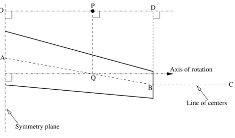
P Symmetry plane Line of centers A C B Q Axis of rotation O D
Figure 2: Definition of twist parameters for a swept wing
(∆Pijk)0≤i≤ni,0≤j≤nj,0≤k≤nk are weighting coefficients, or control points displacements, which
are used to monitor the deformation and are considered as design variables during the shape optimization procedure.
For the aerodynamic optimization, the FFD lattice is built around the wing with ξ, η and ζ in the chord-wise, span-wise and thickness directions respectively. The lattice is chosen in order to fit the planform of the wing (see figure 1). Then, the leading and trailing edges are kept fixed during the optimization by freezing the control points that correspond to i = 0 and i = ni. Moreover, all control points are only moved vertically. Hence for a parameterization of
ni×nj×nk, we obtain (ni−1) × (nj+ 1) × (nk+ 1) design variables. In all the test cases in this
work, we use nj = nk= 1; this leads to a linear interpolation of the root and tip airfoil sections
over the span.
3 Wing twist parameterization
The basic function of introducing wing twist is to induce a smaller angle of attack at the wing tip than at the root, known as washout. This leads to smaller induced drag and also prevents the wing-tip from stalling first, which can be undesirable from stability point of view. Moreover, by adding wing twist as a design variable, we can change the effective angle of attack of the wing which is very useful in lift-constrained drag minimization problems, since it is the angle of attack which has a major influence on lift. Twist can be parameterized as the solid body rotation of all the mesh points about a center and an appropriate axis of rotation. Axis of rotation (~n) can be arbitrarily chosen depending upon the orientation of the geometric model. In the present work, unit vector perpendicular to the symmetry plane of the wing is chosen as the axis of rotation.
Line of centers is the locus of all the centers of rotation. It may be divided into two or more line segments depending upon the shape of the wing. For example, for a double delta wing, the line of centers will be composed of three segments, two inside the wing and one on the outside going upto the outer boundary. In the present work, only a simple swept wing is considered and hence the line of centers ABC consists of two line segments as shown in figure (2): segment AB starting from root section and ending at the wing tip, and the other segment BC starting from
12’th Annual AeSI CFD Symposium, 11–12 August 2010, Bangalore
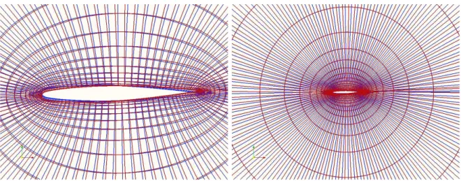
Figure 3: Grid in a plane perpendicular to the wing span: initial grid (blue) and grid after twist (red)
the wing tip and continuing till the outer boundary of the mesh in the direction of the axis of rotation. The location of the centers can be based on quarter-chord points or mid-chord points, this choice being controlled by the user through an input file.
Any point P is rotated about the point Q which is obtained by projecting P onto the line of centers ABC. The angle of rotation is parameterized as
θ(s) = (1 − s)θ0+ sθ1 (3)
where θ0and θ1 are the angle of twist at the wing-root and the wing-tip respectively while s ≥ 0
is defined as s = OP/OD with OD being parallel to the axis of rotation. It is also easy to use a higher degree polynomial to parameterize the rotation angle. Note that if Q lies between AB then s ∈ [0, 1] while if it is on BC we have s > 1.
In order to test the twist implementation, we take the case of Onera M6 wing at M∞= 0.84,
α = 3.06 deg. on an inviscid structured grid. A linear twist variation with θ0 = 0 and θ1 = 3
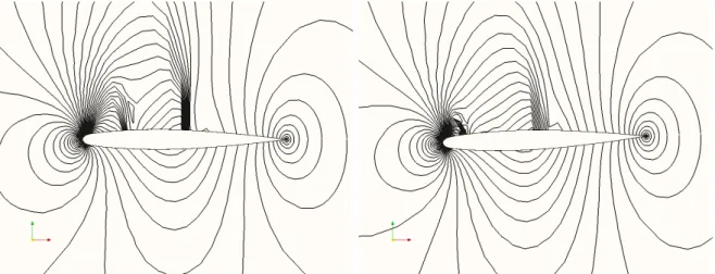
deg. is used. This causes the wing to pitch down at the tip leading to a reduction in the angle of attack. The initial and rotated grids are shown in figures (3) which shows a smooth grid even after twist. The grid rotation extends upto the outer boundary with an increasing amount of rotation; however since this rotation leads to a smooth deformation it does not degrade the quality of the grid. The flow was computed over the initial and twisted shapes and the pressure contours are shown in figure (4). After twist, the shock strength has been reduced due to the reduction in angle of attack; the lift and drag coefficients decrease as expected indicating the correct effect of wing twist.
The use of FFD and twist parameterization in shape optimization will be effected as a com-position of two shape deformations. The reference shape will be first deformed using FFD as explained in the previous section; then the shape will be twisted as detailed in this section. The resulting grid can then be analyzed by the CFD solver. This is schematically illustrated below:
FFD variables Twist variables
↓ ↓
Figure 4: Pressure contours on initial grid (left) and twisted grid (right)
4 Surrogate-based PSO
PSO is modeled on the behaviour of a swarm of animals when they hunt for food or avoid predators [6]. Consider the problem of minimizing a function J : D ⊂ Rd → R. A swarm
of particles wanders around in the design space D according to some specified velocity. The position of each particle corresponds to one set of design variables and it has an associated value of the cost function. Each particle remembers the best position i.e., having smallest function value, it has discovered in its entire lifetime (local memory) and also knows the best position discovered by its neighbours and the whole swarm (global memory). The velocity of each particle is such as to pull it towards its own local memory and the global memory of the swarm. Thus the motion of each particle is a compromise between exploring local regions of design space and the region around the global best solution. The particles cooperate in the sense that they all share the information of the global memory and this leads to efficient search for the optimum. While there are many variants of the PSO algorithm, the one we use is described in [4].
PSO is a global search method and has slow convergence property, typically requiring several thousand CFD computations for a realistic problem. In order to reduce the computational cost of PSO, the costly analysis tool (CFD) is replaced with a surrogate model ˜J. The optimization algorithm is applied to the metamodel ˜J to predict a better solution. However this cannot be a one-shot process since the metamodel is an approximation, usually very coarse, and the optimum solution predicted by minimizing it may not really be the optimum and/or may not satisfy the constraints. The metamodel must be updated by adding new data points and the optimization applied to the new model. This process is continued until some convergence criterion is satisfied or the computational resources are exhausted. The selection of the new evaluation points is the most crucial aspect of this method. New points must be added in those regions of the design space where there is more likelihood of the existence of an optimum. This is achieved by selecting the new evaluation points as the minimizers of the merit function(s), which are described in [8] together with a complete description of the algorithm.
The surrogate model is built using kriging [8], which not only gives an estimate ˜J of the exact function J but also gives an estimate of the error or standard deviation ˜s in the estimated value. Where the model is less accurate, perhaps due to sparse data, it will predict a large value of ˜s.
12’th Annual AeSI CFD Symposium, 11–12 August 2010, Bangalore
Torczon et al. [3] and Cox and John [2] suggested the use of the lower confidence bound of the prediction as a merit function defined as
fM(x) = ˜J(x) − κ˜s(x) (4)
The merit function is minimized and the new evaluation point is the minimizer of the merit function. Several merit functions with different values of κ are minimized which gives a set of new evaluations points. A small value of κ leads to searching around the current minimum of the metamodel. A large value of κ may be expected to give a good estimate of the lower bound of the cost function and leads to better exploration of the search space where the data is less certain or non-existent. According to [1], in practice using four different values of κ = 0, 1, 2, 4 is sufficient. In this case, in each optimization iteration, four CFD computations have to be performed and the results added to the database.
5 Optimization of Onera M6 wing
The standard Onera M6 wing at transonic flow conditions (M∞ = 0.84, α = 3.06 deg.) is
taken as a test case for optimization. An inviscid, finite volume solver [7] based on multi-block, structured grids, Roe fluxes and MUSCL scheme is used to compute the flow, which contains a lambda shock on the upper wing surface as seen in figure (6). The optimization problem is:
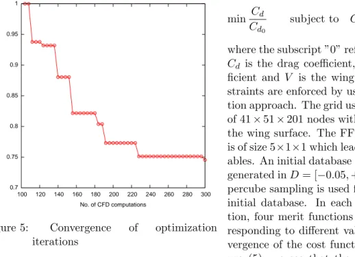
0.7 0.75 0.8 0.85 0.9 0.95 1 100 120 140 160 180 200 220 240 260 280 300 Cost function No. of CFD computations
Figure 5: Convergence of optimization iterations
min Cd Cd0
subject to Cl = Cl0 and V = V0
where the subscript ”0” refers to the M6 wing, Cd is the drag coefficient, Cl is the lift
coef-ficient and V is the wing volume. The con-straints are enforced by using a penalty func-tion approach. The grid used for CFD consists of 41 × 51 × 201 nodes with 35 × 201 nodes on the wing surface. The FFD parameterization is of size 5×1×1 which leads to 16 design vari-ables. An initial database of 100 design points generated in D = [−0.05, +0.05]16
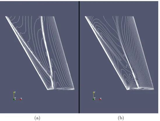
by latin hy-percube sampling is used for constructing the initial database. In each optimization itera-tion, four merit functions are minimized cor-responding to different values of κ. The con-vergence of the cost function is shown in fig-ure (5); we see that the drag is reduced by about 25% while the constraints are satisfied. Figure (6) shows that the shock has been consid-erably weakened as a consequence of shape optimization and this is reflected in reduced drag. Near the wingtips, the pressure contours show that the shock is still considerably strong. The result can perhaps be improved by including wing twist also as a design variable, which is an ongoing work.
(a) (b)
Figure 6: Pressure contours for (a) Onera M6 wing and (b) optimized wing
6 Summary and conclusions
A shape optimization framework for global optimization using PSO, surrogate models and FFD is presented. For wings, twist is an important design variable and a strategy is developed for incorporating it together with FFD. The current results with FFD alone show good performance of the optimization tool at a reasonable computational expense in terms of the number of CFD computations required (about 220 in this case), with a 25% reduction in drag coefficient, while the lift and volume constraints were satisfied. We hope to improve the results by using twist also a design variable and the results will be presented in the symposium.
References
[1] D. B¨uche, N. N. Schraudolph, and P. Koumoutsakos. Accelerating evolutionary algorithms with gaussian process fitness function models. IEEE Tran. on Systems, Man, and Cybernetics
- Part C: Applications and Reviews, 35(2), 2005.
[2] D. Cox and S. John. Sdo: A statistical method for global optimization. In N. M. Alexandrov and N. Hussaini, editors, Multidisciplinary Design Optimization: State-of-the art, pages 315– 329. SIAM, Philadelphia, 1997.
[3] J. E. Dennis and V. Torczon. Managing approximation models in optimization. In N. M. Alexandrov and N. Hussaini, editors, Multidisciplinary Design Optimization: State-of-the
12’th Annual AeSI CFD Symposium, 11–12 August 2010, Bangalore
[4] R. Duvigneau, B. Chaigne, and J.-A. Desideri. Multi-level parameterization for shape opti-mization in aerodynamics and electromagnetics using particle swarm optiopti-mization. Research Report RR-6003, INRIA, Sophia Antipolis, 2006.
[5] G. Farin. Curves and surfaces for computer-aided geometric design. Academic Press, 1989. [6] P. Miller. Swarm behaviour. National Geographic, July 2007. available online at
http://www7.nationalgeographic.com/ngm/0707/feature5/. [7] NUWTUN. http://nuwtun.berlios.de.
[8] C. Praveen and R. Duvigneau. Study of some strategies for global optimization using Gaus-sian process models with application to aerodynamic design. Research Report RR-6964, INRIA, 2009.
[9] T. Sederberg and S. Parry. Free-form deformation of solid geometric models. Computer