PSFC/JA-11-3
Configurable DC current leads, with Peltier elements
L. Bromberg, P. Michael, M. Takayasu and J.V. Minervini
March 2011
MIT Plasma Science and Fusion Center Cambridge MA 02139
Abstract
There is interest in decreasing the thermal load to the cryogenic environment from the current leads. The cryogenic load is challenging both at the design current, as well as at part load operation, when the current is reduced or zero. In this paper we explore the combination of a Peltier elements and a novel concept of configurable current lead. The use of Peltier element reduces the cryogenic load by about 25%. The configurable concept is based on the use of multiple heat exchangers that allows the optimization of current leads when operating at various currents. When used together,
Peltier/configurable current lead allows the reduction of the cryogenic load by a factor of 4 in low current/idle conditions. We also explore the transient operation of the current leads, as well as overload capacity.
I. Introduction
Current lead optimization has been of interest recently since the development of superconducting magnets, as the cryogenic load from the current lead constitutes, in many cryogenic applications, the dominant thermal load. Means of optimizing conduction cooled current leads have been developed by McFee [McFee], and
reproduced by Chang and van Sciver [Chang] more recently. The optimization consists of, for a given current and cross sectional area, finding the length at which the thermal load at the cryogenic environment is minimal. For lengths shorter than this, the thermal conduction increases faster than the Joule dissipation decreases, while for shorted leads, the reverse is true. Thus, an optimal configuration occurs, which is found to be given by the quantity I l/A, where I is the current, l is the length of the current lead and A is the cross sectional area.
While the quantity I l/A depends on the materials choice, it has been shown that the minimum is not sensitive to the choice of materials. This is due the Wiedemann–Franz relationship between thermal and electrical conductivity. However, there are choices for different materials due to other considerations, such as transients and response to
overcurrents. We have found out that aluminum alloys offer an advantage over copper [Bromberg1]. However, aluminum has problem with making reliable joints. We have used copper in the calculations in this paper.
It is interesting to notice that, for full current and steady state conditions, there is no advantage in adjusting the cross section of the current leads. The parameter of interest in that case is I ∫dx / A(x), where the integral is along the current lead, x.
More recently, interest in optimization of current leads has been renewed by advances in high temperature superconductors, and applications to energy grid, such as power transmission and distribution, and energy storage. For military applications, were size and weight are important [Haught.O’Rourke, Fitzpatrick], HTS offers a near term alternative to heavy copper bus bar. However, the electrical power requirements and the size and weight of the refrigerators represents a substantial parasitic load on the systems,
and as a consequence there is interest in minimization of the cryogenic load at full and partial load.
We have developed configurations to minimize the cryogenic requirements, which are important for power transmission applications (both for the minimization of the
cryoplant, as well as to decrease the power requirements for the refrigerators). Previous work has used a multiple temperature stages, resulting in thermal loads intercepted at higher temperatures, where Carnot efficiencies (and corresponding thermal efficiencies) of refrigerators are higher. [Bromberg]
An interesting approach has been developed by Yamaguchi and his colleagues [Sato], where thermoelectric elements are used in series with the current lead. In this paper we investigate the characteristics of high performance thermoelectric elements, using properties developed by Research Triangle Institute [RTI].
In this report we discuss options for minimization of the heat leak under conditions where the current is lower than design value. Section II discussed the Peltier current lead
coupled to a configurable current lead.
II. Peltier current lead
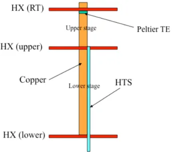
The configurable current lead concept being investigated is shown in Figure 1. The model includes a TE (thermoelectric) element at the warm temperature side of the current lead, and two heat exchangers. The upper heat exchanger (HX upper) near the warm end of the current lead is inactive under low current operation, in order to extend the effective length of the current lead and minimize the heat leak. Under these condition the lower heat exchanger (HX lower) is active. When operating at full or high current, the upper heat exchanger is active. The effective length of the current lead can be adjusted in order to minimize the heat leak at variable currents. It should be noted that there is an HTS tape that shunts the current lead between the upper and lower heat exchangers.
The effective length of the current lead can be adjusted by directing the flow to a selected heat exchanger. The process involved some valving at the cryogenic environment, but otherwise is simple.
The magnitude of the cryogenic load savings has been described before without the use of the TE element. [Bromberg] In this section, the impact of the Peltier TE element as well as current lead length on the cryogenic heat leak will also be presented.
Figure 1 Current lead with Peltier element and multiple heat exchangers (but single cryocoolant).
It is interesting to investigate the possibility of the two-stage configurable concept with a Peltier element. The advantage of the Peltier element is that it is passive, although it complicates the assembly of the unit. A potential concern is performance of the Peltier element under over loads conditions. Both of these issues are addressed in this section.
There are a variety of Peltier elements available commercially and semi-commercially. We have considered high performance TE materials developed by Research Triangle Institute [RTI], materials that are referred to as to nanomaterials. However, temperature dependence of these materials has not been measured. We have assumed that the
temperature dependence of the RTI material is similar to that of the material properties measured by Kawahara and Yamaguchi [Kawahara]. The properties of Yamaguchi materials are shown in Figure 2, while those of the RTI materials (with known properties at 300 K) are shown in Figure 3. Alpha is the TE constant, while eta is the electrical resistivity. The thermal conductivity is 2.5 W/K m, relatively independent of
temperature.
Figure 2. Measured temperature dependence of the Seebeck coefficient (alpha) and electrical resistivity (eta) for the material tested by Yamaguchi group [Fujii]
Figure 3. Assumed temperature dependence of the Seebeck coefficient (alpha, V/K) and electrical resistivity (eta, Ohm-m) for the RTI material.
The formulation that we have used in this report is similar to that by Jeong. [Jeong] The heat flow along the TE element, and the current flowing through it, are given by
where α, ρ and k are the Seebeck coefficient, electrical resistivity and thermal
conductivity of the lead material, respectively. A denotes the cross-sectional area and V denotes the electro-chemical potential. α is zero for both the metal and HTS. The sign in front of α is (+) for a p-type TE and (-) for an n-type TE.
III. Full current operation
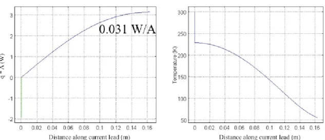
The temperature profile and the heat load (q*A) along an optimized current lead are shown in Figure 4 for the case of 100 A. As in the case of conduction cooled current leads, the cryogenic load is minimum when the gradient at the high temperature side (downstream from the TE), is 0. This condition means that there is no heat flow across the TE-metal interface. Note that the temperature has a large drop across the TE element. It is assumed that the cross sectional area of the TE element and the copper lead is A = 4 mm2 and a length of 300 microns. The corresponding length of the optimized current lead, for 100 A, is 16.3 cm. The minimum power, from room temperature to 55 K, is 0.031 W/A.
Conventional current leads (single stage) have a heat leak of 0.42 W/A (for same material properties; see [Bromberg]) when using copper. Thus, when using a TE element, the cryogenic load is decreased by ~ 25%.
Figure 4. Thermal load and temperature profile for an optimized TE/current lead. Note the large temperature drop along the TE element.
IV. Partial current and overcurrents.
Next we address the question of the performance of an optimized current lead when operating at different currents than the optimum. We have found out that the performance is strongly dependent on the boundary condition at the high temperature side. There are two types of boundary conditions at the warm end of the current lead: clamping the temperature or having an effective heat transfer coefficient. In the case of water cooling of the warm end of the current lead, the boundary condition is most likely to be constant temperature, while for air cooling, and in particular natural convection cooling in air, the effective heat transfer boundary condition (q = h A ΔT) is more applicable. The issue is relevant both when operating at higher currents and at lower current (at design current, the thermal gradient at the warm end of the copper lead is zero. With a clamped temperature, the peak temperature along the current lead during overcurrent is
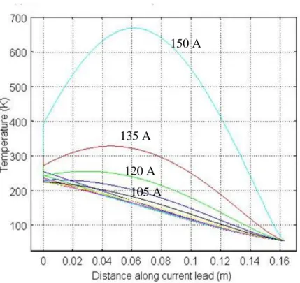
substantially reduced. Figure 5 shows the temperature profiles for currents different than the optimal current, for CLAMPED temperature at both sides (300 K at warm end, and 55 K at the cold end). The TE element provides cooling for currents less than 135 A, above that, the TE element results in heating. For 150 A, the resistive heating of the TE
exceeds the cooling, and the temperature at end of the TE element is about 400 K, or about 100 K warmer than the boundary condition.
The peak temperature along the current lead occurs near the middle, as there is
substantial heat being transferred to the warm end. It is this temperature clamping that helps control the temperature and allows for the large overcurrent.
Figure 5. Temperature along the short section of the current lead, for currents other than the optimized current; current in steps of 15 A.
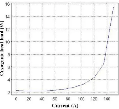
Assuming a maximum temperature along the current lead of 600 K, with good cooling at the high temperature side it is possible to drive about 150 A. That is, the overcurrent capability is about 1.5, for steady state conditions, as long as the cryogenic system can support the increased heating. Figure 6 shows the heat leak as a function of the
overcurrent, corresponding to the currents in Figure 5. 150 A
135 A 120 A
Figure 6. Cryogenic heat load (to the 55 K environment), as a function of the current through a current lead optimized for 100 A. At 100 A, the heat load is 3.1 W.
The heat load at 150 A is about 5 times the heat load at 100 A. The heat load is substantially higher than just I2 (which would be a factor of about 2), because of the higher temperatures along the current lead results in higher Joule dissipation and the temperature gradients are higher, as the peak temperature occurs half way through the current lead.
V. Configurable current lead
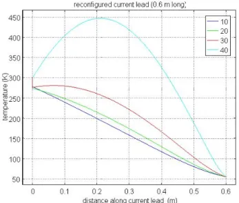
When operating at lower currents, it is possible to place the HX at the location indicated in Figure 1 as HX lower, effectively increasing the length of the conformable current lead. It is assumed that at the lower location of the HX, the lead is 0.6 m long. The corresponding heat leak, when operating at 25 A, is 0.7 W, or about 1/3 that of the
original 0.15 m current lead when operating at that same current (see Figure 6). Figure 7 shows the temperature profile along the current lead when operating over a range of
currents, from 10 A to 40 A, in steps of 10 A. At zero current, the thermal load is ¼ that of the shorter current lead.
Figure 7. Temperature profile along a long, reconfigured current lead.
VI. Transients
We have investigated the transient performance of the current lead, to learn about the limitations due to finite heat conduction along the current lead, separate from the limitations of the HX. Thus, in this section, it is assumed that the temperatures at the boundaries of the HX adjust instantaneously. The issue arises due to the fast change in current, from low or zero current to high current, and boundary conditions. The
temperature along the current lead is higher at the start of the transient, and we need to determine the conditions that result in stable lead operation and prevent burnout.
There are different limitations on the upper stage and lower stage, when the current lead is re-configured. The short section of the current lead during a transient from
low-current/stand-by to high current operation can handle currents as high as 150 A, when the HX-upper is instantaneously cooled to 55 K when ramping up to high currents. The transient lasts about 10 seconds for 100 A and about 50 s for 150 A.
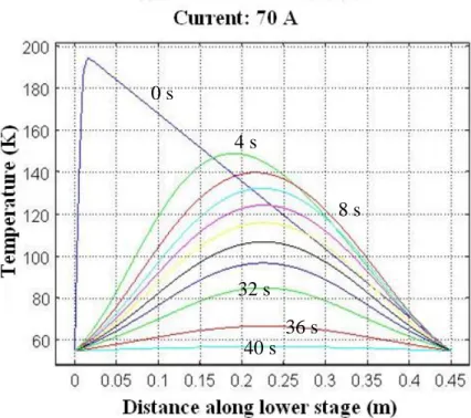
The main limitation of the transient performance of the current lead is due to the lower stage, recooling from the initial temperature distribution along the current. For the lower stage, the maximum instantaneous current that recovers is about 70 A, as shown in Figure 8. The recovery time is on the order of 20 s, increasing with increasing current. Higher currents would burn up the lower stage. Thus, during transition, there is a brief limitation on maximum power through the current lead, about 10-20 s, during which a limited power can be transmitted, before full power can be engaged. The delay to full power is a negative consequence from the use of the configurable current lead.
Figure 8. Transient on the lower stage of the current lead after a transient from low current to high current, operating at 70 A. 4 seconds between profiles. The x-coordinate is measured along the current lead, from the upper HX (on the left) to the lower HX (on the right).
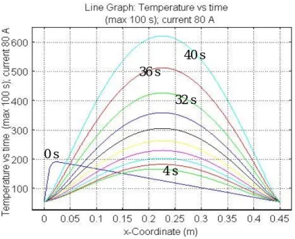
If the current during the transient is slightly higher than 70 A, the performance of the current lead is very different. Figure 9 shows the temperature profiles along the current lead for a current of 80 A held constant. The temperature increases over the bulk of the
0 s 4 s 8 s 40 s 36 s 32 s
current lead, and keeps on increasing during the duration of the simulation. If it is not shut down, the current lead will burn out. After the transient, full current (or overcurrent) can be established.
Finally, assuming that the cable can tolerate overcurrents, by operating pulse it is possible to increase the operating current in the current lead. Table 1 shows the results, assuming a maximum operating temperature of 600 K. Substantial overcurrents are possible, limited by the HTS cable.
Figure 9. Temperature profile along the current lead for 80 A transient. Profiles are in 10 s intervals, starting with a linear profile. The x-coordinate is measure along the current line, from the upper HX to the lower HX
Table 1. Time to 600 K (in seconds) for different pulsed currents (current lead optimized for 100A) current time to 600 K (s) 150 25 200 2.5 300 0.75 400 0.4 0 s 4 s 40 s 36 s 32 s
VII. Conclusions
In this paper we have investigated the combination of PCL with configurable current lead as a means to reduce the cryogenic load during full and partial operation. We have shown that it is possible to decrease the load by about 25% at full load, and by about a factor of 4 at partial/stand-by conditions.
The transients during current-lead reconfiguration (from low current to high current), indicate that power is limited to partial power for times on the order of 1 minute, before full current/overcurrent can be established. During this transition time, the current lead is limited to ~ 0.7 of full current.
References
[Bromberg] Bromberg, L., Michael, P.C., Minervini, J.V., and Miles, C., Coolant topology options for high temperature superconducting transmission and distribution systems, AIP Conference Proceedings 1218, 2010b, pp. 871-8 [Bromberg1] Bromberg, L., Michael, P.C., Minervini, J.V., and Miles, C., Current lead
optimization for cryogenic operation at intermediate temperatures, AIP Conference Proceedings, 1218, 2010a, pp. 577-84
[Chang] Chang H-M and Sciver S.W.V., Thermodynamic optimization of conduction-cooled HTS current leads, Cryogenics 38 729–36 1998
[Fujii] T. Fujii, S. Fukuda1, M. Emoto, Thermoelectric property dependence of heat loss reduction for Peltier current lead using high conductive thermoelectric materials, presented at the 29th International Conference on Thermoelectrics, Shanghai, China, June 2010
[Haugan] Haugan, T.L., Long, J.D., Hampton, A., and Barnes, P.N., Design of Compact Lightweight Power Transmission Devices for Specialized High Power
Applications, Presented at SAE 2008 Power Systems Conference, 2008
[Jeong] Jeong, E.S., Optimization of conduction-cooled Peltier current leads, Cryogenics 45, 2005, pp. 516–522
[McFee] McFee, R., Optimum Input Leads for Cryogenic Apparatus, Rev Scientific Instr 30, 1959, pp. 98–102
[O’Rourke] O’Rourke, R., “Electric-Drive Propulsion for U.S. Navy Ships: Background and Issues for Congress,” Congressional Research Service Report for Congress, RL30622, July 31, 2000
[Sato] Sato, K, Okumura, H and Yamaguchi, S., Numerical calculations for Peltier current lead designing, Cryogenics 41, 2001, pp. 497-503.
[RTI] Venkatasubramanian, R., Senior Research Director, Center for Solid State Energetics (CSSE), RTI International, private communication (2010)
![Figure 2. Measured temperature dependence of the Seebeck coefficient (alpha) and electrical resistivity (eta) for the material tested by Yamaguchi group [Fujii]](https://thumb-eu.123doks.com/thumbv2/123doknet/14452224.518823/6.918.141.755.302.586/measured-temperature-dependence-seebeck-coefficient-electrical-resistivity-yamaguchi.webp)