HAL Id: hal-03210802
https://hal.archives-ouvertes.fr/hal-03210802
Submitted on 28 Apr 2021HAL is a multi-disciplinary open access
archive for the deposit and dissemination of sci-entific research documents, whether they are pub-lished or not. The documents may come from teaching and research institutions in France or abroad, or from public or private research centers.
L’archive ouverte pluridisciplinaire HAL, est destinée au dépôt et à la diffusion de documents scientifiques de niveau recherche, publiés ou non, émanant des établissements d’enseignement et de recherche français ou étrangers, des laboratoires publics ou privés.
Frugal innovation for sustainable rural electrification
Bunthern Kim, Chrin Phok, Maria Pietrzak-David, Pascal Maussion
To cite this version:
Bunthern Kim, Chrin Phok, Maria Pietrzak-David, Pascal Maussion. Frugal innovation for sustainable rural electrification. EPE’20 ECCE Europe, Sep 2020, Lyon, France. pp.1-9. �hal-03210802�
OATAO is an open access repository that collects the work of Toulouse
researchers and makes it freely available over the web where possible
Any correspondence concerning this service should be sent
to the repository administrator:
tech-oatao@listes-diff.inp-toulouse.fr
This is an author’s version published in:
https://oatao.univ-toulouse.fr/2
7210
To cite this version:
Kim, Bunthern and Phok, Chrin and Pietrzak-David, Maria and Maussion, Pascal Frugal innovation for sustainable rural electrification. (2020) In: EPE'20 ECCE Europe, 7 September 2020 - 11 September 2020 (Lyon, France).
Official URL:
https://doi.org/10.23919/EPE20ECCEEurope43536.2020.9215876
Frugal Innovation for Sustainable Rural Electrification
Bunthern Kim
(1)(2), Phok Chrin
(1)(2), Maria Pietrzak-David
(1), Pascal Maussion
(1)(1)
LAPLACE, UNIVERSITÉ DE TOULOUSE, INP, UPS, CNRS, Toulouse, France,
(2)
INSTITUTE OF TECHNOLOGY OF CAMBODIA, Phnom Penh, Cambodia,
Phone: +33 5 34 32 23 59, +33 5 34 32 23 64, Fax: +33 5 61 63 75 88
bunthern.kim@laplace.univ-tlse.fr
,
pchrin@itc.edu.kh
,
Maria.David@laplace.univ-tlse.fr
,
Pascal.Maussion@laplace.univ-tlse.fr
,
Keywords
«Induction motor», «Generation of electrical energy», «Generator excitation system», «Photovoltaic», «Sustainable system/technology»
Abstract
In this article an original solution is proposed by using wasted electric and electronic equipment (second-life components) to create the new power generation systems for remote rural areas. This frugal innovation for rural electrification guarantees an important support social, educational and economic development goals especially in Southeast Asian countries.
Introduction
The use of second-life components, available at low cost locally, can prove to be a viable solution for the electrification of isolated villages in developing countries. If based on renewable energies, they contribute to the fight against global warming and can promote economic development and education. With local available energies, for example biogas or electricity, better education, reduced time for collecting wood, access to information or entertainment (TV, radio, laptops), improve economic activities, human health and life could be better. Indeed, many electrical and electronic products are often discarded even before their end of life [1], for reasons of fashion, marketing or change of use. This leads to an increase in the consumption of energy and raw materials. The innovative solutions proposed in this paper could offer to a new sustainable economic strategy developing countries. This study focuses, of course, on the application of WEEE reuse in a stand-alone renewable energy system as a solution for electrification in rural areas in some developing countries. Solar, hydro or wind energy are chosen thanks the outcomes of many international reports such as [2] in a global survey regarding the energy access in the Least Developed Countries. Moreover, these energies have also been selected by many of these countries in their Intended Nationally Determined Contribution [3] for COP21, in 2015.
The different architectures developed in this study are described in next section. They include two parallel energy sources: solar panels and hydraulic generation and energy storage in in lead-acid batteries. Re-use power electronic devices with minimum modifications are used for DC/DC or DC/AC or even AC/DC conversions of energy. Different solutions have been proposed for this objective, but the main idea of this study concerns the research of minimal modifications in the existing products, so as not to increase the environmental impacts and also encourage a large dissemination. The main elements of a Life Cycle Analysis (LCA) of the solar chain are given in [4]. The minimum modifications of one ATX PC Power Supply Units (PSU) are presented and an MPPT is implemented in a Arduino microcontroller. Moreover, this sections also provides some experimental results of several PSU associations in order to increase the supplied power. Finally, simulations and tests on a test bench, with a 1,5kW 3 phase induction motor used as a single phase generator validate the system feasibility.
Global presentation of frugal solution
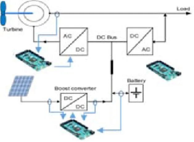
The global architecture of the studied system is shown in Fig. 1. It consists of two interconnected "solar" and "hydraulic" lines. The solar chain includes photovoltaic (PV) panels and a Personal Computer (PC) power supply (PSU) instead of a commercial solar converter. We opt for a Maximum Power Point Tracking (MPPT) control strategy which has been successfully implemented in an Arduino Due Microcontroller. This microcontroller is very popular because of its low cost, its high availability in the market and its open source software.
Fig. 1: Rural electrification architecture
The hydraulic line includes a second life squirrel cage induction motor which has been purchased from a local scrap dealer (Fig. 2) and a voltage source inverter (VSI), initially dedicated to supply PCs as emergency network (DC/AC converter). The energy storage will be provided by second-life automotive lead-acid batteries.
Fig. 2: Induction recovery motors in Cambodia (low cost second hand products from China, Taiwan, Malaysia, Thailand…)
Since the original objective of this frugal innovation is the electrification of remote villages in Southeast Asian countries, the functional unit is defined to satisfy the daily energy needs of a rural village over a period of 20 years. The load profile of a typical small village in Thailand [5] was chosen for this case study (Fig. 3).
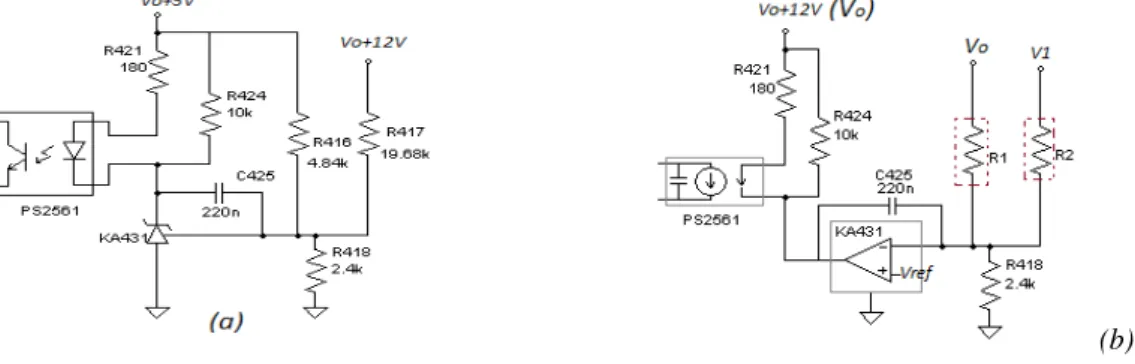
This functionality does not fit the requirements of small renewable energy systems which provide low input DC voltage (100V) and need variable output voltage. Figure 5 shows the components which have been modified. Firstly, the protection functionality of WT7517 should be removed to allow the converter to be used independently of the limitation of the standard power supply. In addition, the range of the PSU’s input voltage should be reduced by using the primary side center tap pin of the main transformer. Detailed analysis and modifications are shown in figures 6 and 7. The objectives of the feedback circuit modifications are that the output voltage can be changed by the controller through an external input voltage, given by a MPPT microcontroller for example. The different modifications are depicted in Figures 6.a and 6.b.
(b) Fig. 6: Initial (a) and modified feedback (b) circuits
Then, the Schottky diodes, resistors, capacitors, inductors of the +5V, +3.3V and -12V circuits are removed and the second Schottky diode of the +12V circuit has to be grounded. After these modifications, shown in Figure 7, only the +12V works while the 5VSB is generated from another part of the converter.
(a) (b)
Fig. 7: +12V circuit scheme before modification(a) end after (b) modification
A problem on the +12V circuit has to be solved: the maximum output voltage cannot exceed 16V, due to output filter capacitor ratings. The solution is the serial insertion of another capacitor (to increase the voltage) and a parallel connection of two identical legs to come back to the initial value of the capacitance.
The detailed analysis and experimental results are presented in [8].The value of the resistors R1 and R2
in Fig. 6b are changed from 10kΩ to 18kΩ in order to avoid the ground problem and use any PSU without any danger. The relation of Vo and V1 at steady state can be written by (1) and the output value
Vo can be controlled by the injected signal V1 following the relation (2).
(
1+
R
418R
1+
R
418R
2)
V
ref=
R
418R
1V
o+
R
418R
2V
1 (1)V
o=20−V
1 (2)As a consequence of this section and without the need for a new printed circuit board, contrary to [4], this initial AC/DC static converter with regulated fixed output voltage is transformed into a DC/DC converter with variable voltage (or current) controlled. The complete modifications on the PSU are described in [8] and [9].
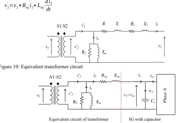
The equivalent circuit of this transformer is shown in the Figure 10. Its primary winding parameters, resistance R1 and reactance X1, are referred to secondary winding, i.e. R1’=(N2/N1)2R1, X1’=(N2/N1)2X1
So, the equivalent resistance Req and reactance Xeq can be expressed as shown in the Fig. 11:
Req=R’1+R2, and Xeq=X’1+X2 , (Xeq=2πf Leq). The transformer output voltage can be expressed as
follows:
v
'2=
v
2+
R
eqi
2'+
L
eqd i
2 'dt
(3) v2 Xm R2 X2 R X i2 v'2 N1:N2 v1 io RC i'2Figure 10: Equivalent transformer circuit
Xm Req Xeq v'2 N1:N2 v1 io RC i'2 Ce iCe ise v2=vse ie Pha se A IG with capacitor i2
Equivalent circuit of transformer
Figure 11: Equivalent circuit of transformer and EIG with capacitor [12]
As shown in the Figure 11, the transformer secondary winding is connected to the excitation phase A of EIG. So, the v2’=vse and i2=ie. In fine, the state space equation describing the EIG behavior is
formulated as below:
˙
xT=
[
AT]
xT+[
BT]
uT (4)with
x
T=
[
i
ev
sev
soi
sei
soi
rαi
rβ]
Tsystem state space vector andu
T=
v
2' system input, expressed by (3). The system matrices are expressed as follows:[
A
T]
=
[
[
A
T 1] [
A
T 2]
[
A
T 3] [
A
T 4]
]
,[
AT 1]
=[
−Req/Leq]
,[
AT 2]
=[
−1/ Leq 0 0 0 0 0]
;[
AT 3]
=[
Bc]
,[
AT 4]
=[
Ac]
,[
B
T]
=
[
1/ L
eq0
6× 1]
The matrices [Ac] and [Bc] are defined from the EIG modeling with capacitors Ce and C0 only.
[
A
c]
=
[
A
c0A
c 1[
B
]
[
A
]
]
,[
B
c]
=
[
1/C
e0
2 ×2]
T with[
Ac 0]
=[
00 −1/ R0 LCo]
,[
A
c 1]
=
[
−1/C
e0 0 0
0 −1/C
o0 0
]
The matrices [A] and [B] were defined in our previous study concerning the EIG modeling [12]. Finally, the dynamic system matrix [AT] corresponds to the 7th order system written as follows:
[
AT]
= −Req Leq −1 Leq 0 1 Ce 0 0 0 0❑ ❑ −1 CoRL ❑ ❑0 0 0 ❑ ❑− 1 Ce 0 0 0 −1 Co 0 0❑ ❑ 0❑ ❑ 0❑ ❑ 0 −Lrr L1 0 0 0 −Lrr Lb 0 Lms L1 0 0 0√
3 Lms Lb RsLrr L1 −√
3 Lms2 ω r L1 −RrLms L1√
3 Lms2 ωr L2 2 RsLrr L2 −√
3 LmsωrLrr 6 L2 −RsLms L1 at(5 ,4) Rr(
Lls+Lms)
L1 −2 LssLmsωr L2 −2√
3 LmsRs L2 at(6 ,5) LmsωrLrr 6 L1 −√
3 RrLms L2 at(5 ,6)❑ ❑ 2 RrLss L2 (5)w
ith at(5 ,4)=√
3(
Lls+Lms)
Lmsωr L1 , at(5 ,6)= 6 ωrLs 1−7 Lms2 ωr 6 L1 , at(6 ,5)= 7 Lms2 ωr−4 ωrLs2 2 L2 ,r – rotation speedLls -leakage inductance of stator winding, Lms- maximal value of magnetizing inductance of stator
winding
As this system is non stationary, its dynamics using pole locus evolutions and frequency responses were analyzed according to the parameter variations to find most preponderant of them modifying the system behavior [13]. This analysis helps to design the voltage control which will be discussed with details in final version of this article.
Output voltage control of the EIG
The output voltage of the push pull inverter is controlled by its duty ratio thanks to a feedback loop, given below. The output voltage of EIG depends on its excitation voltage vse and its rotation speed. In
this application of power generation output voltage and frequency must be always kept constant even in any disturbance condition. Moreover, in hydropower applications rotation speed variations are not easy to manage, except in high quality hydropower stations. Consequently, speed and load current variations will be considered as system disturbances. Our experimental set up of an EIG 1.5kW and disposal UPS are shown in Fig. 12.
P P
(c) FFT of output voltage when load power 200W
P P
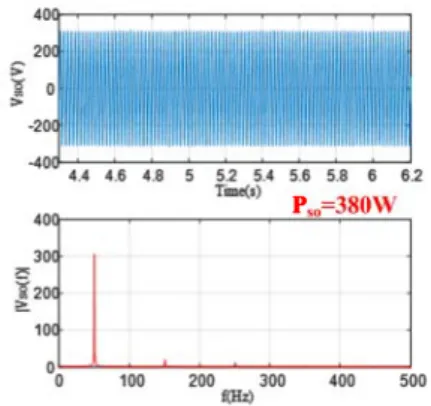
(d) FFT of output voltage when load power 380W
Fig. 13: Experimental results with PI control: voltage response of the 1.5 kW IG with reuse UPS during step load change (Fsw=50Hz, RL=240Ω- 127Ω -240Ω, Ce=20µF, Co=10µF)
The output voltage raises/drops about 55V (peak voltage in Fig. 13) and gets back to its reference with a settling time around 200ms. System voltage is stable and at the required amplitude after the transient due to load disturbances and its frequency remains constant as the excitation voltage is always 50 Hz, as shown in FFT analysis (Fig. 13 (c) and (d))
Conclusion
In this paper some innovative and original frugal solutions for rural electrification are presented and tested. The obtained experimental results are very encouraging. They are based on modeling, sizing, characterization and control of re-used materials for rural electrification in developing countries. In final version this study will supplemented by a life cycle analysis that justifies the choice of environmental impacts avoided. The reused components of power electronics and also the EIG, presents very attractive economically suitable solution for rural electrification of developing countries. Low cost of local components and frugal proposed innovative solution for rural electrification allows a creation of new life conditions for local peoples and also new future local jobs concerning all light modifications of reused products.
References
[1] Blenkinsopp, T.; Coles, S.R; Kirwan, K.; 2013. Renewable energy for rural communities in Maharashtra. India, Energy Policy, Volume 60, pp 192-199
[2] The Least Developed Countries Report 2017, Transformational energy access. United Nations Conference on Trade and Development, United Nations Publication (UNCTAD/LDC/2017).
http://unctad.org/en/PublicationsLibrary/ldcr2017
[3] Intended Nationally Determined Contribution (INDCs), as communicated by Parties for the COP21. http://www4.unfccc.int/submissions/indc/Submission%20Pages/submissions.aspx
[4] Kim, B.: Contribution to the design and control of a hybrid renewable energy generation system based on reuse of electrical and electronics components for rural electrification in developing countries, 2019, PhD thesis at Toulouse INP
[5] Ketjoy,N. : Photovoltaic Hybrid Systems for Rural Electrification in the Mekong Countries, 2005, PhD Thesis at University of Kassel
[6] Nayak,C.K.; Nayak,M.R.: Optimal size and cost analysis of standalone PV system with battery energy storage using IHSA, International Conference on Signal Processing, Communication, Power and Embedded System, SCOPES, 2016
[7] Rogers,D.; Green, J.; Foster, M.; Stone, D.; Schofield, D.; Abuzed, S.; Buckley, A.: Repurposing of ATX computer power supplies for PV applications in developing countries, International Conference on Renewable Energy Research and Applications, ICRERA, 2013.
[8] Hop Dinh, T.B.; Phan,Q.D.; Mausion, P.: Associations of Second Life of Power Supply Units as Charge Controllers in PV System, IECON 2018, Washington, USA,
renewable energy applications”, EPE 2015, Suitzerland
[10] Rogers, D.; Green, J.E.; Foster, M.P.; Stone,D.A.; Schofield, D.; Buckley, A.; Abuzed, S.: ATX power supply derived MPPT converter for cell phone charging applications in the developing world, 7th IET International Conference on Power Electronics, Machines and Drives, PEMD 2014
[11] Sera, D.; Mathe, L.; Kerekes, T.; Viorel Spataru, S.; Teodorescu, R.: On the Perturb-and-Observe and Incremental Conductance MPPT methods for PV Systems, IEEE Journal on Photovoltaics, Vol.3, N° 3, July
2013
[12] Chrin, P.; Maussion, P.; Pietrzak-David, M.; Dagues, B.; Bun, L.: Modeling of 3-phase Induction Machine As Single Phase Generator for Electricity Generation from Renewable Energies in Rural Areas, IEEE International Electric Machines and Drives Conference, IEMDC 2015, USA
[13] Chrin, P.: Contribution to electric energy generation for isolated-rural areas using 2nd life components and renewable energies: modelling and control of an induction generator, 2016 PhD Thesis at Toulouse INP [14] Ziegler, J.G.; Nichols, N.B.: Optimum settings for automatic controller, Transaction, ASME 1942, vol. 64, pp. 759–768,