Commanding Small Satellites for Simulated
Spacecraft Inspections Using Augmented Reality
MASSACHUSETS INSTITUTE
by
OFTECHNOLOGYJessica Eve Todd
OCT 09`2019
B.S., University of Sydney (2016)
LIBRARIES
0)
B.E., University of Sydney (2016)
Submitted to the Department of Aeronautics and Astronautics
in partial fulfillment of the requirements for the degree of
Master of Science
at the
MASSACHUSETTS INSTITUTE OF TECHNOLOGY
September 2019
oMassachusetts
Institute of Technology 2019. All rights reserved.
Signature redacted
A u th or ...
Department of Aeronics and Astronautics
August 22, 2019
Certified by
...
Signatureredacted
...
Lea7A. Stirling
Charles Stark Draper Assistant Professor of Aeronautics and
Astronautics
Thesis
SupervisorAccepted by
...
Signatureredacted
...
Commanding Small Satellites for Simulated Spacecraft
Inspections Using Augmented Reality
by
Jessica Eve Todd
Submitted to the Department of Aeronautics and Astronautics on August 22, 2019, in partial fulfillment of the
requirements for the degree of Master of Science
Abstract
Free-flying teleoperated satellites have been proposed as a replacement for astro-naut extravehicular activities (EVA), such as inspection or maintenance, to reduce astronaut risk. A major concern for this type of operation is ensuring the human operator has sufficient spatial and temporal knowledge of the free-flying spacecraft and environment to safely complete the task. This research evaluates Augmented Reality (AR) as a means of providing spatial and temporal information to an oper-ator controlling a free-flying robot to perform an inspection task. Specifically, the research focuses on the effect of command input mode and environmental risk on performance of an EVA inspection task and the strategies adopted by the operator in completing the inspection.
Subjects performed a simulated inspection task of a space station using an in-spector small satellite and the Microsoft Hololens platform. Subjects commanded the inspector satellite in three operation modes; satellite body (local) reference frame control, global reference frame control, and global waypointing system (placing mark-ers for the inspector to follow in the global reference frame). Subjects were instructed to inspect the exterior of the station and identify any surface anomalies. Anomalies could occur in areas with low and high risk of contact with the station structure. Subjects performed the inspection task using each of the three fixed command modes (order randomized), with different anomaly configurations. Subjects then performed the inspection task but with free choice of when and how often they utilized the different control modes. Performance was evaluated through primary task measures including percentage of station inspected and accuracy in locating anomaly sites,
number of AR interactions, and number of collisions with the station. Workload was also assessed using the NASA TLX survey.
Operation in both the global and local frame controls was found to maximise the percentage of the station that could be inspected, while the waypoint system was found to minimize the number of collisions between the inspector and the station. When operating with free choice of command mode, subjects preferred to stay in a single mode, typically either the global or local controls, likely due to the high usability of these modes for the selected inspection task. Environmental risk area was not found to have a signficant effect on either detection of anomalies or number of collisions.
Findings of this paper will inform a follow-on study at NASA's HERA facility, with a full analog-crewed mission operating multiple inspection agents over several days.
Thesis Supervisor: Leia A. Stirling
Title: Charles Stark Draper Assistant Professor of Aeronautics and Astronautics
Engineering is the art of modelling materials we do not wholly under-stand, into shapes we cannot precisely analyse so as to withstand forces we cannot properly assess, in such a way that the public has no reason to suspect the extent ofour ignorance.
Acknowledgments
This Masters thesis would not have been possible without the support of some amaz-ing people in my life. Firstly, I have to give a huge thank you to my amazamaz-ing advisor Leia Stirling. It has been a privilege to be guided and mentored by you over the past two years. Thank you for always listening, and for supporting me through the tough times. You're an amazing role model to me and to young female engineers.
Thank you to Andy Liu, for your continual guidance and insights, for reading my emails and drafts, and always taking the time to answer my questions. To Dave Miller, thank you for financially supporting me when funding situations became uncertain and for being a great source of advice in navigating potential career paths. To my UROPs, Emma and Josh, you were truly amazing. Despite endless debugging and hardware issues, you put in 110%, so thank you for all your hard work.
To the amazing humans of the Humans Systems Lab, I could not have asked for a better grad school family. Two years of Thanksgiving turkey extravaganzas, epic (and unfinished) movie lists, and team Halloween costumes, who could ask for more? The support, friendship, and camaraderie I've found in this lab is unmatched and has helped make MIT a second home.
To the wonderful Liz, Beata, Beth, Joyce, and Pam, I don't think the Department could manage without you. Thank you so much for all you do for us grad students in making this department such a supportive and welcoming place to work.
My phenomenal friends, Ben for being an amazing GA3 co-president, Cadence for
being the world's best roommate, Colin for keeping me sane with sailing and Boston adventures, and all my friends in AeroAstro, you've been my home away from home. The memories I have from the past two years are some of my happiest and I feel so grateful to have met you all. They say grad school takes a village, and you've been
mine.
And finally to my amazing family. The last two years have been tough, stretched across two continents and working on three degrees between us, but through it all, your support, love and encouragement has been a source of strength. To my amazing siblings Isabella and Reilly, you're both a constant source of inspiration to me. Early morning/late night FaceTime chats about everything from movies to the state of the Universe have gotten me through all the stresses and struggles of grad school. To my amazing dad, you've been my sounding board through all the ups and downs, giving career advice, listening when I've had a bad day or yet another existential crisis, and always having a fun science anecdote to keep me amused. I aspire to be an engineer and a leader like you. And to my phenomenal mum, I wouldn't have got here without your strength, love and support. Of all the amazing women I've been privileged to meet here and out in the world, you're still my biggest hero and source of inspiration.
Contents
1 Introduction
1.1 Background and Motivation . . . . 1.2 Previous Literature . . . . 1.2.1 Free-flying Robots for Space . . . . 1.2.2 Teleoperation Interfaces for Free Flying Robots
1.2.3 Command Modes in Telerobotics . . . .
1.2.4 Virtual and Augmented Reality Interfaces . . .
1.2.5 Performance measures in telerobotics . . . .
1.3 Research Gaps and Thesis Objectives . . . . 1.4 Thesis Outline . . . . 2 Development of Augmented Reality Interface
2.1 On-Orbit Task Concept . . . .
2.2 Augmented Reality Interface Development . . . . 2.2.1 H oloLens . . . .
2.2.2 Gestural Controls . . . .
2.2.3 Simulation Environment . . . .
2.2.4 Command Modes for Inspector . . . .
2.2.5 Anomaly Detection . . . . 15 . . . . 15 . . . . 18 18 . . . . 21 . . . . 23 . . . . 25 . . . . 26 . . . . 27 . . . . 28 29 . . . . 29 . . . . 30 . . . . 30 . . . . 33 . . . . 34 . . . . 43 . . . . 48
2.3 Summary of Augmented Reality Interface Capabilities . . . .
3 Experimental Evaluation of the Simulation Environment 3.1 Design and Hypotheses
3.2 Methods .. ... 3.2.1 Subject Recruitn 3.2.2 Experimental De 3.2.3 Testing Environ 3.2.4 Experimental Pr 3.2.5 Data Collection 3.2.6 Statistical Analy 3.3 Results . . . . 3.3.1 Subject Demogra 3.3.2 Effects of Comm 3.3.3 Effect of Comma 3.3.4 Effect of Comma 3.3.5 Effect of Comma 3.3.6 Effect of Comma 3.3.7 Additional Subje 3.4 Discussion . . . . 3.5 Additional Limitations .et... . . . . ent . . . . sign . . . .
nent and Hardware . . . . ocedure . . . .
sis . . . .
.phic...
phics . . . .
and Mode on Collisions . . . . nd Mode on Anomaly Detection . . . . nd Mode on Efficiency of Station Inspection nd Mode on Workload . . . . nd Mode on Button Interactions . . . . ct R esults . . . .
. . . . . . . .
4 Conclusions, Limitations, and Recommendations
4.1 Conclusions of Study ... 4.2 Limitations and Implications for Further Study . . . . 4.3 Recommendations for Future Work . . . .
52 53 54 56 56 57 58 59 62 64 66 66 68 69 75 80 84 88 88 99 101 101 106 108
A Initial Development with SPHERES Hardware 121
A.1 SPHERES Testbed ... 122
A.2 Experimental Setup ... 123
A.3 System Architecture ... .124
A.4 Limitations and Recommendations ... .127
B Initial development code 129 B.1 SPHERES Template Code . . . 129
B.2 Python HTTP Server . . . 145
B.2.1 Python Server Script . . . 145
B.2.2 Python Script to run Server . . . 148
B.3 Unity Web Request Code . . . 149
B.3.1 Unity C# POST Server Script . . . 149
B.3.2 Unity C# GET Server Script . . . 152
C Final Simulation 155 C.1 Anomaly Locations . . . 155
D Human Study Protocol Documents 157 D.1 Subject Testing M atrix . . . 157
D.2 Subject Recruitment Email . . . 159
D.3 Subject Recruitment Flyer . . . 160
D.4 Screening M atrix . . . 161
D.5 Study Protocol Script . . . 162
D.5.1 Training Day . . . 162
D .5.2 Testing Day . . . 169
D.7 Subject Training Document . . . 174
D.8 Subject Cheat Sheet . . . 185
D.9 SA Questionnaire . . . 186
List of Figures
2-1 The Microsoft HoloLens Mixed Reality headset, generation 1 . . . . . 32
2-2 HoloLens User Interactions . . . . 34
2-3 Two-handed gestural controls for HoloLens . . . . 35
2-4 Hierarchy of Game Objects for on-orbit inspection simulation. . . . . 37
2-5 Simulation environment within Unity. . . . . 38
2-6 Previous, current and future space stations . . . . 39
2-7 Final space station model constructed in Blender. . . . . 40
2-8 Location of high and low risk environments around the exterior of the space station. . . . . 40
2-9 Colliders used for the space station model in Unity. . . . . 41
2-10 Inspector satellite model in Unity. . . . . 42
2-11 Control pad in Waypoint Mode. . . . . 45
2-12 Waypoint marker as it appears in the simulation . . . . 45
2-13 Global world frame of the space station, used for Global Command M ode. . . . . 47
2-14 Control pad in Global Mode . . . . 47
2-15 Local body frame of the inspector, used for Local Command Mode. 48 2-16 Control pad in Local Mode. . . . . 49
2-17 Anomaly images used on the surface of the space station model. . . . 49
2-19 Log Anomaly Button on the Simulation Control Pad. . . . . 5
3-1 M RT total scores. . . . . 67
3-2 Subject average collision count across command modes. . . . . 68
3-3 Distribution of collisions around the station object. . . . . 70
3-4 Subject average percentage of station seen across command modes. 76 3-5 Subject raw percentage of station seen across command modes. . 78 3-6 Subject total test time across all trials. . . . . 78
3-7 Average subject path length across each trial. . . . . 80
3-8 NASA TLX component scores across command mode. . . . . 81
3-9 NASA TLX average composite workload across command modes. . . 82
3-10 Count of button interactions across all trials. . . . . 85
3-11 Subject 12 Unfixed trial command mode selections and path around the station. . . . . 87
3-12 Subject 5 and 12 percentage inspection and collision data against study data . . . . 88
A-1 SPHERES onboard the JEM Module of the International Space Sta-tion, performing a formation flight maneuver . . . 123
A-2 Proposed experimental set-up for SPHERES hardware tests with Aug-m ented Reality. . . . 124
A-3 Initial HoloLens simulation. . . . 125
A-4 Proposed architecture for SPHERES hardware tests with Augmented R eality . . . 127
List of Tables
3.1 Matrix of command test treatment types . . . . 58
3.2 Select examples of collisions counts from various areas of the Space Station . . . . 70
3.3 Total anomlies missed (passed and not detected). . . . . 71
3.4 High risk anomlies missed (passed and not detected). . . . . 73
3.5 Low risk anomlies missed (passed and not detected). . . . . 74
Chapter 1
Introduction
1.1
Background and Motivation
Future human space missions will rely heavily on human-robotic systems for plane-tary surface and in-space operations, including mobility, exploration, maintenance, and assembly tasks. Human-robotic collaboration in these scenarios will include teleoperation (robots operated remotely by astronauts) and human-robot teaming (humans and robots co-located in the same environment), requiring both the human and robot to react to dynamic and off-nominal situations in real-time. Effective com-munication and information gathering between the human and robotic components is vital for operational efficiency and risk mitigation in these scenarios.
Exterior inspection tasks are a key component of maintaining safe operations for long-duration crewed spacecraft. The Space Shuttle and International Space Station
(ISS) both relied on routine inspections for maintenance, anomaly investigation,
mit-igation of debris impact risk and reporting on configuration of hardware [31, 49], and inspection tasks will continue to be a vital component of any future crewed space
mission [71] that will require a combined human-robotic effort. Currently, inspec-tion of the ISS exterior primarily occurs through two methods: manual inspecinspec-tions via astronaut extravehicular activities (EVA), and robotic platforms like the Space Station Remote Manipulator System (SSRMS, or Canadarm2). When shifting to a long-duration exploration mission (LDEM) scenario such as the proposed National Aeronautics and Space Administration (NASA) Lunar Gateway mission or future crewed Mars missions, both inspection methods have serious limitations.
Current EVAs are rehearsed extensively on the ground and strictly choreographed on-orbit. During operation they are supported byan extensive ground team, and performed in near constant communication with ground-based Mission Control. This
EVA model becomes inviable for LDEMs which will essentially operate independently
of Earth. High communication latencies prevent real-time ground support and as-tronauts may be required to react to off-nominal scenarios without the benefit of rehearsal. Additionally, proposed LDEMs may require up to 24 hours of astronaut
EVA per week
1211,
exposing the astronauts to dangerous space radiation doses asthey transit beyond Earth's protective magnetosphere
[101.
Fixed robotic platforms like the SSRMS are teleoperated by astronauts inside the space station, using manual interfaces and multiple display screens showing fixed external camera views of the arm. Astronauts can also use a simulated exocentric view of the arm, however all control decisions must be made based on real camera views. The SSRMS has 7 degrees-of-freedoms (DOF) [32], and when combined with the Special Purpose Dextrous Manipulator (SPDM or Dextre) and the Mobile Base System (MBS) a total of 23 DOF, making coordinated control movements very dif-ficult [55]. Manipulation of these systems by a human operator is highly complex due to the restricted camera views, multiple DOF, and high cost of error (possible collisions with the station) and requires excellent coordination, manipulation, and
spatial awareness skills [11]. Errors in robotic manipulation on a LDEM could be catastrophic without possible repair and resupply from Earth.
Free-flying teleoperated satellites represent a possible alternative to EVA and fixed robotic platforms for Earth-based and long duration deep-space missions. Small satellites carrying sensors and cameras could be deployed from the exterior of the station to perform surface inspections, while tele-operated by astronauts inside the space station. Free-flyers operate in six degrees of freedom without limits on motion, offering greater flexibility of motion than their fixed robotic counterparts, and greatly reducing the complexity of control required by the human operator. Free-flying satel-lites would reduce risk to astronauts by decreasing crewed EVA time for inspection tasks, and could also be used to evaluate trajectories, risks, and procedures prior to required crewed EVA missions, without the need for full ground support. Addition-ally, free-flying satellites are less massive to carry to orbit, and cheaper than current fixed platform systems.
Despite enormous strides in robotic sensing and control, humans remain supe-rior to robots in building insightful models of our environment and recognising off-nominal situations [3]. Consequently proposed free-flying systems would be semi-autonomous, using a human-in-the-loop for exterior spacecraft operations. Thus a key consideration for the use of semi-autonomous free-flying satellites is the inter-face type and interaction scheme selected to enable the operator's ability to control and supervise the satellite. Veteran astronauts and EVA operators have highlighted the information-poor environment of space as a key limiting factor of current EVAs. Likewise the fixed camera views used by the SSMRS provide limited viewpoints of the robotic operation. A major concern for operation of free-flyers in space is ensuring the human operator has sufficient spatial and temporal knowledge of the free-flying spacecraft and environment to safely complete the inspection task.
Aug-mented reality (AR) presents a one possible solution, providing both a means of display and control for the free-flying satellite. Augmented reality platforms can render three-dimensional holographic displays of the exterior space station environ-ment and free-flyer motion, and provide a means of operator control through the use of gestures, voice, hand-held controllers, and gaze. NASA's Jet Propulsion Labo-ratory (JPL) is currently developing a video processing pipeline that could overaly real-time video from the free-flyer satellite onto the 3D model of the station exterior. In order to properly assess the viability of Augmented Reality for use in spacecraft inspection tasks, a suitable AR interface must be developed, and optimal methods of commanding the free-flyer determined. This thesis details investigations into the use of Augmented Reality as a means of both control and display for free-flying teleoperated satellites. An interface was developed to simulate an on-orbit inspection task, and different modes of commanding a free-flyer were assessed based on operator performance.
1.2
Previous Literature
1.2.1 Free-flying Robots for Space
Several free-flying satellite platforms have been developed for maintenance,
assem-bly, inspection, EVA support, and intravehicular support on the ISS. The Japanese
Engineering Test Satellites VII (ETS VII), launched by the Japanese Aerospace Exploration Agency (JAXA), were a pair of free-flyer satellites demonstrated on-orbit in 1997 [27]. The satellites performed several bilateral teleoperation tasks on-orbit, including the autonomous inspection and capture of one satellite by the other. The operator received haptic feedback through a 6-DOF robotic manipulator
on the ground.
Other free-flying satellites, such as the Experimental Small Satellite-10
(XXS-10) developed by the United States Air Force Research Lab [12], the Micro-Satellite
Technology Experiment (MiTEx) developed by the Boeing Company [9] and the Demonstration of Autonomous Rendezvous Technology (DART) developed by NASA
[52] were each used to demonstrate key technologies for on-orbit servicing, guidance
and rendezvous, and autonomous maneuvering and station keeping respectively. The Autonomous Extravehicular Robotic Camera (AERCam) was specifically de-signed as an inspection free-flyer for human spaceflight [7]. The satellite featured a stereo-vision camera that could provide on-orbit astronauts and a ground team with visual feedback on the exterior state of the Space Shuttle and ISS. The AERcam was remotely piloted inside the Space Shuttle payload bay on STS-87, demonstrating the viability of free-flyer robots for inspection tasks. The AERcam used a combi-nation rotational and translational hand controller from within the cockpit, with visual feedback on the system through the Space Shuttle payload bay windows
[19].
NASA subsequently developed the Miniature Autonomous Extravehicular Robotic
Camera (Mini ARECam), a nanosatellite variant of the AERCam [20]. The Mini ARECam was capable of both remote piloted and supervised autonomous flight, and was designed for automatic station-keeping and point-to-point maneuvering.
NASA has previously developed several free-flying systems aimed at aiding
as-tronaut activities within the ISS. The Personal Satellite Assistant (PSA) was an autonomous intravehicular spacecraft developed by NASA Ames to perform sensing activities such as monitoring, diagnosing and calibrating the environmental control and life support systems, and crew support such as visual monitoring, task record-ing, and scheduling [13]. More recently, NASA Ames has developed the Astrobee platform, to perform mobile sensor and camera tasks within the ISS and provide a
testbed for microgravity robotic research [2]. The system is remotely operated from the ground, and can also interact autonomously with the crew.
The work for this thesis was heavily inspired by the Synchronized Position, Hold, Engage, Reorient Experimental Satellites (SPHERES) testbed, a free-flying satellite developed by the Massachusetts Institute of Technology's (MIT) Space Systems Lab and flown on the ISS. The SPHERES were initially conceived as a testbed for dis-tributed satellite systems, and subsequently expanded their functionality to support the development and test of control, autonomy, and visual navigation algorithms, and human-factors experiments [54]. While SPHERES was primarily used as an autonomous system, Stoll et al. [62] outlined a series of experiments conducted on the ISS to assess the potential benefits of human-controlled inspector satellites. The SPHERES were controlled by a human operator through a series of navigation and avoidance maneuvers using keyboard commands and visual feedback, at varying lev-els of autonomy and signal delay. One of the key challenges of the human-robot interaction was maintaining operator recognition of the satellite trajectory. Ground tests utilised a virtual reality interface on a computer screen to aid operators, however this system could not be implemented on-orbit. Stoll noted that human operators also struggled with reorienting after relocation of the satellite and suggested virtual reference points may aid in this reorientation. Subsequent ground studies further explored the use of SPHERES as part of a human-robot team in avoiding debris impacts [56].
1.2.2
Teleoperation Interfaces for Free Flying Robots
Teleoperation tasks pose challenges to human operators, due to the difficulty in oper-ators' ability to maintain situational and spatial awareness and build mental models of the remote environment [18]. In teleoperated tasks, the operator's perception is decoupled from the physical environment [5] often due to a lack of sensory feedback, leading to an inability to maintain appropriate situational awareness and thus an inaccurate mental model. While operators do not need a complete mental model of a system's operation to use said system
146],
conflicts between the user's mental model and the true system model can lead to degradations in performance. Per-formance decrements during teleoperations have been consistently identified as the result of key limitations in the user interface[6].
Safe teleoperation tasks, particu-larly inspection tasks, require the operator to estimate absolute and relative sizes of objects to determine the risk level of a given environment, and a decoupling of per-ception caused by poorly designed telerobotic interfaces can lead to scale ambiguity during operation[73].
Kanduri et al. found that remote rover operators struggled to estimate the size of geographical features from monoscopic images [29]. Restrictive fields of view, such as those provided by 2D computers screens showing live video feed, have been shown to hinder object identification and spatial orientation [30] as well as degrading depth perception and distance cues[72].
Inappropriate use of viewpoints can detrimentally affect performance in given tasks. Egocentric viewpoints refer to those from the perception of the robot, e.g. placing a camera at the end of a manipulator arm. Exocentric viewpoints are those that are placed on the body of the robot, or suspended behind and above it, provid-ing a wider field of view. A study conducted by Thomas and Wickens found that an egocentric viewpoint induced perceptual narrowing in subjects compared to
exocen-tric displays
166],
where subjects would focus on specific areas of the display to the exclusion of other information. An exocentric view of the environment, when com-pared to two-dimensional first-person viewpoint, can lead to improved navigational performance [53], even when navigating through a restricted or occluded environment[16].
Traditional displays for on-orbit telerobotic tasks like the SSRMS use multiple display screens and manual interfaces. While this type of multi-camera display has been shown to compensate for decreased remote perception [26], this type of display requires an operator to mentally correlate, fuse and rotate data, increasing their mental workload [45]. Studies of remote control of UAV formations have shown the optimal viewpoint changes based on subtask, with egocentric viewpoints supporting improved perception of the immediate environment, but exocentric viewpoints sup-porting overall task awareness [37]. While the optimal solution would seem to be pre-senting both viewpoints simultaneously, Olmos et al. found that using dual displays that provided both ego- and exo-centric viewpoints for navigation to a waypoint re-sulted in a substantial cost to performance, attributed to attentional switching costs [47].
The capability of free-flying robots to maneuver in six DOF during teleoperation tasks adds further complication when compared to terrestrial robots with limited planes of motion. Working in a three-dimensional environment with the uncon-strained motion of a free-flyer can make it difficult for observers and operators to project a free-flyer's future state and determine whether or not an action has been executed properly [64]. Stoll found that the SPHERES motion patterns on board the ISS were difficult for humans to recognise [62]. Stoll noted that the lack of ref-erence fames degraded performance due to poor spatial understanding when moving in three dimensions. Tasks may be simplified by changing the command reference
frame, depending on if the task is centered on the free-flyer or on another agent/ob-ject. In analyzing human-human interactions on cooperative space tasks, Trafton et al. identified that reference frames often changed, and required communication to coordinate this shift
[67].
Thus moving from human EVAs to human-controlled robotic EVAs, use of and communication of appropriate frames is likely to be crucial.1.2.3
Command Modes in Telerobotics
Modes of control for teleoperated systems vary greatly from robot to robot. Early teleoperated systems relied on joysticks and game controllers to enable low-level command of robots. Later systems used hand-held devices and cell phones, and more recently telerobotic control has utilised augmented and virtual reality. In his overview of teleoperation interfaces, Fong highlights that display and mode of control is highly context dependent [17]. In a review by Sigrist et al. 58], they highlight that efficacy of certain augmented strategies for display are not necessarily transferrable beyond an examined task, and highly task dependent. In order to understand performance as it relates to these variables, operationally relevant tasks are crucial.
Szafir et al. found that implementing interfaces that supported replanning, com-bined with three-dimensional spatial waypoints, significantly improved users' effi-ciency in the completion of inventory tasks and data collection
[65].
Their work illustrated the need for planning phases in addition to execution phases during a free-flyer task, which a waypoint-based and planner-based (waypoint combined with scheduler) mode afforded.Previous studies have examined distribution of control modes during robotic oper-ations. Wang and Lewis studied the effect of waypointing issuing
(specifying
markers to follow), low-level teleoperation (manual, continuous driving of the robots), andcamera control (issuing desired poses to the robot camera) for a single operator and robot team completing a search and rescue task [69]. The task examined both a semi-autonomous robot state, where the human was not required but could inter-vene, and a completely manual state. Wang and Lewis found that when in either semi-autonomous state or manual state, operators rarely used the teleoperation mode or camera mode.
In implementing different control and command modes, like those available for commanding different segments of a manipulator arm, there will be an associated cognitive cost to switching between modes
[39].
Squire et al. examined the im-pact of interface and interaction scheme on switching costs and overall performance (mission execution time) in controlling teams of simulated robots [60]. A flexible delegation interface enabled users to switch between a lower level waypoint con-trol scheme (specifying desired goal states for robots) and higher level play concon-trol scheme (pre-programmed sets of maneuvers). The study found a marginally signifi-cant improvement in mission completion time when subjects could flexibly use either control scheme. While this study supported manual switching of control modes, studies using robotic arms have employed automatic and forced mode switches when completing tasks 25]. Herlant et al. found that while forcing or automating control mode switches did not improve overall performance, user satisfaction with the system greatly increased. Wang and Lewis examined performance associated with cost of switching attention between different robotic agents within a team and found that, despite expectations, switching attention between robotic agents in a manual mode and supervisory modes actually improved performance [69]. It has been posited that to reduce switching costs, interfaces should be designed to maintain the operator's awareness of the robot state, helping the operator recover robot position and pose more quickly after switching.1.2.4
Virtual and Augmented Reality Interfaces
Virtual and augmented reality interfaces have been suggested through the 1990s and 2000s as a means of assisting in mental model formation
[38],
and reducing risk in complex telerobotic tasks throughout the late 1990s and early 2000s [1, 28, 35, 63]. Augmented reality addresses some of the concerns regarding viewpoint during teleop-eration tasks, providing virtual models of the environment that can be manipulated for improved spatial awareness [61, 38]. While there may be decreased performance when providing an operator with both ego- and exo-centric viewpointssimultane-ously [47], gesturally-controlled augmented reality allows an operator to switch
be-tween the two camera viewpoints as desired, simply by manipulating the size and position of the environment. The current work at JPL into combining real-time video feed onto virtual holograms of the environment could further help enhance spatial understanding. Previous studies into contextualized videos (combinations of videos with a model of the 3D environment) within displays have shown that users unfa-miliar with an environment can achieve comparable performance to users who had worked in the environment [34, 70]. Thus in navigating the exterior of a space station with changing configuraiton (like the ISS), contextualized videos may aid users in developing a mental model of the environment.
In reviewing human-human collaboration as a means to inform human-robotic interaction, Green et al. proposes that human-robotic systems should seek to emulate human-human communication. Humans rarely achieve communication with each other through voice alone, and likewise robotic systems should recognize more than just verbal cues from operators [22]. Humans use speech, gaze, gestures and other non-verbal cues to facilitate meaning. Augmented reality systems like the Microsoft HoloLens platform enable such multimodal control through gaze, gestures, voice and
optionally game controllers
[401.
Hall has found that gestures mapped most closely to the natural motions of the human arm seem most promising for gesture-based telerobotics when using gestures to control a robotic manipulator [23].Augmented reality headset like the Microsoft HoloLens combine interface and dis-play through this use of gestural control to directly manipulate holographic images, without the need for a physical controller. Sita et al. used the 3D visualization and gestural control of the Microsoft HoloLens to control a segmented robotic arm
[59].
A 3D model of the arm was generated and users could manipulate this hologram
using gestures to control a holographic target at the end-effector of the simulated arm. Kot et al. developed a virtual operator station for a teleoperated mobile robot within the HoloLens framework
[33],
building an interactive 3D model of a mobile robot along with fixed camera displays within the AR interface. Erat et al. used the HoloLens systems to combine live drone and human vision of an environment, providing an 'x-ray' view point into occluded environments, combined with basic ges-tural commands as a means of high-level control of the drone [16]. The study found that the exocentric viewpoint afforded by the HoloLens resulted in signficantly bet-ter task completion time compared to a standard egocentric drone inbet-terface using a joypad. Additionally, egocentric viewpoints in this study provided less spatial aware-ness compared to exocentric modes, and gestural commands like picking and placing waypoints were more readily adopted in an exocentric HoloLens viewpoint.1.2.5
Performance measures in telerobotics
Selection of appropriate performance metrics in telerobotic and free-flyer interfaces is vital in determining the effectiveness of an interface in supporting a given task. Szafir et al. [64] used several objective measures to assess the how specific
de-sign elements of interfaces affected operator strategies and performance in free-flyer inventory tasks, including communication bandwidth (number of interface interac-tions/commands by the user), efficiency in task completion (total task time divided
by bandwidth), and planning time used. For controlling free-flyers through various
navigation and proximity operations, Stoll et al.
[62]
evaluated human performance through maneuver completion time and fuel consumption, forcing subjects to find a trade-off between the two factors in order to maximise overall task performance. For proximity operations, relative position of the free-flyer to the target was used as an indication of success in collision avoidance. A study of free-flyer avoidance of space debris measured collision count as an indication of performance [56]. TheNASA Task-Load Index (TLX)
[15]
has repeatedly been used a subjective measure ofcognitive load, or workload [64, 56]. The Index includes ratings of mental, physical, and temporal demand as well as performance, frustration and effort.
Previous telerobotic studies have highlighted the need for operators to main-tain good awareness of their surroundings and develop accurate mental models [5]. Endsley's decomposition of situational awareness (SA) into three levels (perception, comprehension, and projection) aligns with this development of a mental model
[14].
It is important to assess how interfaces support the development of a mental model, so breakdowns in these SA levels should be identified. Schneider used a post-test questionnaire, asking subjects to answer probe questions pertaining to the three SA levels, to assess subjects' SA during the collision avoidance task [56].1.3
Research Gaps and Thesis Objectives
This thesis seeks to investigate the following research questions:
ef-fective means of controlling a free-flying teleoperated satellite for on-orbit tasks?
•
Research Question 2: What are the effects of command reference frame and environmental risk on performance, situational awareness and workload during operation of a on-orbit robotic free-flyer?" Research Question 3: How does availability of command mode affect
perfor-mance, workload and strategy during operation of a on-orbit robotic free-flyer?
•
Research Question 4: What strategies do operators adopt when using augmented reality display and interface for on-orbit tasks?1.4
Thesis Outline
This thesis is structured as follows
•
Chapter 1: Motivation of the thesis, critical review of current research inthe fields of on-orbit robotics, telerobotics, human-robotic interfaces, and aug-mented reality, objectives of thesis and addressed research gaps.
" Chapter 2: Development of augmented reality interface.
* Chapter 3: Experimental design and summary of test protocols, results and
data analysis for human-subject tests, and discussion of results.
* Chapter
4:
Conclusions of thesis, final outcomes of the study, limitations, and recommendations for future development and testing of the system.Chapter 2
Development of Augmented Reality
Interface
To conduct a study investigating the use of Augmented Reality in supporting teleop-eration tasks on-orbit, and address Research Question 1, an AR interface that enabled gestural control had to be built. Gesturally-controlled Augmented Reality has not previously been applied to a scenario of commanding free-flying robots on-orbit, and so an appropriate architecture needed to be developed. Initial development focused on the incorporation of robotic hardware, however the subsequent iteration focused solely on a simulated robotic tasks to reduce complexity. This chapter describes the development of the augmented reality interface.
2.1
On-Orbit Task Concept
Following a review of the literature, and discussion with astronauts, EVA operators, and telerobotics engineers, it was determined that the simulated on-orbit task would
take the form of an inspection of a space station using a free-flying robot. The simu-lated task would require the operator to manuever a free-flying robot (the inspector satellite) around a simulated space station, looking for surface anomalies on the ex-terior of the station. To address the research questions listed in section 1.3, the space station simulation needed to (1) incorporate areas of high and low level risk to the inspector, (2) incorporate different methods of commanding the inspector, and (3) record measures of performance during the simulation.
2.2
Augmented Reality Interface Development
The on-orbit inspection task was originally proposed with a robotic hardware com-ponent, inspired by previous studies done by the Human Systems Lab and Space Sys-tems Lab at MIT, which studied human-subject experiments of fatigue for on-orbit operations using the Synchroniszed Position, Hold, Engage, Reorient Experimental Satellites (SPHERES) platform [56]. A full outline of this initial development can be found in Appendix A. Based on the limitations of the SPHERES platform (see Appendix A.4), the researchers made the decision to remove the hardare component of the study, and instead emulate the functionality of the SPHERES within a simu-lated AR environment. This afforded the researchers greater flexibility in the design of an AR interface and space station environment, and the various command modes that could be investigated.
2.2.1
HoloLens
The Augmented Reality system used in this study is the Microsoft HoloLens Mixed Reality Platform (Figure 2-1). The HoloLens is an Augmented Reality (AR) Head
Mounted Display (HMD), first released as a development edition in 2016, with a second development edition planned for release in 2019. The device consists of a self-contained headset weighing 579g. The HoloLens is a pass-through device, so images (holograms) are projected out in front of the user, whilst being able to view the real world through the device's lenses. The HoloLens optics system is comprised of two HD 16:9 light engines, rendering a resolution of 1268x720 pixels per eye, with a refresh rate of 60 Hz. These light engines provide a total holographic resolution of 2.3M light points and a holographic density of greater than 2500 radiants (light points per radian), projecting images out throgh the HoloLens's tinted holographic lenses. The onboard sensing system is comprised of the following:
* 4 environment understanding cameras * 1 depth camera (120° x 120)
* 1 RGB 2MP photo/HD video camera
* 1 Inertial Measurement Unit
(IMU)
containing accelerometers, gyroscopes, and a magnetometer* 1 ambient light sensor
* Integrated speakers and 4 microphones for two-way communication
The onboard cameras (depth, RGB, environment understanding) enable the HoloLens to spatially map its environment and thus allow interaction between the virtual and the real world while tracking user movements with the onboard IMU, hence the term
'mixed reality'. The HoloLens uses an Intel 32-bit (1GHz) CPU and a custom-built
Microsoft Holographic Processing Unit (HPU). The HoloLens has 2GB RAM storage and 64 GB Flash Storage, a battery life of 2-3 hours while in active use, and WiFi
Figure 2-1: The Microsoft HoloLens Mixed Reality headset, generation 1
and Bluetooth connectivity [41]. HoloLens operates using the Windows Holographic Platform under the native Windows 10 operating system, and device's internal stor-age can be accessed via the Windows Device Portal, a web server on the HoloLens that can be accessed from a web browser on a PC.
The Microsoft HoloLens has several advantages over earlier AR HMDs. The device is self-contained, not relying on a tether to an external computer in order to operate. It uses gaze tracking, gestural input, voice commands (known as Gaze-Gesture-Voice input) and/or bluetooth-connected clickers for user interaction. Unlike other AR headsets, the HoloLens is capable of running user-designed applications,
and is compatible with the Unity 3D gaming engine for application design.
The nature of augmented reality devices means that users' eyes will accomodate to the focal distance of the display, while converging to the distance of the hologram. HoloLens has a fixed optical distance approximately 2 meters from the user, so acco-modation occurs at 2 meters [40]. Keeping holographic content around this 2 meter plane reduces eye fatigue caused by conflict between converging and accomodating distances. Holograms should be placed in the optimal zone of 1.25-5 meters from the
user. HoloLens has a clipping plane at 30cm from the user to prevent eye fatigue due to focusing on very close objects. Any hologram closer than 30cm from the user will disappear. The HoloLens has a Gesture Frame measuring approximately two feet on either side of the user's head (Figure 2-2a). This region detects hand gestures. The main disadvantage of the HoloLens platform is the limited field of view (FOV) of the device, measuring approximately 35 wide. Users have a restricted view of projected holograms. The 2nd generation HoloLens development model is expected to have a
700 field of view.
2.2.2 Gestural Controls
When not being interacted with, holograms are fixed in the real-world. The HoloLens uses gaze-tracking (i.e. tracking motion of the head) to determine where users are looking in the real world (Figure 2-2b). HoloLens simulations contain a cursor object which acts like a computer mouse and is locked to the position of the user's head. The cursor always appears in the center of the frame. In order to interact with a hologram, the cursor must be on the hologram, i.e. the user head must be pointed at the hologram. The HoloLens utilizes several in-built gestures for hologram interaction. The bloom gesture (Figure 2-2c) is the equivalent of a 'home' button and is used for returning to the main menu of the HoloLens. When performed inside an application, it will generate a menu that allows you to exit the app. The tap gesture is used to interact with Holograms (Figure 2-2d). The hand is placed out in front of the user in a 'ready' position, which signals to the HoloLens that a tap gesture is about to be performed and the cursor will change shape. A single tap down is used for holographic button presses and single point interactions. If the tap is held, and the hand moved around, the holograms can be dragged around.
(a) Gesture Frame
1.Finger in the redy poson 2. Prm finger down to tap or click
(c) Bloom Gesture (d) Tap Gesture
Figure 2-2: HoloLens user interactions [43]
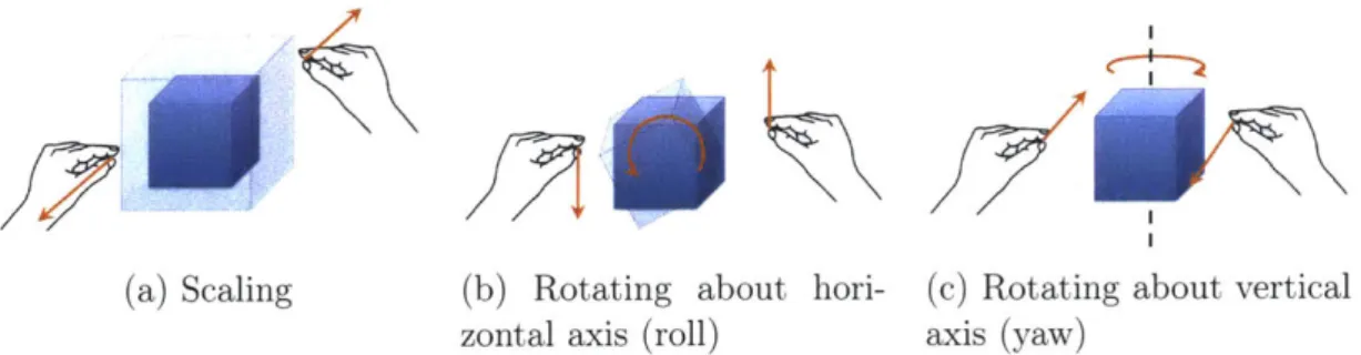
The on-orbit inspection task also allowed for scaling, rotating and repositioning of the simulation environment, to allow the user to change their view of the space station throughout the task. Repositioning of the simulation is achieved through a single-handed tap-and-drag gesture. Scaling and rotating requires two-handed manipulation. Both hands are placed in the ready gesture and then tapped and held. Moving closer/further apart scales the hologram. Moving hands in opposite directions rotates the object in the horizontal (Figure 2-3b) and vertical (Figure 2-3c) directions.
2.2.3
Simulation Environment
The simulation environment for the HoloLens was built using the Unity 3D Gaming
Engine and Microsoft Mixed Reality Toolkit and compiled in Microsoft Visual Studio
~1
(a) Scaling (b) Rotating about hori- (c) Rotating about vertical zontal axis (roll) axis (yaw)
Figure 2-3: Two-handed gestural controls for HoloLens. Note that rotation works best in the yaw and roll directions. Due to the reduced height of the gesture frame,
HoloLens struggles to detect rotation in the pitch direction.
2017. Unity is a cross-platform gaming engine that supports the creation of 2D, 3D,
VR, and AR games and simulations. Unity offers a primary scripting API in C#, as
well as the importation of 3D models from computer graphics programs like Blender.
Unity provides the framework for game development, allowing the importing of assets
(models, characters, audio, textures), assembly of these assets into scenes, and the
ability to add physics models, interactivity, and gameplay logic. The core building blocks of Unity games are Game Objects, empty containers into which lighting and audio components, scripts, and objects for the scene are placed.
Unity uses a concept called Parenting to organise the Game Objects. Game Ob-jects are organised into a hierarchy which constitute a scene for your game. The top most game object is the Parent Game Object, and all objects grouped under-neath it are Child Objects. Child Objects inherit the movement and rotation of the Parent Game Object. Figure 2-4 shows the hierarchy of the on-orbit inspec-tion simulainspec-tion developed for this thesis. A number of Game Objects are from the Microsoft Mixed Reality Toolkit, a GitHub repository of scripts and assets de-veloped by Microsoft and other developers specifically for use with the HoloLens.
ing HoloLens simulations, placing a camera within the game at the location of the HoloLens user's head. InputManager is the HoloLens Object which organises all gestural, verbal and gaze input that is detected, and Def aultCursor provides the cursor users see within the HoloLens that lets them interact with the simulation. DirectionalLight is the default Light Object within Unity to illuminate the scene, as holograms would not be lit by ambient light within the room.
The remainder of the Game Objects were custom built for this simulation and will be discussed in the subsequent sections. The primary Parent Objects are the newISSmodules2, which contains the simulation environment, and ControlPad, which contains the user interface for controlling the inspector.
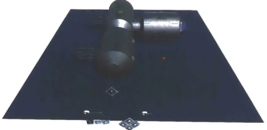
The simulation environment was designed to simulate an on-orbit inspection task of a space station. The environment consisted of a space station model, a floor sur-face, an inspector satellite, a control pad, and a waypoint (if active). Figure 2-5 depicts the holographic environment. It should be noted that all distance measure-ments given regarding the simulation and the results of the simulation are given in Unity unit measurements. In Unity simulations, 1 Unity unit typically corresponds to 1 meter, however HoloLens simulations allow scaling of objects and thus distance units are subject to change. For this study, all distance were measured relative to the world frame of the space station and units scale when objects are scaled, so relative distances between objects were maintained even under scaled conditions.
Space Station
The space station model was constructed in the Blender computer graphics pro-gram and imported into Unity. To address aspects of environmental risk outlined in Research Question 2, the design of the space station incorporated various
ge-V Q Experiment* 0 MixedRealityCameraParent 0 InputManager 1 DefaultCursor Directional Light V newlSSmodules2 I Station iFloor V SPHERES +CollisionDetector *;(WaypointMarker CritDebrislmpactSiteHigh W NonCritDebrisImpactSite CritDebrisImpactSiteLow T ControlPad qWaypointToggle V ,iWaypointButtons 0 MakeWaypoint * SetWaypoint 0DeleteWaypoint *VPanLeftButton 1 PanRightButton V DPad 6 FrameToggle V LocalDPad 0 ForwardButton %BackwardButton %RightButton LeftButton PanLeftButton W PanRightButton V i GobalDPad SForwardButton - BackwardButton WRightButton LeftButton *tPanLeftButton tPanRightButton LogAnomaly Logger TimeOut
Figure 2-4: Hierarchy of Game Objects for on-orbit inspection simulation. Drop-down arrows have been used to show the key Parent and Child Objects used in the simulation.
Figure 2-5: Simulation environment within Unity. The inspector is shown in red. The space station, floor, and control pad are shown.
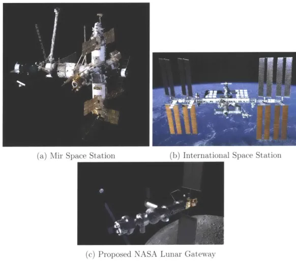
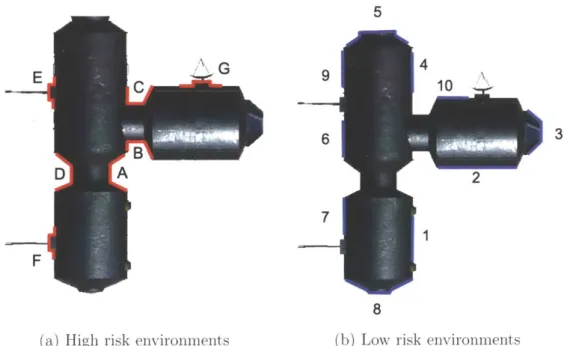
ometries, classified as either high or low risk. Inspiration was drawn from existing and previous space stations designs (Figure 2-6) in the design of the station and these risk areas. High risk areas were areas of limited clearance for the inspector and required increased localization to inspect the region of interest, such as highly concave geometries (e.g. nodes between connecting modules), high vertex objects (e.g. complex attachments on the station like communication dishes), and protru-sions (e.g. solar panels). Low risk areas were areas with flat or convex geometries, or limited vertices (e.g. the surface of a module). The final station model is shown in Figure 2-7. The station is comprised of two modules joined parallel, and a third module perpendicularly attached. These modules are modelled after the Harmony and Columbus modules onboard the ISS. Two solar panels and a communication dish are attached to the exterior, and a cupola is attached to the end of one module. Figure 2-8 highlights the areas of high and low risk around the station model.
In order to detect when the inspector satellite collided with the station, colliders needed to be implemented on the station model. Colliders are invisible objects
(a) Mir Space Station (b) International Space Station
(c) Proposed NASA Lunar Gateway
Figure 2-6: Previous, current and future space stations.
(a) Forward isometric view
Figure 2-7: Final space station model constructed in Blender.
5 A G 9 E F 6 7 8
(a) High risk environments (b) Low risk environments
Figure 2-8: Location of high and low risk environments around the exterior of the space station. High risk areas are labelled with letters, low risk areas are labelled with numbers.
3 (b) Aft isometric view
Figure 2-9: Colliders used for the space station model in Unity. Colliders are shown as green transparent shapes.
described by mathematical equations which are used to detect physical collisions between objects within the environment. The least-processor intensive colliders are
primitive colliders; box (rectangular prisms), sphere, and capsule (two hemispheres
and a cylinder). Mesh colliders can be used to exactly match the contours of a given object, however thiey are more computationally intensive and cannot be used to collide with other mesh colliders. For the on-orbit inspection simulation, the space station was approximated by a number of box and capsule colliders (see Figure 2-9). The inspector collision detection will be discussed below.
Users were able to move, scale and rotate the space station (and all Child Ob-jects), using the HoloLens two-handed gesture commands. The HoloLens script TwoHandManipulatable. cs (available from the Mixed Reality Toolkit) is attached to the space station Game Object in order to make it interactable with two-handed
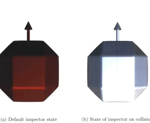
(a) Default inspector state (b) State of inspector on collision
Figure 2-10: Inspector satellite model in Unity.
and for specific functions (moving, scaling, rotating). For this simulation, two-hand manipulation was restricted to scaling and rotating with no axis restrictions.
Inspector Satellite
The inspector satellite simulation model was originally designed for the hardware ex-perimental tests, and as such is modelled off the SPHERES platform. The inspector model was also built in Blender, based off the polyhedral design of the SPHERES. The forward facing face of the inspector is identified by an arrow representing the normal vector of this face. The default inspector color is red, to match the SPHERES satellite (Figure 2-10a).
As would be the case with the ground-based SPHERES platform, the inspector is restricted to motion in the X-Y plane, and rotations about its vertical Z-axis.
The inspector satellite object (SPHERES) is a child of the station object (Station), and consequently whenever the station is scaled, rotated, or repositioned by the operator, the inspector moves with it, maintaining its relative position. The inspector is controlled via the control pad, which is discussed in Section 2.2.4. When the inspector collides with the station object, it changes color to white to indicate a collision (Figure 2-10b). Unity uses in-built trigger functions OnCollisionEnter and OnCollisionExit to determine when an object interacts with a collider. A code containing these functions is attached to the inspector object and whenever the inspector interacts with the station collider, this triggers the above functions, records the collision, and changes the color of the inspector.
2.2.4
Command Modes for Inspector
The inspector is controlled by the user via the ControlPad Game Object, which is decomposed into 3 methods of command; Waypoint Mode, Global Mode and Local Mode. The control pad is composed of holographic buttons that register single taps from the user which translate to commands for the inspector. Buttons for a single command mode are visible at one time, and users can switch between command modes by tapping the frame toggles in the uppermost left and right corners of the control pad. While the station object can be repositioned by the user, the control pad remains fixed in the world frame, only rotating about its axis to ensure it always faces the user if they move slightly.
Waypoint Command Mode
Waypointing is a high-level method of commanding robots that uses intermediate target points along a route as goal states for the robot. These waypoint target points
specify a high-level state (usually position coordinates and orientation), rather than dictating the precise control movements a robot must follow. The SPHERES robots use waypoints as a means of navigation. Within the on-orbit inspection simulation, the Waypoint control pad is used for the various functions within the Waypoint Mode (Figure 2-11). Once active, waypoints appear as red flags in the simulation (Figure 2-12). The Waypoint system is based off the SPHERES robot, which can only send data packets containing one waypoint at a time, therefore within the simulation only one waypoint can be active at once. Another waypoint cannot be placed until the inspector has reached the current waypoint, at which point the current waypoint deletes.
The Waypoint Mode has 4 different command functions
" Generate - Waypoints are not always active in the simulation, they must be
generated. The Generate button on the waypoint control pad spawns a flag marker at the location of the inspector at the beginning of the simulation. Waypoints always spawn in the same position.
" Move - Once a waypoint is generated, it can be moved around the simulation to the desire location by tapping and dragging the flag marker.
* Set - Once the user is satisfied with the position of the flag marker as a target position for the inspector, the waypoint must be set by tapping on the Set button. This commands the inspector to move towards this waypoint. The waypoint will disappear once the inspector reaches its location.
* Delete - A currently active waypoint can be deleted by pressing the Delete
button. Delete can be used prior to the Set function if the user loses the waypoint, or whilst the inspector is en route to the waypoint. If the inspector
ypontOn
Figure 2-11: Control pad in Waypoint Mode. The toggle in the upper left indicates
that Waypoint Mode is switched on.
I
Figure 2-12: Waypoint marker as it appears in the simulation
is en route when a waypoint is deleted, the inspector will stop at its current position.
The Pan Left and Pan Right buttons rotate the inspector ±15° about its vertical axis. The inspector moves in a straight line from waypoint to waypoint at a fixed speed of 1 Unity unit per second. No path planning algorithm has been incorporated
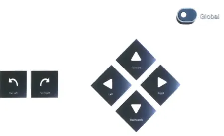
Global Command Mode
The Global Command Mode is a low-level command mode that commands the in-spector to move in specific directions and orientations, rather than giving it target locations. Commands in the Global Command Mode are given relative to the Global World Frame of the space station (Figure 2-13). Directional command is achieved by tapping on one of the directional pad buttons, and rotational command is achieved
by tapping the panning buttons, as described below:
• Forward: +Y
" Backward: -Y
* Right: +X " Left:
-X
• Pan Right: +Z rotation
•
Pan Left: -Z rotationHolographic buttons could not be scripted to respond to a tap-and-hold, therefore only single taps on buttons could be implemented. Thus the Global Command Mode has discrete, rather than continuous, control. Each directional movement moves the inspector 0.2 Unity units, and each rotation movement rotates the inspector 15.
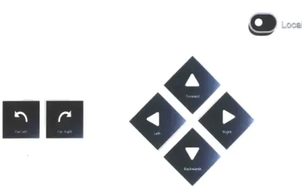
Local Command Mode
The Local Command Mode is operated in an identical manner to the Global Com-mand Mode, but moves the inspector relative to its own local body frame (Figure
Figure 2-13: Global world frame of the space station, used for Global Command Mode. Note that the
+
Z axis points up out of the page.Figure 2-14: Control pad in Global Mode. The toggle in the upper right indicates that Global Mode is switched on.
![Figure 2-2: HoloLens user interactions [43]](https://thumb-eu.123doks.com/thumbv2/123doknet/14380913.506102/34.917.188.759.66.514/figure-hololens-user-interactions.webp)