HAL Id: hal-01877594
https://hal.archives-ouvertes.fr/hal-01877594
Submitted on 20 Sep 2018
HAL is a multi-disciplinary open access
archive for the deposit and dissemination of
sci-entific research documents, whether they are
pub-lished or not. The documents may come from
teaching and research institutions in France or
abroad, or from public or private research centers.
L’archive ouverte pluridisciplinaire HAL, est
destinée au dépôt et à la diffusion de documents
scientifiques de niveau recherche, publiés ou non,
émanant des établissements d’enseignement et de
recherche français ou étrangers, des laboratoires
publics ou privés.
Injection System Design Impact on the Stabilization and
Acoustic Response of Premixed Swirling Flames
M. Gatti, R Gaudron, Clement Mirat, Thierry Schuller
To cite this version:
M. Gatti, R Gaudron, Clement Mirat, Thierry Schuller. Injection System Design Impact on the
Stabilization and Acoustic Response of Premixed Swirling Flames. 8th European Combustion Meeting
2017, Apr 2017, Dubrovnik, Croatia. �hal-01877594�
Injection System Design Impact on the Stabilization
and Acoustic Response of Premixed Swirling Flames
M. Gatti
a,∗, R. Gaudron
a, C. Mirat
a, T. Schuller
aaLaboratoire EM2C, CNRS, CentraleSup´elec, Universit´e Paris-Saclay, 92295 Chˆatenay-Malabry cedex, France
Abstract
This article reports a series of experiments on the stabilization and acoustic response of swirling lean premixed methane/air flames when the injector system design is modified. The design modifications comprise changes of (1) the main dimensions of a radial swirler, (2) the diameter of the injection nozzle, (3) the diameter of a cone used as a bluff body and (4) the distance L between the swirler and the injector nozzle outlet. In agreement with previous observations, the FTF of these swirling-flames features a drop of the gain in a frequency range that depends on the bulk flow velocity and on the distance L. As the swirl number increases, the difference between FTF gain extrema is found to increase as well, a feature which is more evident when the flow passage area is increased, compared to when the swirler geometry is optimized. It is concluded that, even if the FTF gain decreases for increasing swirl levels, a compromise needs to be found between flame stabilization and acoustic response optimization, since an excessive swirl level could result in flame flashback.
Introduction
In many industrial devices lean-premixed flames are stabilized by a swirling flow. This mode of opera-tion allows lowering pollutant emission levels with more compact flames, thus increasing the power-density ratio, but raises combustion dynamics problems, most impor-tantly flashback, blow-off and thermo-acoustic instabili-ties [1, 2,3]. An accurate description of the flame re-sponse to incident perturbations is necessary for the pre-diction of combustion instabilities. In fully premixed sys-tems, this response is generally characterized by a trans-fer function between heat release rate fluctuations ˙Q0and
harmonic velocity disturbances u0that produce them [4]:
F ( f )= Q˙
0/ ˙Q
u0/u =G( f ) exp(iϕ( f )) (1)
where G and ϕ denote the gain and phase lag of the Flame Transfer Function F (FTF), which are functions of the forcing frequency f and the forcing level as well [5].
Many recent investigations of the FTF of swirling flames by modeling approaches [8,9,10], numerical sim-ulations [11,12] and by experimental means [2,7,13] indicate that the injector dynamics and the response of the swirler to flow perturbations need to be considered to interpret the main features of the FTF of swirling flames. Due to the diverging streamlines of a swirling jet flow, Hirsch et al. [8] found that the azimuthal vorticity is fluc-tuating resulting in a modulation of the swirling strength in the flow downstream the injector nozzle. Komarek and Polifke [13] found that the FTF of swirl-stabilized lean premixed flames feature a large drop of the FTF gain in the intermediate frequency range and that the frequency corresponding to this minimum gain value is a function of the distance between the swirler and the injector out-let. They showed by numerical simulations that this
phe-∗
Corresponding author: marco.gatti@centralesupelec.fr Proceedings of the European Combustion Meeting 2017
nomenon is due to swirl number oscillations that are gen-erated at the swirler outlet and are then convected by the mean flow. In a series of work, Palies et al. [7,11,14] fully interpret this mechanism and demonstrate that az-imuthal waves are generated at the swirler trailing edge when the swirling vane is impinged by axial acoustic waves. These two waves lead to different responses of the swirling flame and their interference leads to an out of phase motion of the flame base with respect to the flame tip. Models were proposed for these mechanisms and the resulting flame wrinkling process [7,9]. The net effect is that large swirl number oscillations at the burner outlet lead to a low FTF gain due to a balance of heat release rate oscillations produced close to the flame root and close to the flame tip [3,11]. Swirl number oscillations mainly al-ter the flame base motion. Larger angular oscillations of the flame position with respect to the main flow direction are observed as the level of swirl number oscillation in-creases. This flame root oscillation mechanism interferes with heat release rate oscillations produced by flame vor-tex rollup at the flame tip. These two contributions to heat release fluctuations are found to be out of phase at the gain minimum. Since the level of swirl number oscil-lations depends on the axial distance from the swirler to the injector outlet, this mechanism depends on frequency. When swirl number oscillations are low, heat release rate oscillations near the flame base and those at the flame tip are nearly in phase leading to a maximum value of the FTF gain.
Swirl number induced flame oscillations interfering with flame tip vortex roll-up have been confirmed by other recent experiments conducted in lean swirling pre-mixed systems [15] as well as with swirling spray di ffu-sion flames [16]. Large swirl number oscillations were also identified in aero-jet swirling injectors with an air-blast atomizer [17]. In this later case, these oscilla-tions were shown to modify the fuel spray dynamics and droplet size distribution. Straub and Richards [18] found
that the location of the axial swirling vane significantly alters the magnitude of the thermoacoustic instabilities observed in their high pressure test rig operated with pre-heated air.
While the mechanisms leading to swirl number os-cillations are now well understood and the frequency at which the largest effects on the FTF is well predicted by considering the time lag of azimuthal wave disturbances convected by the mean flow between the swirler and the injector outlet [7,8,13,15], there is yet no systematic at-tempt to use these swirl number oscillations to minimize the FTF gain.
The objective of this study is to characterize the di ffer-ences between various injection system designs regarding flame stabilization and flame response to acoustic exci-tation. Only fully premixed flames stabilized on radial swirling injectors are considered. Their FTF is deter-mined and the main elements leading to the largest drop of the FTF gain are analyzed with a set of experiments. The design modifications comprise changes of (1) the main dimensions of the radial swirler, (2) the diameter of the injection nozzle, (3) the design of a central bluff body terminated by a cone of variable diameter and (4) the distance between the swirler and the injector nozzle outlet.
The article is organized as follows. The experimen-tal setup is presented in the next section. The flows and flames are then examined at steady injection conditions. The analysis of the FTF data obtained for the different in-jectors is presented next. Conclusions are drawn regard-ing stabilization and acoustic response properties of the various injector geometries.
Experimental setup
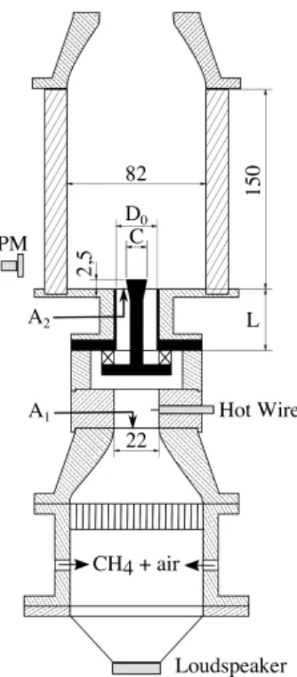
In the burner sketched in Fig.1, a mixture of methane and air is injected from two diametrically opposed aper-tures positioned at its base. The flow crosses a grid and a honeycomb to break the largest turbulent scales. A con-vergent section produces a top-hat velocity profile at the location where the flow velocity is measured with a hot-wire anenometer probe (Dantec Dynamics - Probe 55P16 with a mini-CTA 54T30). The diameter of this section is D= 22 mm. The cross section area at this location, which is constant for all the configurations tested in this study, is designated as A1. A radial swirler with tangential inlets
is fixed in an enlarged section. It consists of 6 cylindrical inlets of variable diameter Dsas sketched in Fig.2. The
distance between the axes of two diametrically opposed inlets is 2H. The flow leaves the swirler into a central injection tube. The diameter D0of this tube can be
mod-ified. A central rod of diameter d = 6 mm ending with a cone of variable diameter C at the top is inserted in the injection tube to ease stabilization. The cross section area A2at the injector outlet changes in the various
configura-tions. The chamber, made of 4 transparents quartz win-dows, has a squared cross-section of 82 mm width and 150 mm length. At the base of the burner, a loudspeaker (Monacor SP-6/108PRO, 100 Watts RMS) is mounted to pulsate the flow. The velocity oscillations are
mea-D0 C 82
2,5
150
Figure 1: Burner sketch. The main dimensions are indi-cated in millimeters.
Swirler 2: Ds=6 mm, H=6 mm
Swirler 3: Ds=5.6 mm, H=4.5 mm
Swirler 4: Ds=5.6 mm, H=3.5 mm
Figure 2: Swirler geometries.
sured with the hot-wire. A photomultiplier (Hamamatsu, H5784-04), equipped with an OH* filter (Asahi Spectra, ZBPA310) center around 310 nm, is used to measure the heat release rate fluctuations. The setup was designed to easily allow the substitution of some of the components and analyze effects of geometrical modifications on flame dynamics. The replaceable components are represented in black in Fig.1. Three different swirlers are tested, des-ignated as swirler 2, 3 and 4 in Fig.2, with three diam-eters of the central injection tube: D0 = 22 mm, 20 mm
and 18 mm. The size of the end cone at the top of the central insert is modified: C = 10 mm, 12 mm, 14 mm, as well as the distance L between the swirler and the in-jector exit plane. The equivalence ratio φ= 0.82 and the bulk velocity Ub = 5.44 m/s at the hot-wire location
de-duced from the air and methane mass flowrate indications (at 20oC and p= 1 atm) are fixed for all the experiments
conducted in this study. The system is thus operated at a constant thermal power P = 5.44 kW assuming total combustion.
Laser Doppler Velocimetry is used to analyze the flow at the injector outlet. The flow is in this case seeded with small oil droplets of 3 µm. An intensified CCD cam-era (Princeton Instruments, PI-MAX 4, 1024×1024
Table 1: Configurations explored. Swirler design: D0: injection tube diameter, C: conical end piece diameter, L :
distance between the swirler and injection plane outlet, A1/A2: normalized injector cross section area. S∗: Estimated
swirl number. S : Swirl number deduced from LDV measurements.
Case Swirler D0[mm] C[mm] L[mm] A1/A2[-] S [-] A 2 20 10 49 4.00 0.77* B 2 20 12 49 5.26 0.73 C 2 20 14 49 7.69 0.64* D 2 18 12 49 8.33 0.62* E 2 20 10 39 4.00 0.77* F 2 22 10 49 2.86 0.86* G 3 22 10 49 2.86 0.84* H 4 22 10 49 2.86 0.75* I 2 22 12 49 3.70 0.81 J 3 22 12 49 3.70 0.79 K 4 22 12 49 3.70 0.71 L 3 18 12 49 8.33 0.59 M 4 18 12 49 8.33 0.54* N 3 20 10 49 4.00 0.73 O 3 20 12 49 5.26 0.69 P 3 20 14 49 7.69 0.61 Q 4 20 12 49 5.26 0.63 R 2 18 14 49 12.5 0.55* S 3 18 14 49 12.5 0.52* T 4 18 14 49 12.5 0.48*
els) mounted with an UV objective and equipped with the same filter as the photomultiplier is used to record the OH* emission from the flames under steady injection conditions. -2 -1 0 1 2
r/R
0[-]
-15 -10 -5 0 5 10 15u
[m
/s
]
R
0[-]
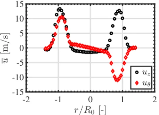
u [] uz uθFigure 3: Mean axial uz and azimuthal uθvelocity
com-ponents for Swirler 2, D0 = 20 mm and C = 12 mm.
Case B in Tab.1.
Steady Flow and Flame Analysis
It is known that the swirl number controls the stabi-lization of swirling flames and that changes in this quan-tity have an important impact on the flame dynamics. The swirl number is first measured for Swirler 2 (Fig.2) and for an injection tube of diameter D0 = 20 mm with a
cone of C = 12 mm diameter when the system is
oper-ated without combustion and without flame tube. Laser Doppler Velocimetry measurements of the axial uz and
azimuthal uθvelocity components are carried out. Mea-surements are made 4 mm above the injector outlet, i.e. 1.5 mm above the top cone of the central bluff-body, with a resolution of 0.5 mm along the radial direction.
Results are presented in Fig.3. The axial velocity pro-file uzfeatures a central recirculation zone with negative
velocities and the azimuthal velocity uθ has a Rankine
like shape profile in the center part of the flow. The swirl number S of this injector is deduced from:
S = 1 R0 R uθuzr2dr R u2 zrdr (2)
where R0 = D0/2. One finds for this case S = 0.73, a
value typical of many injectors used to stabilize swirling flames.
The same measurements were repeated for a set of geometrical configurations (Tab.1). One can see that the swirl number decreases from swirler 2 to 4 when D0and
Care kept constant. For a fixed swirler design, the swirl number S increases if the injection nozzle diameter D0
increases or if the diameter C of the conical end piece de-creases, i.e. when the flow passage area A2/A1increases.
For the remaining configurations, an analytical expres-sion is used to estimate the swirl number S∗by assuming a uniform axial flow profile and a linear profile for the azimuthal velocity component.
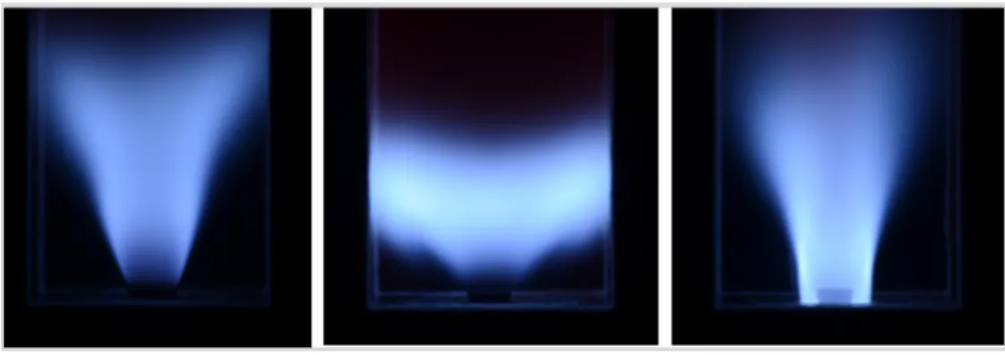
ffer-Figure 4: Swirl number effect on flame stabilization. (a) S =0.48, case T, elongated flame close to blow off. (b) S =0.73, case B, well-stabilized flame. (c) S=0.86, case F, flash back. See Tab.1for the different cases tested.
0.3 0.4 0.5 0.6 0.7 0.8 0.9 1 0 5 10 15
R
u
Flashback Elongated Flames Well-Stabilized FlamesA
1
/A
2
[-]
S [-]
Figure 5: Stabilization chart plotting different flame regimes as a function of the normalized flow passage area ratio A1/A2and the swirl number S
ent injectors tested. Three stabilization modes are iden-tified depending on the value of the swirl number S and the normalized injector nozzle cross section area A1/A2.
These three regimes are presented in Fig.4. Close to blow off, when the swirl number is too low the flame is elon-gated in the downstream direction and cannot be assumed to be compact as in the left image. In the middle image, when the swirl number is high enough the flame is well stabilized and has a compact shape. In the right image, when the swirl level is too high flash back takes place and the flames protrudes inside the injector. The stabilization chart in Fig.5delineates the different regimes observed
for the injectors tested in Tab.1. When the swirl number is between 0.5 and 0.8, flames are well-stabilized. When S > 0.84, flashback inside the injector occurs. When S < 0.5, the shape of the flame becomes elongated and one approaches the blow off limit. These critical bound-aries also depend on the ratio A1/A2.
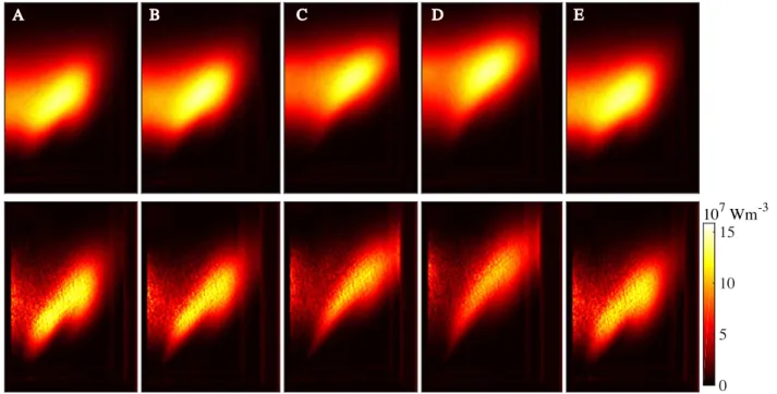
OH* images of the mean turbulent flame structure, de-duced by averaging a hundred snapshots recorded with the ICCD camera with a long exposure time, are shown
in Fig. 6. As the swirl number indicated in Tab. 1 re-duces, the flame becomes more elongated, moves further away from the injector outlet and closer to the chamber walls. Changing the distance L does not lead to modifica-tion of the mean flame structure (cases A and E in Fig.6), since the swirl number does not depend on this distance. Images in the bottom of Fig.6show the OH* flame lu-minosity in a longitudinal plane crossing the burner axis after Abel transformation. These latter images give an in-dication of the distribution of heat release rate in W m−3.
Flame Transfer Function
The FTF is determined from Eq. (1) by submitting the flame to harmonic modulations of the flowrate. The ve-locity fluctuation u0is controlled with the hot wire. This
probe is located in the nozzle of the convergent piece in Fig.1. It has been checked that the velocity has a top hat profile with a low level of turbulence at this location. The photomultiplier with the OH* filter is used to determine the mean ¯I and fluctuating I0luminosity signals integrated
over the flame volume and over the line of sight. These signals are assumed to be a good tracer of the heat release rate for the lean premixed flames investigated. The trans-fer function is deduced from the cross and power-spectral densities between the photomultiplier and hot wire sig-nals examined at the forcing frequency f . These sigsig-nals are recorded at a sampling rate of fs = 8192 Hz over
4 seconds and Welch periodograms are used to obtain sta-tistically converged results.
FTF data are presented in Fig.7for the flames inves-tigated in Fig.6. Data are plotted in the frequency range 40-210 Hz for a velocity perturbation level u0/u = 0.10,
where u and u0 denote the mean and root-mean-square
values of the signal measured by the hot wire. The shape of these FTF is very similar to that found by Palies et al. [7] and in many other studies. The gain first increases with the frequency to reach a maximum. This maximum gain value does not seem to depend much on the swirl number or on the geometrical configuration of the injector tested. The gain curve then features a sudden drop with a valley and reaches a minimum value at a frequency which changes with the geometry of the tested injector. This
A B C D E 0 5 10 15 107Wm-3
Figure 6: Flame shapes for cases A to E in Tab.1.
0 0.5 1 1.5 2 G [-] 0 50 100 150 200 250 f [Hz] 0 π/2 π 3π/2 ϕ [r ad ] R0 [-] u [] A B C D E
Figure 7: FTF of the flames explored in Fig.6obtained with swirler 2.
quency also corresponds to an inflection point in the FTF phase plot. The value reached by the gain also depends on the geometrical configuration tested. At higher fre-quencies, the FTF gain increases again to reach a second maximum.
Most of these features were already described in [7,19]. The drop of the FTF gain in the intermediate fre-quency range is associated to swirl number oscillations that were shown to lead to large heat release rate dis-turbances at the flame bottom that destructively interfere with those acting at the flame tip and which are associated to flame-vortex roll-up [3]. It was shown by Komarek
and Polifke [13] that the frequency at which the FTF gain is the lowest is controlled by the distance between the swirler and the injector outlet. This is highlighted in Fig.7by comparing cases A and E. The FTF gain curve is globally shifted to higher frequencies and the minimum moves from f = 120 Hz (case A) to f = 140 Hz (case E) when the swirler to the nozzle outlet distance is reduced from L= 49 mm to L = 39 mm.
One interesting feature which has not been fully de-scribed yet is that the minimum gain value reached by the FTF decreases as the swirl number increases. Minimizing the FTF gain of premixed swirling flames by controlling the swirl level has recently been addressed in [20]. Com-plementary observations are made here. For a fixed injec-tion nozzle diameter D0, the FTF gain minimum slightly
reduces as the swirler design is optimized to increase the swirl number. However, increasing the flow passage area A2, either by increasing the nozzle outlet diameter D0or
by decreasing the bluff-body end cone diameter C, has a larger impact on the FTF than optimizing the swirler de-sign. As the flow passage area increases, the difference between the maximum and the minimum values of the FTF gain is found to increase as well in Fig.7.
Another interesting feature may be pointed out. The deformation of the shape of the FTF phase lag evolu-tion in the region where the FTF gain reaches a minimum value is directly linked to the minimum value of the FTF gain. Only a small changes of the FTF phase lag is seen for flames B, C and D close to the inflection point of the curve, while phase excursions of more than π/4 and close to π/2 are observed for flames A and E respectively close to the same regions.
Conclusion
Experiments were carried out to investigate changes in the stabilization properties and in the acoustic re-sponse of swirl-stabilized lean premixed methane/air flames when the system is operated at constant equiva-lence ratio φ = 0.82 and constant thermal power P = 5.44 kW with different injectors. Three radial swirling vanes with cylindrical injection holes yielding an increas-ing level of swirl were tested. Effects of a reduction of the diameter of the injection tube and of the size of a conical end-piece used as a central bluff-body were investigated. A modification of the distance between the swirler and the injector outlet was also analyzed for one selected con-figuration.
It is found that the FTF of these swirling-flames fea-tures a drop of the gain in the intermediate frequency range. The frequency corresponding to this minimum shifts to lower values as the bulk flow velocity decreases at the nozzle outlet or as the distance between the swirler and the injector exit plate increases. These observations are in agreement with previous analysis of the response of swirling flames. A focus is then made on effects leading to the largest drop of the FTF gain at this forcing fre-quency. The main findings are: (1) the biggest difference between FTF gain extrema is obtained for the swirler fea-turing the highest swirl number, (2) increasing the flow passage area, by increasing the diameter of the nozzle outlet or by reducing the size of the conical end piece serving as a bluff-body leads to increased swirl levels and to further reduction of the FTF gain minimum, and (3) a compromise needs to be found between flame stabiliza-tion and optimizastabiliza-tion of its acoustic response. The largest swirl levels lead to the lowest FTF gain values, but too large swirl levels lead to flashback of the flame inside the injector.
Acknowledgements
This project has received funding from the Euro-pean Union’s Horizon 2020 research and innovation pro-gramme under the Marie Sklodowska-Curie grant agree-ment No 643134. This work is supported by Agence Na-tionale de la Recherche, NOISEDYN project (ANR-14-CE35-0025-01). The authors are thankful to the techni-cal staff of EM2C laboratory for their assistance during the design and construction of the experimental setup. References
[1] Lieuwen, T. C., and Yang, V., eds., 2005. Combustion instabili-ties in gas turbines, Operational experience, Fundamental mech-anisms, and Modeling, Vol. 210 of Progress in Astronautics and Aeronautics. American Institute of Aeronautics and Astronautics, Inc.
[2] Huang, Y., and Yang, V., 2009. “Dynamics and stability of lean-premixed swirl-stabilized combustion”. Progress in Energy and Combustion Science, 35(4), pp. 293–384.
[3] Candel, S., Durox, D., Schuller, T., Bourgouin, J.-F., and Moeck, J., 2014. “Dynamics of swirling flames”. Annual Review of Fluid Mechanics, 46, pp. 147-173.
[4] Ducruix, S., Schuller, T., Durox, D., and Candel, S., 2003. “Com-bustion dynamics and instabilities: Elementary coupling and driv-ing mechanisms”. Journal of Propulsion and Power, 19(5), pp. 722–734.
[5] Noiray, N., Durox, D., Schuller, T., and Candel, S., 2008. “A unified framework for nonlinear combustion instability analysis based on the flame describing function”. Journal of Fluid Me-chanics, 615, pp. 139-167.
[6] Cosic, B., Terhaar, S., Moeck, J., and Paschereit, C., 2015. “Re-sponse of a swirl-stabilized flame to simultaneous perturbations in equivalence ratio and velocity at high oscillation amplitudes”. Combustion and Flame, 162, pp. 1046-1062.
[7] Palies, P., Durox, D., Schuller, T., and Candel, S., 2010. “The combined dynamics of swirler and turbulent premixed swirling flames”. Combustion and Flame, 157, pp. 1698–1717. [8] Hirsch, C., Fanaca, D., Alemela, R., Polifke, W., and Sattelmayer,
T., 2005. “Influence of the swirler design on the flame trans-fer function of premixed flames”. In ASME Turbo Expo 2005, no. GT2005-68195, ASME 2005 Gas Turbine Technical Congress & Exposition.
[9] Palies, P., Schuller, T., Durox, D., and Candel, S., 2011. “Mod-eling of swirling flames transfer functions”. Proceedings of the Combustion Institute, 33, pp. 2967–2974.
[10] Acharya, V., Shreekrishna, Shin, D., and Lieuwen, T., 2012. “Swirl effects on harmonically excited, premixed flame kinemat-ics”. Combustion and Flame, 159, pp. 1139–1150.
[11] Palies, P., Schuller, T., Durox, D., Gicquel, L., and Candel, S., 2011. “Acoustically perturbed turbulent premixed swirling flames”. Physics of Fluids, 23(037101), 15 pages.
[12] Acharya, V., and Lieuwen, T., 2015. “Effects of azimuthal flow fluctuations on flow and flame dynamics of axisymmetric swirling flames”. Physics of Fluids, 27(105106), 17 pages.
[13] Komarek, T., and Polifke, W., 2010. “Impact of swirl fluctuations on the flame response of a perfectly premixed swirl burner”. Jour-nal of Engineering for Gas Turbine and Power, 132(061503), 7 pages.
[14] Palies, P., Durox, D., Schuller, T., and Candel, S., 2011. “Acoustic-convective mode conversion in an airfoil cascade”. Journal of Fluid Mechanics, 672, pp. 545–569.
[15] Bunce, N., Quay, B., and Santavicca, D., 2014. “Interaction be-tween swirl number fluctuations and vortex shedding in a single-nozzle turbulent swirling fully-premixed combustor”. Journal of Engineering for Gas Turbine and Power, 136(021503), 11 pages. [16] Mirat, C., Durox, D., and Schuller, T., 2015. “Stability analysis of a swirled spray combustor based on flame describing function”. Proceedings of the Combustion Institute, 35, pp. 3291-3298. [17] Giuliani, F., Gajan, P., Diers, O., and Ledoux, M., 2002.
“Influ-ence of pulsed entries on a spray generated by an air- blast injec-tion device: An experimental analysis on combusinjec-tion instability processes in aeroengines”. Proceedings of the Combustion Insti-tute, 29, pp. 91–98.
[18] Straub, D., and Richards, G., 1999. “Effect of axial swirl vane location on combustion dynamics”. In ASME Paper 99-GT-109. [19] Palies, P., Durox, D., Schuller, T., and Candel, S., 2011.
“Experi-mental study on effects of swirler geometry and swirl number on flame describing functions”. Combustion Science and Technology, 183, pp. 704–717.
[20] Gatti, M., Gaudron, R., Mirat, C., Schuller, T., 2017. “Effects of the injector design on the transfer function of premixed swirling flames. ASME TurboExpo, 2017.