Publisher’s version / Version de l'éditeur:
Vous avez des questions? Nous pouvons vous aider. Pour communiquer directement avec un auteur, consultez la
première page de la revue dans laquelle son article a été publié afin de trouver ses coordonnées. Si vous n’arrivez pas à les repérer, communiquez avec nous à [email protected].
Questions? Contact the NRC Publications Archive team at
[email protected]. If you wish to email the authors directly, please see the first page of the publication for their contact information.
https://publications-cnrc.canada.ca/fra/droits
L’accès à ce site Web et l’utilisation de son contenu sont assujettis aux conditions présentées dans le site LISEZ CES CONDITIONS ATTENTIVEMENT AVANT D’UTILISER CE SITE WEB.
Internal Report (National Research Council of Canada. Division of Building
Research), 1971-04-01
READ THESE TERMS AND CONDITIONS CAREFULLY BEFORE USING THIS WEBSITE.
https://nrc-publications.canada.ca/eng/copyright
NRC Publications Archive Record / Notice des Archives des publications du CNRC :
https://nrc-publications.canada.ca/eng/view/object/?id=08582b0f-932f-4ff9-81ad-8482bc5c9fba https://publications-cnrc.canada.ca/fra/voir/objet/?id=08582b0f-932f-4ff9-81ad-8482bc5c9fba
Archives des publications du CNRC
For the publisher’s version, please access the DOI link below./ Pour consulter la version de l’éditeur, utilisez le lien DOI ci-dessous.
https://doi.org/10.4224/20331504
Access and use of this website and the material on it are subject to the Terms and Conditions set forth at
Insulations in a roof system with a protected impermeable membrane
Hedlin, C. P.; Cole, D. G.; Handegord, G. O.
NATIONAL RESEARCH COUNCIL OF CANADA DIVISION OF BUILDING RESEARCH
INSULATIONS IN A ROOF SYSTEM WITH A PROTECTED IMPERMEABLE MEMBRANE
by
C. P. Hedlin, D. G. Cole
and G. O. Handegord
Internal Report No. 388 of the
Division of Building Research
OTTAWA
In 1966, studies were initiated at the Prairie Regional
Station to obtain information about the performance of a new de sign for a flat roof system in which the insulation is placed above the impermeable roof membrane. Because of the nature of the system, the insulation is exposed to conditions that have not been usual for material of this type in the past, and it is important to know how it will perform in terms of physical durability and ability to retain its thermal insulating value.
A number of commonly used building insulations were placed on the deck of a flat roof. Part of each insulation was protected by paving stone cover, part by latex paint, and the remainder was left exposed. This report contains a description of the outside appearance of the insulations and the paint films, as well as the re suIts of
standard thermal conductivity tests made on several of the insulations after three years of exposure. Varying degrees of degradation were observed. The foam plastics showed evidence of erosion where they were not protected from the sun. Some of the insulations buckled, probably due to the combined effects of moisture, temperature change and solar radiation. Others changed very little during the period of test.
Ottawa March 1971
N. B. Hutcheon Director
INSULATIONS IN A ROOF SYSTEM WITH A PROTECTED IMPERMEABLE MEMBRANE
by
C. P. Hedlin, D. G. Cole
and G. O. Handegord
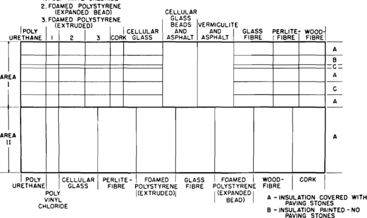
In 1966, an opportunity was provided to observe the performance of a flat roof system having the impermeable membrane protected by
placing it below the insulation. This system consisted of an impermeable
4-ply organic felt membrane on a wood deck, covered by insulation of 2 in. thickness. On one half of the roof (Area II, 10 ft by 47 ft) the
insulation was covered with paving stones. On about three - quarters of
the other half (Area I, also 10 ft by 47 ft) three parallel rows of paving stones wer e placed along the long dimension, leaving two 2 -ft strips
of exposed insulations between them (Figure 1). A 16-in. width of
one of these strips was covered with latex masonry paint, the rest
was fully exposed. The other portion of Area I was covered with
cellular-glass-bead--asphalt and vermiculite--asphalt mixes. Rigid
types of gl a.s s fibre, expanded perlite-fibre, cellular glass, two
types of foamed polystyrene and cork were used. On Area I these
were placed directly on the membrane but not bonded to it. Parts
of Area II incorporated a layer of pea gravel between the insulation and membrane for drainage.
In most properly functioning applications, insulation is not required to meet conditions as demanding as exposure to weather. As a result, some of the insulations failed, and in all cases there was
a change in their physical appearance. Following is a report on
the visual appearance of the insulations and the paint films, on the thermal conductivities of five of the insulations and on a few simple tests of condition after thr ee year s of exposur e.
PHYSICAL APPEARANCE
Polyurethane, where exposed to the sun, buckled resulting in a separation of about 1/2 in. between the insulation and the
membrane. The upper surface eroded as much as 1/4 in. in some
areas. The protective paper, which was originally attached to the
material, almost completely disappeared (Figure 2a). Where
protected by paving stones, it retained its original physical form, with the exception of those edges which were exposed to the elements and which showed the evidence of erosion.
A second polyurethane specimen exposed to the elements also buckled, leaving a gap of about 3 in. between the insulation and the membrane. The unprotected portion of the urethane showed erosion of roughly 1/4 in. (Figure 2b). Where protected by patio stones, the external appearance of the urethane was not much different than that of the original.
A piece of this urethane and a piece of new ur ethane wer e soaked in water over a period of one month. The exposed sample picked up 1100 per cent and the new one 200 per cent moisture by weight, testifying to the existence of internal damage, possibly rupturing of cell walls due to the exposure. Where painted, the urethane was not deformed. There was some evidence of paint cracking but none of blistering or peeling.
Polyvinyl chloride suffered much the same damage as the urethane, buckling so much that it lost all of its insulating value. In this case, however, the buckling occurred with the edges rising and the interior portion remaining substantially in contact with the deck. The upper surface exhibited checking to a depth of
about] /8 in. (Figure 2b). It is more difficult to assess the extent of erosion, since this material does not exhibit the fine-grained structure of the other insulations. The differences in surface level of painted and unpainted areas appeared to be due to shrinkage and cracking of the fully exposed insulation. The plateaus of the
expos ed surface wer e about 1/16 in. below that of the painted surface. Where protected by paving stones, the insulation was substantially unchanged in physical appearance.
The paint film showed no blistering or peeling, and only a small amount of cracking. The painted area deformed only at the edge (where the paint did not protect the insulation); the resulting stresses may have been responsible in part for the paint cracking which occurred within 4 in. of the edge.
The exposed bead-type foamed polystyrene showed no evidence of cracking or separation at the joint between adjacent pieces of the material. The beads wer e clearly delineated since the boundary rn at e r ial of each bead appear ed to be mor e resistant to erosion than the material at its centre. This resulted in a crater -like appearance on the upper surface of the insulation. Each bead formed such a crater with a raised lip and the interior eroded about 1/32 in. below the lip (Figur e 3). The depth of this erosion is shown by the plaster cast in Figure 3 to be about 1/4 in. There was no evidence of discoloration of the material
3
-and its outward appearance was similar to that of undamaged insulation. The paint film did not blister or peel, but did show a number of hairline cracks.
Extruded foamed polystyrene showed neither bending nor shrinkage at the butt joint between the two sections. The original smooth skin of this material eroded away, showing the fine
cellular structure underneath. On the surface of the material there was a thin covering of fine greenish powder, which contained minute scintillating fragments, suggesting that it originated with the insulation itself. Figure 4 shows the plaster cast taken of the painted surface and the adjacent unprotected material. The depth of the erosion is about 1/8 in. The paint film shows no peeling or blistering, and only a few hairline cracks.
The exposed cork insulation lifted 1/4 to 1/8 in. at the edges of the middle portion of the 2 -ft butt joints. There was no evidence of erosion of the cork particles. The only weathering evident occurred as an etching process in which the spaces between particles were leached out so that the particles were set out in strong relief. The paint film did not blister or peel, but there were a number of cracks (Figure 5).
There was evidence of very slight erosion of the cellular glass. Damage had occurred because of the cracking of the material.
In
a number of cases, these cracks ran parallel to and were immediately adjacent to the edge of the paving stone, suggesting that it had been the source of str es s which had resulted in a crack across the section of foamed glass. The paint film was intact, except on areas within about 1 in. of the butt joints, where stresses had resulted in an exfoliation of about 1/8 to 1/4 in. depth, and lifted the paint film as a result. Despite the apparent existence of some stress, the paint film across the butt joint remained intact (Figure 6 ). There was no evidence of the freeze-thaw breakdown at the butt joints described by Malloy (1) .Specimens 2 in. wide and 3/8 in. thick were cut from exposed and unexposed cellular glass. They were used as cantilever beams and loaded to failure within about a minute after the test was started. This was done for both 2 -in. and 4-in. beam lengths. The average calculated breaking stress of the outer fibre of all samples was about 90 psi. The stresses for the exposed samples were about 5 per cent less than for the
unexposed, but the difference is not considered significant because of the small number of samples and the simple measures used in testing. Small amounts of water collected in the material. Samples were crushed and dried, and the amount of moisture found to be about 5 per cent on the dry weight basis.
The glass fibreboard insulation covered a 6-ft by lO-ft area on the roof. It was laid with the vapour barrier side up. There was no physical deformation of the insulation. The exposed vapour barrier material was damaged: some holes appeared in it. The paint peeled and cracked, and some areas of the insulation were expos ed.
There was no evidence of physical deformation of the
expanded perlite -fibr eboar d, and no appar ent erosion or cracking. During much of the time, even in dry weather, this material was damp over a portion of the top, possibly due to wicking of water from below (Figure 7). The paint film was cracked on one of the sections. On the other section it had completely disappeared.
The wood fibreboard insulation showed some delamination. The edges raised about 174 in. and the raised portion extended about 2 or 3 in. in from the edge. The r est of the insulation appeared to be firmly in contact with the deck. There was no evidence of erosion. The paint film peeled over about 5 per cent of the painted area, but the remainder showed no evidence of peeling, blistering or cracking (Figure 8).
The asphalt --foam glas s bead insulation showed a few surface cracks. These did not seem to extend more than 1/2 in. below the surface, and there was no sign of erosion, the upper surface looking much as it did when originally pour ed (Figure 9) .
The expanded vermiculite - -asphalt mix showed a number of surface cracks but they either did not extend to more than 1/4 in. below the surface, or had been filled by movement of the particles into them. There was some erosion of this material and a check indicated that about 1/8 in. of it had been removed since it had been placed (Figure 10).
5
-THERMAL CONDUCTIVITY OF DRIED INSULATIONS
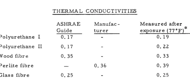
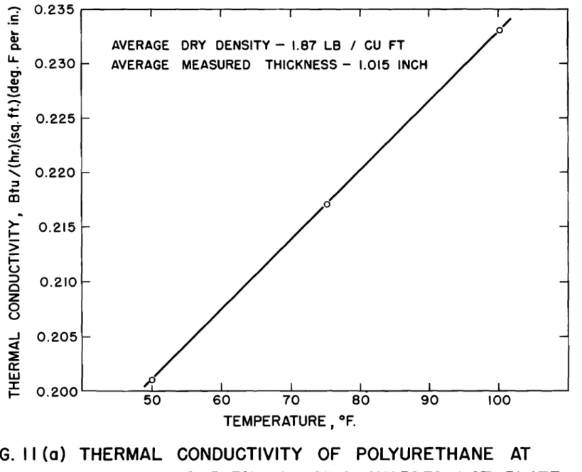
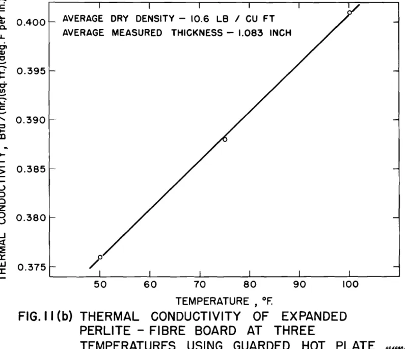
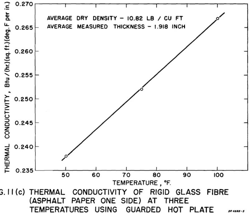
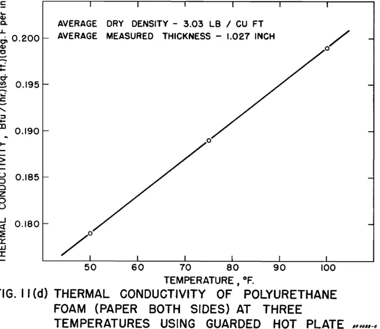
Samples of the two types of polyurethane, the glass fibreboard, the wood fibreboard, and the perlite-fibreboard were taken from under the paving stones, dried, and the thermal conductivity measured
(at Ottawa) (Figure 11). The thermal conductivities of the urethanes
were somewhat higher than for the new materiaL The values for
glass -fi.br e , wood-fibre and perlite insulations were not greatly different than published values for new materials (Table I).
TABLE I THERMAL CONDUCTIVITIES Polyurethane I Polyurethane II Wood fibre Perlite fibr e Glass fibre .,. -r-ASHRAE Guide O. 17 O. 17
0.35
0.25 Manufac-turer0.36
Measur ed after*
exposure (77°F) 0.19 0.22O. 33
0.39 0.25 These thermal conductivities are based on dry condition.During use, the insulations were not generally dry, consequently these values represent a measure of resistance to degradation but not
necessarily of practical performance.
SUMMARY
This report contains observations on the condition of a number of insulations after use above the impermeable membrane of a flat roof
system. There were three degrees of exposure corresponding to
coverage by paving stones, by painting, and bare, unprotected insulation
surfaces. As was expected, varying degrees of physical damage occurred
in the fully exposed materials, ranging from moderate to nearly complete
destruction. The performance of the paint film varied depending on the
type of substrate provided by the insulation. Where the materials were
Several tests were conducted on the materials some of which showed changes from their original characteristics.
The conditions imposed on the insulations were very severe, as they included exposure to moisture, temperature extremes and,
where the insulation was unprotected, solar radiation. The work was
exploratory and the insulations were used in these unique conditions
as one step in the evaluation of this novel roofing system. The results
provide information about the durability and behaviour of the insulations that may be useful in formulating more practical designs.
REFERENCE
1. J. F. Malloy, Thermal Insulation. Van Nostrand Reinhold,
A B C= A C A A PERLITE-I woodセ IFIBRE FIBREI WOOD-
I
CORKI
FIBREA - INSULATION COVERED WITH PAVING STONES
B - INSULATION PAINTED - NO
PAVING STONES
C - FULLY EXPOSED INSULATION GLASS FIBRE I FOAMED
I
POLYSTYRENE I (EXPANDEDI BEAD)PERLITE -
I
FOAMEDI
GLASSFIBRE POLYSTYRENE FIBRE
I(EXTRUDED)I I. POLY VINYL CHLORIDE
2. FOAMED POLYSTYRENE
(EXPANDED BEAD) CELLULAR
3.FOAMED POLYSTYRENE GLASS
I
POLY (EXTRUDED)I
CELLULARI
BEADSAND IVERMICULITEANDURETHANE I I
I
2I
3 ICORK GLASS ASPHALT ASPHALTI
T
AREA Iゥセ
AREA II1
I
POLYI I
CELLULARI
URETHANE GLASS POLY VINYL CHLORIDEFIG.I. ARRANGEMENT OF INSULATIONS IN EXPERIMENTAL FLAT ROOF SYSTEM AS PLACED AUGUST 1966
Erosion of a polyurethane sample. The original protective paper has been lost.
The hole in the centre was made in taking a core sample.
Figure 2b
A second type of polyurethane - bottom half;
polyvinyl chloride - top half. Right side: painted;
Figure 3
Bead-type foamed polystyrene.
Left side: paving stone cover: middle: fully exposed;
right: painted. Plaster cast was made by first laying
down I mil polyethylene.
Figure 4
Cellular foamed polystyrene.
Cork. Left - - painted; right -- fully exposed.
Figure 6
Cellular glass. Bottom -- painted; higher up -- fully exposed;
top - - paving stones. Shows paint induced exfoliation at butt joints and cracking parallel to edge of paving stone.
Figure 7
Expanded perlite-fibre -- middle (arrows).
Dark area is due to moisture. Two sections
of wood fibre lie beyond the perlite.
Figure 8
Wood fibre. Painted -- bottom; fully exposed -- middle;
Foam glass bead- -asphalt mix.
Figure 10
-:-
0.235
セ
Oo23J
_0/
AVERAGE DRY DENSITY -
I. 87 LB / CU FT
AVERAGE
MEASURED
THICKNESS -
1.015 INCH
0' Q) セ
-
セ -セ0.225
C" fJ)--
セ .s:::.-
<,0.220
:::J-rn
..
>
0.215
....
>
....
u
::>
0.210
0 Z 0 U -l0.205
<X
:E
a::
w
0.200 1
セ セ I....
50
60
70
80
90
100
TEMPERATURE,
oF.
FIG. II (a) THERMAL CONDUCTIVITY OF POLYURETHANE
AT
THREE TEMPERATURES USING GUARDED HOT PLATE
8R4868-4
100
90
60
50
/0
AVERAGE DRY DENSITY - 10.6 LB / CU FT
AVERAGE MEASURED
THICKNESS -
1.083 INCH
70
80
TEMPERATURE ,
oF.
FIG.
II
(b) THERMAL
CONDUCTIVITY
OF
EXPANDED
PERLITE - FIBRE BOARD AT
THREE
TEMPERATURES USING GUARDED
HOT PLATE
...J <3: セ
a::
セ
0.375
....
セ セ0.400
u, c:..
>-....
>
0.385
....
u
::::>
£:)z
8
0.380
-.
C'eu
"'C-
:?
0.395
-
ti-C/)-
-
セ oJ:-
<,0.390
セ -CD'2
0.270
I i i , i , i i .-BIU688-$0/
100
90
o
60
50
o
/AVERAGE DRY DENSITY -
10.82 LB / CU FT
AVERAGE MEASURED
THICKNESS - 1.918 INCH
0.235'
,
,
I I ' , i<1
0.240
セa::
w
::I:....
..
:>-.... 0.250
>
....
u
::>
o
0.245
z
o
u
...
CLJ a.lL:
0.265
C\ CLI セ-
-
...:
""":
0.260
tT U)-
-
セs:
-
<,0.255
:::J-CD
70
80
TEMPERATURE,
oF.
FIG. II
(c)
THERMAL
CONDUCTIVITY OF RIGID GLASS FIBRE
(ASPHALT PAPER ONE SIDE) AT THREE
-
c: 684666-6,0/
100
90
60
50
/
AVERAGE
DRY DENSITY - 3.03 LB / CU FT
AVERAGE
MEASURED
THICKNESS - 1.027 INCH
0.190
..
セt->
t-g
0.185
o
z
o
U -.J«
0.180
セa::
w
セ t-C'"$
0.195
-
...: s:-
<, :::J -CD セ Q) Q. u, セ0.200
Q)"
--
+-=
-70
80
TEMPERATURE,
oF.
FIG. II (d) THERMAL CONDUCTIVITY OF
POLYURETHANE
FOAM (PAPER BOTH SIDES) AT
THREE
-
c::::/
o
/0
AVERAGE
DRY DENSITY -
16.2 LB / CU FT
AVERAGE MEASURED
THICKNESS - 0.954 INCH
50
60
70
80
90
100
TEMPERATURE,
oF.
THERMAL
CONDUCTIVITY
OF WOOD
FIBREBOARD AT
THREE TEMPERATURES USING GUARDED
HOT PLATE
<, セ