Fumihiko Matsui*, Naoyuki Maejima, Hirosuke Matsui,
Hiroaki Nishikawa, Hiroshi Daimon, Tomohiro Matsushita,
Matthias Muntwiler, Roland Stania, and Thomas Greber
Circular Dichroism in Cu Resonant Auger
Electron Diffraction
DOI 10.1515/zpch-2015-0665
Received July 24, 2015; accepted September 22, 2015
Abstract: Upon a core level excitation by circularly polarized light (CPL), the an-gular momentum of light, i.e. helicity, is transferred to the emitted photoelectron. This phenomenon can be confirmed by the parallax shift measurement of the for-ward focusing peak (FFP) direction in a stereograph of the atomic arrangement. The angular momentum of the emitted photoelectron is the sum of CPL helic-ity and the magnetic quantum number (MQN) of the initial state that define the quantum number of the core hole final state. The core hole may decay via Auger electron emission, where in this two electron process the angular momentum has to be conserved as well. Starting from a given core hole, different Auger decay channels with different final state energies and angular momenta of the emitted Auger electrons may be populated. Here we report the observation and formu-lation of the angular momentum transfer of light to Auger electrons, instead of photoelectrons. We measured photoelectron and Auger electron intensity angular distributions fromCu(111)andCu(001)surfaces as a function of photon energy and photoelectron kinetic energy. By combining Auger electron spectroscopy with
*Corresponding author: Fumihiko Matsui, Graduate School of Materials Science, Nara Institute of Science and Technology, Takayama 8916-5, Ikoma, Nara 630-0192, Japan, e-mail: [email protected]
Naoyuki Maejima: Nara Institute of Science and Technology, Nara 630-0192, Japan; and present affiliation: Condensed Matter Science Unit, Quantum Beam Science Center, Japan Atomic Energy Agency, Sayo, Hyogo 679-5198, Japan
Hirosuke Matsui: Nara Institute of Science and Technology, Nara 630-0192, Japan; and present affiliation: Department of Chemistry, Graduate School of Science, Nagoya University, Nagoya, Aichi 464-8602, Japan
Hiroaki Nishikawa, Hiroshi Daimon: Graduate School of Materials Science, Nara Institute of Science and Technology, Takayama 8916-5, Ikoma, Nara 630-0192, Japan
Tomohiro Matsushita: Japan Synchrotron Radiation Research Institute (JASRI), SPring-8, Koto 1-1-1, Sayo, Hyogo 679-5198, Japan
Matthias Muntwiler: Paul Scherrer Institut, CH-5232 Villigen, Switzerland
the FFP shift measurements at absorption threshold, element- and MQN-specific hole states can be generated in the valence band.
Keywords: Photoelectron Diffraction, Auger Electron, Circular Dichroism, Atomic Orbital.
1 Introduction
Copper is nonmagnetic, while nickel, which has one less electron than copper, is ferromagnetic. Gold is chemically inert, while platinum, which has one less electron than gold, is an essential element in catalyst chemistry. If we can gen-erate a valence hole with arbitrary atomic orbital character in the solid, excited states with new electronic properties are created, which can not be achieved by a simple thermal excitation. The Auger electron emission processes that involve two valence electrons allow e.g. for the creation of a nickel-like3𝑑84𝑠2atom in a copper matrix. As we show here the polarization of this3𝑑84𝑠2impurity may be controlled by the light incidence and polarization of the light that creates the core hole for the Auger decay process.
Core-level photoelectron spectroscopy and diffraction are powerful tech-niques to analyze element specific electronic and atomic structures, respec-tively [1]. Forward focusing peaks (FFPs) appearing in the photoelectron intensity angular distribution (PIAD) indicate the directions of atoms surrounding a pho-toelectron emitter atom [2–4]. When a core level is excited by circularly polarized light (CPL), angular momentum of light, i.e. helicity, is transferred to the emit-ted photoelectron, which can be confirmed by taking a stereograph of the atomic arrangement and measuring the parallax shift of FFP direction [5]. The parallax shift of FFP is proportional to the angular momentum of the emitted photoelectron and inversely proportional to the interatomic distance between the photoelectron emitter and scattering atoms. The angular momentum of the emitted photoelec-tron (𝑚f) is the summation of CPL helicity (𝜎) and the orbital magnetic quantum number (MQN) of the initial state (𝑚i). Angular circular dichroism contrasts orig-inate from the interference of the direct wave from the emitter atom and the wave scattered by the neighboring atoms. Thus they reflect the local atomic and elec-tronic structure.
Prominent FFP angular circular dichroism was also observed in the valence band PIADs at the high kinetic energy of around500 eV[6,7]. The angular shift of the photoelectron FFP for the graphite𝜎𝑥𝑦bands was twice of that for the𝜋and2𝑠 bands. This indicates that the FFP shift can be used to measure the MQN of atomic orbitals constituting each of the energy bands. By setting an analyzer at the
corre-sponding FFP position, the photoelectron with a specific angular momentum can be selectively detected. Correspondingly, an orbital-momentum-polarized hole state is created.
Here we report the observation of the angular momentum transfer from the excitation light to the resonant Auger electrons resulting from the decay process filling a core hole after the core level excitation to the conduction band [8]. The angular part of the Auger electron transition matrix element is formulated for the understanding of the resonant Auger electron circular dichroism. The resonant Auger electron emission by CPL excitation is an excellent way to polarize valence bands with a specific orbital magnetic momentum and a specific atomic number in a controlled fashion localized in space and time. This is useful for revealing the contribution of each atomic orbital to the electronic properties in compound crystals and epitaxial thin films.
2 Principle
The wave function of an emitted electron with kinetic energy𝐸and wave vectork is written as a partial wave expansion [9]:
𝜓𝐸,k(𝑟, 𝜃, 𝜙) = 4𝜋 ∑ 𝑙𝑚
𝑖𝑙exp(−𝑖𝛿𝑙)𝑌𝑙𝑚∗(𝜃𝑘, 𝜙𝑘)𝑌𝑙𝑚(𝜃, 𝜙)𝑅𝐸𝑙(𝑟). (1)
𝛿𝑙is the phase shift for the partial wave𝑙.𝜃𝑘and𝜙𝑘 are the polar and az-imuthal angles of the outgoing direction of the emitted photoelectron with respect to the incident photon axis.𝑅𝐸𝑙(𝑟)is the radial wave function. Here, we focus on the angular part of photoelectron and Auger electron emission processes for dis-cussing the angular distribution of circular dichroism. We derived an intensity ratio for each final state (𝑙f,𝑚f) with the angular distribution𝑌𝑙
f𝑚f.
2.1 Angular momentum of the photoelectron
The Gaunt coefficient is the product of three spherical harmonics integrated over the full solid angle. It is easily derived using tabulated values of Clebsch–Gordan coefficients𝐶(𝑙1𝜈𝑙2; 000)and𝐶(𝑙1𝜈𝑙2; 𝑚1𝜎𝑚2). 𝑐𝜈(𝑙2, 𝑚2, 𝑙1, 𝑚1) = √ 4𝜋 2𝜈 + 1 𝜋 ∫ 0 2𝜋 ∫ 0 sin 𝜃d𝜃d𝜙𝑌𝑙∗ 2𝑚2𝑌𝜈𝜎𝑌𝑙1𝑚1 (2) = √2𝑙1+ 1 2𝑙2+ 1𝐶(𝑙1𝜈𝑙2; 000)𝐶(𝑙1𝜈𝑙2; 𝑚1𝜎𝑚2) (3)
The dipole operator (𝜈 = 1) with helicity𝜎is denoted by a spherical harmon-ics𝑌1𝜎. The dipole excitation probability from an initial bound state𝑌𝑙
i𝑚ito a
par-tial wave𝑌𝑙
f𝑚f of final continuum state is proportional to the square of a Gaunt
coefficient𝑐1(𝑙f, 𝑚f, 𝑙i, 𝑚i)[9–12] and is non-zero under the following conditions:
Δ𝑙 ≡ 𝑙f− 𝑙i = ±1, (4)
Δ𝑚 ≡ 𝑚f− 𝑚i = 𝜎 = 0, ±1. (5)
The radial matrix element𝑅𝑙
fis independent of MQN. The contributions of𝑙i± 1
channels are evaluated by taking the radial matrix element ratio𝑅𝑙
i+1/𝑅𝑙i−1and
phase shift𝛿𝑙
i±1 into account [9]. In the case of the angular circular dichroism
evaluation consisting the different𝑚i→ 𝑚ftransitions, the radial matrix element effect becomes simply a constant factor for each𝑙i→ 𝑙ftransition.
The effective MQN of photoelectron𝑚∗f(𝜃𝑘)is the average of the different final state angular momenta𝑚ffrom the initial states of quantum number𝑚i= 𝑚f− 𝜎weighted by the transition probability at𝜃𝑘[13].𝛩𝑙
f𝑚f is a polar angle part of
spherical harmonics.𝑚∗f(𝜃𝑘)is as follows. 𝑚∗ f(𝜃𝑘) = ∑𝑙i 𝑚i=−𝑙i𝑚f|𝑐 1(𝑙 f, 𝑚f, 𝑙i, 𝑚i)𝛩𝑙f𝑚f| 2 ∑𝑙i 𝑚i=−𝑙i|𝑐 1(𝑙 f, 𝑚f, 𝑙i, 𝑚i)𝛩𝑙f𝑚f| 2 (6)
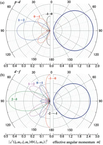
Figure1(a) and (b) show the polar angle (𝜃𝑘) dependence of𝑝to𝑑and𝑑to𝑓 tran-sition probabilities. The left panels of Figure1summarize the final state spherical harmonics for a𝑙i→ 𝑙f= 𝑙i+1channel. The transition probability from each atomic orbital by CPL excitation is indicated. The right panel shows the effective MQN. For instance, in the case of a𝑝 → 𝑑transition, the final states of𝑚f= 0,1, and2 are the majority at the emission angle of0∘,45∘, and90∘, respectively, as shown in Figure1(a). In the case of𝑑 → 𝑓transition as shown in Figure1(b), contribu-tions to𝑚∗f(90∘)for𝑚f = 0and2will be0, while that of𝑚fwith±1will be0at 𝜃out= 63.43∘. By setting appropriate incident angle, photoelectron with specific
angular momentum𝑚fcan be excluded.
The photoelectron is partially scattered by the surrounding atoms. Direct and scattered waves interfere and form photoelectron diffraction patterns, and FFPs at the directions of surrounding scattering atoms. The photoelectron wave propa-gates perpendicular to the photoelectron isophase plane,exp[𝑖(𝑘𝑟 + 𝑚∗f𝜙)]. The real part of a simulatedCu 3𝑑photoelectron wave function from aCu 9-atom cluster excited by CPL is shown in Figure2[14]. The center atom is the photoelec-tron emitter. The kinetic energy was set to914 eV. Red and blue wave fronts cor-respond to direct and scattered photoelectron waves, respectively. The effective MQN of photoelectron is non-zero in the case of CPL excitation, thus the isophase plane of photoelectron direct wave is a spiral. This causes the rotation of the FFP
Figure 1: Left panels: Polar angle𝜃𝑘dependence of the transition probabilities from each atomic orbital by circularly polarized light excitation for (a)𝑝 to 𝑑 and (b) 𝑑 to 𝑓 transitions. Right panels: same as left panels but for the effective angular momenta for photoelectrons.
Figure 2: Real part ofCu 3𝑑 photoelectron wave function from a Cu 9-atom cluster excited by circularly polarized light. Center atom is photoelectron emitter. Incident photon axis is perpendicular to the cluster plane. Kinetic energy was set at914 eV. The directions of forward focusing peaks (FFPs) shift rotationally due to angular momentum transfer from incident photon. Red and blue wave fronts correspond to the direct and scattered photoelectron waves.
direction around the incident light axis toward the same direction as the helicity of CPL. The rotation angleΔ𝜙is well described by the Daimon formula [5,15]:
Δ𝜙 = tan−1 𝑚∗f(𝜃𝑘)
𝑘𝑅 sin2𝜃 𝑘
, (7)
where𝑘is the wave number of photoelectron. The shiftΔ𝜙is inversely propor-tional to the interatomic distance𝑅between the photoelectron emitter and the scattering atoms. Thus, the local stereoscopic atomic arrangements can be imaged directly with a stereograph which consists of a pair of PIADs excited by CPL [5,15–
17].
2.2 Angular momentum of the Auger electron
After the core-hole creation, two electrons labeled1and2and occupying𝜓Aand 𝜓B, take parts in the succeeding Auger electron emission process. Here, the wave
functions for the core hole and the Auger electron are denoted as𝜓𝑙
i𝑚iand𝜓𝑙f𝑚f,
re-spectively. Consequently, the Auger electron transition probability𝜔fiis expressed as follows [18–20]. 𝜔fi = ℏ−2|𝐷 − 𝐸|2 (8) direct: 𝐷 = ⟨𝜓𝑙 f𝑚f(2)𝜓𝑙i,𝑚i(1)||𝑟1− 𝑟2| −1|𝜓 A(1)𝜓B(2)⟩ (9) exchange: 𝐸 = ⟨𝜓𝑙 f𝑚f(2)𝜓𝑙i,𝑚i(1)||𝑟1− 𝑟2| −1|𝜓 A(2)𝜓B(1)⟩ (10)
Separation of the matrix element𝐷and𝐸into radial and angular factors is ac-complished by expressing the Coulomb interaction potential in terms of products of spherical harmonics, 1 |𝑟1− 𝑟2| = ∑𝜈𝜎 4𝜋 2𝜈 + 1𝛾𝜈(𝑟1, 𝑟2)𝑌𝜈𝜎∗(𝑟1)𝑌𝜈𝜎(𝑟2), (11) where 𝛾𝜈(𝑟1, 𝑟2) = 𝑟𝜈 1/𝑟2𝜈+1, 𝑟1< 𝑟2 (12) = 𝑟2𝜈/𝑟1𝜈+1, 𝑟1> 𝑟2. (13) Refer to elsewhere for the radial factors [21–23]. The transition probability for 𝑌𝑙f𝑚f(𝜃, 𝜙)final state is the square of𝑑𝑙
f𝑚f which is the sum of Gaunt coefficient
products for each spherical harmonic operator. 𝑑𝑙f𝑚f = ∑ 𝜈𝜎 4𝜋 2𝜈 + 1⟨𝑌𝑙f𝑚f|𝑌𝜈𝜎|𝑌B⟩⟨𝑌𝑙i𝑚i|𝑌 ∗ 𝜈𝜎|𝑌A⟩ (14)
= ∑ 𝜈𝜎𝑐 𝜈(𝑙 f, 𝑚f, 𝑙B, 𝑚B)𝑐𝜈(𝑙i, 𝑚i, 𝑙A, 𝑚A) (15) 𝑒𝑙f𝑚f = ∑ 𝜈𝜎𝑐 𝜈(𝑙 f, 𝑚f, 𝑙A, 𝑚A)𝑐𝜈(𝑙i, 𝑚i, 𝑙B, 𝑚B) (16)
𝜈is a non-negative integer.𝜎is an integer between−𝜈and𝜈. In the case of direct transition,𝜈and𝜎have the following relations with quantum numbers.
𝜈 = |𝑙f− 𝑙B| = | − 𝑙i+ 𝑙A| (17)
𝜎 = 𝑚f− 𝑚B = −𝑚i+ 𝑚A (18)
Note that the angular momentum (𝜎) released by the electron filling the core hole is transferred to the emitted Auger electron. In case of𝐿2,3𝑀4,5𝑀4,5Auger electron emission, i.e., transition between3𝑑and2𝑝core levels,𝜈is equal to1. This can be understood that a virtual photon emitted by the𝜓A→ 𝑌𝑙
i𝑚itransition triggers
the𝜓B → 𝑌𝑙
f𝑚fAuger electron emission transition.
In some cases, the quantum numbers(𝑙i, 𝑚i)of the core-hole state can be specified by tuning the excitation photon energy at the resonance and selecting the destination conduction band state (CB) for the core-level electron by polarized light excitation. In the present case ofCuLMM Auger electrons, we used the reso-nant transition of2𝑝(𝑙i= 1) to4𝑠(𝑙CB= 0,𝑚CB= 0) by the CPL excitation (𝜎 = ±1) to specify the MQN of initial state as𝑚CB − 𝜎 = −𝜎. Furthermore, the different two-hole final states𝜓A𝜓B can be accessed individually by analyzing the corre-sponding Auger electron kinetic energies since the two-hole final states𝜓A𝜓Bare energetically separated.
Normally, the angular momentum of photon is transferred mostly to the pho-toelectron, however, at the absorption edge, the angular momentum is partially transferred to the resonant Auger electrons when a MQN-polarized core hole is generated [8].
3 Experimental details
The single-crystallineCu(111)and(001)surfaces were sputtered withAr+ions and annealed up to500∘Cin ultra high vacuum condition to obtain clean sur-faces. The quality of the substrate surfaces was checked by electron diffraction, Cuphotoelectron spectroscopy, and their angular distributions [24,25]. No con-tamination was identified.
The[101]FFP intensity from theCu(111)surface as a function of photoelec-tron kinetic energy and photon energy was measured using a concentric hemi-spherical energy analyzer at the soft x-ray beamline X03DA (Photoemission and
atomic resolution laboratory; PEARL) of Swiss Light Source (SLS). Linearly polar-ized light was used in the present study [26]. The emission angle relative to the incident photon axis was fixed at60∘. The sample was mounted on a6-axis ma-nipulator.
Cu 3𝑑PIAD andLMM Auger electron intensity angular distribution (AIAD) from theCu(001)surface were measured using a display-type spherical mirror analyzer (DIANA) [27,28] at the circularly-polarized soft x-ray beamline BL25SU of SPring-8, Japan [29]. Details of PIAD data processing are described elsewhere [30]. The helicity (𝜎 = ±1) of monochromatized CPL at BL25SU was reversed by switch-ing the path of the storage rswitch-ing electrons in twin helical undulators at0.1 Hz[31]. The acceptance solid angle of the analyzer was1𝜋steradian (±60∘). Electrons emitted from the sample were energy-analyzed, and their angular distributions were projected onto the fluorescent screen. The photon energy resolution was about100 meV. The electron energy resolution is determined by the analyzer en-ergy window width as indicated below for each measurement.
The photon energy of theCu 𝐿3absorption threshold measured at BL25SU [8] was larger than the measurements at X03DA and the other facilities [32,33] by about1 eV, probably due to the technical issue of the analyzer work function eval-uation for the photon energy calibration.
4 Results and discussion
4.1 Kinetic energy and photon energy mapping
We measured the nearest neighboring atom FFP intensity at the[101]direction from theCu(111)surface as a function of photon energy and photoelectron ki-netic energy at X03DA, PEARL. Figure3(a) shows a two-dimensional intensity map. Abscissa and ordinate are photon energy and photoelectron kinetic energy, respectively. Diagonal lines where the kinetic energy increases with slope1with the photon energy correspond to states with constant binding energies. In the present case, valence band photoelectrons were clearly observed. By averaging the FFP intensity for various photon energies at each kinetic energy, an x-ray excited Auger electron spectrum was obtained as shown in Figure3(b). TheCu 𝐿2𝑀4,5𝑀4,5Auger electron at a kinetic energy around934 eVappears as a hori-zontal line with a constant kinetic energy starting from photon energy of953.0 eV in Figure3(a). The horizontal lines with a constant kinetic energy starting from a photon energy of933.1 eVcorrespond to the𝐿3𝑀4,5𝑀4,5Auger electrons. The strongest intensity peak at the kinetic energy of914 eVand the second largest
Figure 3: (a) A two-dimensional intensity map of the[101] FFP. Abscissa and ordinate are photon energy and photoelectron kinetic energy, respectively. Valence band photoelectron was observed as a diagonal line. (b) An x-ray excited Auger electron spectrum obtained by averaging the FFP intensity for various photon energies at each kinetic energy. (c) An x-ray absorption spectrum obtained by averaging the FFP intensity for various kinetic energies at each photon energy. (d) The𝐿3and𝐿2absorption edge region intensity mapped in a logarithm scale.
peak at917 eVcorrespond to the two-hole final state of the1𝐺4and the3𝐹2,3,4 mul-tiplets, respectively. The1𝑆0multiplet peak was observed at910 eV. The shoulder structure at915 eVcorresponds to1𝐷2and3𝑃0,1,2multiplets [20].
On the other hand, by averaging the FFP intensity for various kinetic energies at each photon energy, an x-ray absorption spectrum was obtained. The𝐿3and𝐿2 absorption thresholds appear at the photon energies of933.1 eVand953 eV, re-spectively. Note that Auger-electron-like feature with a kinetic energy of911.8 eV appeared at a photon energy above the𝐿2 absorption threshold but not below
the threshold. Moreover,𝐿3𝑀4,5𝑀4,5Auger electron intensity is also enhanced at the𝐿2edge. These are the effects due to𝐿2𝐿3𝑀4,5Coster–Kronig transitions which has been observed [20,34] and studied experimentally [35–37] and theoreti-cally [21,22,38]. The energy difference between the911.8-eVpeak (three-hole final state) and corresponding3𝐹 𝐿2𝑀4,5𝑀4,5peak (two-hole final state) was24.7 eV which is larger than the spin-orbital splitting of19.9 eV. The difference of4.8 eV is due to the difference in the two-hole and three-hole final states [39]. Figure3(d) shows the𝐿3and𝐿2absorption edge region intensity map replotted in a logarith-mic scale. Below the absorption thresholds, photoelectron-like resonance Raman Auger scattering effects are detected [32,33]. The multiplet structure was also ob-served in the resonance Raman Auger electron spectra for the first time at the𝐿3 edge as well as the𝐿2edge. They are connected to the corresponding Auger elec-tron lines of1𝐺4,3𝐹2,3,4, and1𝑆0.
4.2 Circular dichroism in angular distributions
The prominent FFP angular circular dichroism was also observed in the valence band PIADs at the high kinetic energy of around500 eV[6]. Recently, extraor-dinary large angular momentum transfer to the resonant Auger electron where the excited core electron is trapped at conduction band was found by Morscher et al. [40] forNi 𝐿2absorption. We reported a quantitative analysis of angular-momentum-polarized𝐿3𝑀4,5𝑀4,5Auger electrons from a nonmagneticCu(001) surface at𝐿3absorption threshold. Upon detection of each angular-momentum-polarized Auger electron, the element- and MQN-specific hole in valence band is generated correspondingly.
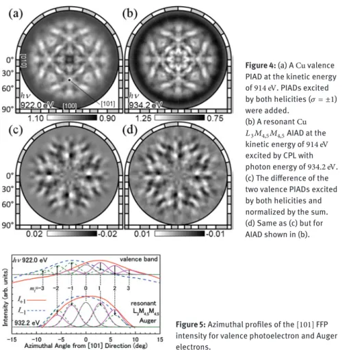
We measured full hemisphere PIAD and AIAD from theCu(001)surface at BL25SU, SPring-8 [8]. Figure4(a) shows aCuvalence PIAD at the kinetic energy of914 eV. PIADs excited by both helicities (𝜎 = ±1) were added. The incidence direction of CPL, i.e. the quantization axis, was aligned along the surface nor-mal. The energy window width of DIANA was set to5%of914 eVand the whole valence band intensity or𝐿3𝑀4,5𝑀4,5Auger electrons were integrated. The FFPs at the four⟨101⟩directions correspond to the scattering by the nearest neighbor atoms, while the center[001]direction corresponds to the second nearest neigh-bor atoms along the surface normal. Note that at this kinetic energy, FFP is also present even for a delocalized valence band due to the majority of the excitation coming from electron density existing at the vicinity of nucleus [6]. The FFP cov-ers about10∘solid angle. Figure4(b) shows a resonantCu 𝐿3𝑀4,5𝑀4,5AIAD at the kinetic energy of914 eVexcited by CPL with photon energy of934.2 eV.
Figure 4: (a) ACu valence PIAD at the kinetic energy of914 eV. PIADs excited by both helicities (𝜎 = ±1) were added. (b) A resonantCu 𝐿3𝑀4,5𝑀4,5AIAD at the kinetic energy of914 eV excited by CPL with photon energy of934.2 eV. (c) The difference of the two valence PIADs excited by both helicities and normalized by the sum. (d) Same as (c) but for AIAD shown in (b).
Figure 5: Azimuthal profiles of the[101] FFP intensity for valence photoelectron and Auger electrons.
Figure4(c) shows circular dichroism angular distibution (CDAD) of the va-lence band, i.e. the difference of the two PIADs excited by both helicities and nor-malized by the sum;(𝐼1−𝐼−1)/(𝐼1+𝐼−1). The suffix denotes the helicity. Figure4(d) shows the CDAD of the resonant AIAD. This result indicates that at𝐿3absorption threshold, where the excited core electron is trapped in conduction band, the an-gular momentum was partially transferred to the resonant𝐿3𝑀4,5𝑀4,5Auger elec-trons instead.
As shown in Figure5, the azimuthal intensity profiles of the[101]FFPs ex-cited by CPL were individually fitted by Gaussians centered at𝜙 = 2.89∘𝑚f direc-tions corresponding to the different angular momenta of emitted electrons. Note that the photoelectrons from3𝑑valence band gain angular momentum𝜎by CPL excitation (𝑚f= 3,2,∼ −1), while the angular momenta ofLMM Auger electrons
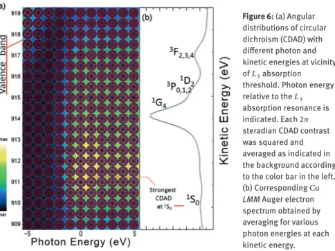
Figure 6: (a) Angular distributions of circular dichroism (CDAD) with different photon and kinetic energies at vicinity of𝐿3absorption
threshold. Photon energy relative to the𝐿3 absorption resonance is indicated. Each2𝜋 steradian CDAD contrast was squared and averaged as indicated in the background according to the color bar in the left. (b) CorrespondingCu
LMM Auger electron
spectrum obtained by averaging for various photon energies at each kinetic energy.
are the same as those of3𝑑valence electrons (𝑚i= ±2,±1,0). The components of𝑚f = ±3do not exist in the FFP of AIAD as shown in Figure5. The origin of circular dichroism in the resonant AIAD at𝐿3 absorption threshold, where the excited core electron is trapped at conduction band, is attributed to the transition difference to the final states𝑚f = ±1as well as±2.
4.3 Various two-hole final states
Details of the kinetic energy and photon energy dependence of circular dichro-ism were surveyed at the vicinity of the𝐿3absorption edge. Figure6(a) shows the CDAD contrasts measured using DIANA with the analyzer energy window width of2 eV. The kinetic energy indicated here was about1.5 eVlarger than the ac-tual value. The excitation photon energy relative to the absorption threshold is indicated. The corresponding Auger electron spectrum is shown in Figure6(b). The Auger electron intensity was largest at914 eVcorresponding to the1𝐺4 two-hole state, while the circular dichroism contrast was largest at910 eV correspond-ing to the satellite peak of1𝑆0two-hole state. At the𝐿3absorption threshold,2𝑝 core electron is excited to 4𝑠conduction band. Since the MQN of4𝑠state is 0, orbital-momentum-polarized core hole with𝑚i= ∓1is created by𝜎 = ±1
excita-tion. Several Auger decay paths with different final states exist. Final states with different energy can be selected by the energy analysis of Auger electron. The final state1𝑆0consists of two hole states having angular momentum with opposite sign (𝑚A= −𝑚B). When a valence electron with𝑚A= −1decays to fill2𝑝(𝑚i= −1) core hole, another valence counterpart with𝑚B= 1is emitted as𝐿3𝑀4,5𝑀4,5Auger electron of1𝑆0. Dipole operators𝑌10 and𝑌10∗ mediate these processes. The ex-change term (Equation11) is forbidden. When valence electrons with 𝑚A= −2 and0decay, the counterparts will be the ones with𝑚B = 2and0, respectively. Since the angular momentum is conserved throughout whole process, an Auger electron with𝑚f = 1is emitted by a𝜎 = 1excitation in the case of1𝑆0two-hole final state.
5 Conclusion
In conclusion, we have measured a full hemisphere intensity angular distribution of resonant𝐿3𝑀4,5𝑀4,5Auger electrons excited by CPL, as well as that of3𝑑 va-lence photoelectron. In the case of resonant Auger electrons where the excited core electron is trapped at the conduction band, the CDAD contrast was clearly observed. Moreover, from the kinetic energy dependence of Auger electron FFP parallax shift, we found that the angular momentum is transferred to the Auger electron most effectively in the case of the1𝑆0two-hole creation where two states involved have a same MQN but with opposite signs. This method has a great ad-vantage in doping the hole states in valence band as compared to the simple va-lence band photoexcitation, especially in the case of compound crystals and thin films owing to the element selectivity and high sensitivity of Auger electron emis-sion.
Acknowledgement: This work was performed with the approval of the Japan Syn-chrotron Radiation Research Institute (Proposals No. 2013B1307 and 2014B1454) and Paul Scherrer Institute. The authors deeply thank Mr. Rolf Wullschleger, Dr. Takayuki Muro, Dr. Tetsuya Nakamura, and Dr. Toyohiko Kinoshita for their support in the experiments. This research was supported by the Ministry of Ed-ucation, Science, Sports and Culture, Grant-in-Aid for Scientific Research (B), 25287075, 2013 and JSPS Grant-in-Aid for Scientific Research on Innovative Areas “3D Active-Site Science”: 26105007 2604. The experiment at Switzerland was sup-ported by the Foundation for Nara Institute of Science and Technology.
Appendix
Gaunt Coefficient. Gaunt coefficient is proportional to the product of three spher-ical harmonics integrated over the full solid angle. It is easily derived from Clebsch-Gordan coefficients. ⟨𝑙f𝑚f|𝜈𝜎|𝑙i𝑚i⟩ = 𝜋 ∫ 0 2𝜋 ∫ 0 sin 𝜃𝑑𝜃𝑑𝜙𝑌𝑙∗f,𝑚f𝑌𝜈𝜎𝑌𝑙i𝑚i (19) =√(2𝑙i+ 1)(2𝜈 + 1) 4𝜋(2𝑙f+ 1) 𝐶(𝑙i𝜈𝑙f; 000)𝐶(𝑙i𝜈𝑙f; 𝑚i𝜎𝑚f) (20) =√2𝜈 + 1 4𝜋 𝑐𝜈(𝑙f, 𝑚f, 𝑙i, 𝑚i) (21) s → p : 𝑙i = 0, 𝑙f= 1 p → d : 𝑙i = 1, 𝑙f= 2 𝑐1(1, ±1, 0, 0) = 1/√3 𝑐1(2, ±2, 1, ±1) = √2/5 𝑐1(1, 0, 0, 0) = 1/√3 𝑐1(2, ±1, 1, ±1) = 1/√5 p → s : 𝑙i = 1, 𝑙f= 0 𝑐1(2, 0, 1, ±1) = 1/√15 𝑐1(0, 0, 1, ±1) = −1/√3 𝑐1(2, ±1, 1, 0) = 1/√5 𝑐1(0, 0, 1, 0) = 1/√3 𝑐1(2, 0, 1, 0) = 2/√15 d → p : 𝑙i= 2, 𝑙f = 1 d → f : 𝑙i= 2, 𝑙f = 3 𝑐1(1, ±1, 2, ±2) = −√2/5 𝑐1(3, ±3, 2, ±2) = √3/7 𝑐1(1, ±1, 2, ±1) = 1/√5 𝑐1(3, ±2, 2, ±2) = 1/√7 𝑐1(1, ±1, 2, 0) = −1/√15 𝑐1(3, ±1, 2, ±2) = 1/√35 𝑐1(1, 0, 2, ±1) = −1/√5 𝑐1(3, ±2, 2, ±1) = √2/7 𝑐1(1, 0, 2, 0) = 2/√15 𝑐1(3, ±1, 2, ±1) = 2√2/35 𝑐1(3, 0, 2, ±1) = √3/35 𝑐1(3, ±1, 2, 0) = √6/35 𝑐1(3, 0, 2, 0) = 3/√35
Transition probability. Transition probability from the initial state (𝑙i,𝑚i) to the
final state (𝑙f,𝑚f) is the square of𝐶1(𝑙f, 𝑚f, 𝑙i, 𝑚i)𝛩𝑙
f𝑚f. s → p : p → s : 𝑐1(1, ±1, 0, 0)𝛩1±1= sin 𝜃2 𝑐1(0, 0, 1, ±1)𝛩00 = −√61 𝑐1(1, 0, 0, 0)𝛩 10 = cos 𝜃√2 𝑐1(0, 0, 1, 0)𝛩00= √61 p → d : d → p : 𝑐1(2, ±2, 1, ±1)𝛩 2±2= √3 sin 2𝜃 2√2 𝑐 1(1, ±1, 2, ±2)𝛩 1±1 = −√3 sin 𝜃√10 𝑐1(2, ±1, 1, 0)𝛩2±1 = √3 sin 𝜃 cos 𝜃 2 𝑐1(1, 0, 2, ±1)𝛩10 = −√3 cos 𝜃√10 𝑐1(2, 0, 1, ∓1)𝛩20= 3 cos2𝜃 − 1 2√6 𝑐 1(1, ∓1, 2, 0)𝛩 1∓1= −sin 𝜃2√5
𝑐1(2, ±1, 1, ±1)𝛩2±1= √3 sin 𝜃 cos 𝜃2 𝑐1(1, ±1, 2, ±1)𝛩1±1 = √3 sin 𝜃
2√5 𝑐1(2, 0, 1, 0)𝛩 20 = 3 cos 2𝜃 − 1 √6 𝑐1(1, 0, 2, 0)𝛩10= √2 cos 𝜃√5 d → f : 𝑐1(3, ±3, 2, ±2)𝛩3±3= √308 sin3𝜃 𝑐1(3, ±2, 2, ±1)𝛩3±2= √30 4 sin2𝜃 cos 𝜃 𝑐1(3, ±1, 2, 0)𝛩3±1= 3 4√5sin 𝜃 (5 cos 2𝜃 − 1) 𝑐1(3, 0, 2, ∓1)𝛩3,0= 12√ 310(5 cos3𝜃 − 3 cos 𝜃) 𝑐1(3, ∓1, 2, ∓2)𝛩 3,∓1 = 14√ 310sin 𝜃 (5 cos2𝜃 − 1) 𝑐1(3, ±2, 2, ±2)𝛩 3±2= √154 sin2𝜃 cos 𝜃 𝑐1(3, ±1, 2, ±1)𝛩 3±1= 12√35sin 𝜃 (5 cos2𝜃 − 1) 𝑐1(3, 0, 2, 0)𝛩30 = 3 2√10(5 cos 3𝜃 − 3 cos 𝜃)
References
1. C. S. Fadley, J. Electron Spectrosc.178–179 (2010) 2.
2. S. Kono, S. M. Goldberg, N. F. T. Hall, C. S. Fadley, Phys. Rev. B22 (1980) 6085. 3. W. F. Egelhoff Jr., Phys. Rev. B30 (1984) 1052.
4. H. C. Poon and S. Y. Tong, Phys. Rev. B30 (1984) 6211. 5. H. Daimon, Phys. Rev. Lett.86 (2001) 2034.
6. F. Matsui, T. Matsushita, Y. Kato, F. Z. Guo, and H. Daimon, J. Phys. Soc. Jpn.76 (2007) 013705.
7. K. Goto, F. Matsui, T. Matsushita, Y. Kato, and H. Daimon, J. Phys. Soc. Jpn.77 (2008) 103301.
8. F. Matsui, M. Fujita, T. Ohta, N. Maejima, H. Matsui, H. Nishikawa, T. Matsushita, and H. Daimon, Phys. Rev. Lett.114 (2015) 015501.
9. S. M. Goldberg, C. S. Fadley, and S. Kono, J. Electron Spectrosc.21 (1981) 285. 10. J. A. Gaunt, Trans. Roy. Soc. LondonA228 (1928) 195.
11. T. Greber, J. Phys.-Condens. Mat.13 (2001) 10561.
12. F. Matsui, H. Miyata, O. Rader, Y. Hamada, Y. Nakamura, K. Nakanishi, K. Ogawa, H. Namba, and H. Daimon, Phys. Rev. B72 (2005) 195417.
13. H. Daimon, S. Imada, and S. Suga, Surf. Sci.471 (2001) 143. 14. http://sourceforge.jp/projects/tmcoca/.
15. H. Daimon, T. Nakatani, S. Imada, S. Suga, Y. Kagoshima, and T. Miyahara, Jpn. J. Appl. Phys.32 (1993) L1480.
16. F. Matsui, T. Matsushita, and H. Daimon, J. Electron Spectrosc.178–179 (2010) 221. 17. F. Matsui, N. Nishikayama, N. Maejima, H. Matsui, K. Goto, M. Hashimoto, T. Hatayama,
T. Matsushita, Y. Kato, and H. Daimon, J. Phys. Soc. Jpn.80 (2011) 013601. 18. V. O. Kostroum, M. H. Chen, and B. Crasemann, Phys. Rev. A3 (1971) 533.
19. W. Bambynek, B. Crasemann, R. W. Fink, H.-U. Freund, H. Mark, C. D. Swift, R. E. Price, and P. Venugopara Rao, Rev. Mod. Phys.44 (1972) 716.
20. E. Antonides, E. C. Janse, and G. A. Sawatzky, Phys. Rev. B15 (1977) 1669. 21. P. J. Feibelman, and E. J. McGuire, Phys. Rev. B15 (1977) 3575.
22. E. J. McGuire, Phys. Rev. A17 (1978) 182.
23. S. Aksela and J. Sivonen, Phys. Rev. A25 (1982) 1243.
24. T. Matsushita, F. Z. Guo, F. Matsui, Y. Kato, and H. Daimon, Phys. Rev. B75 (2007) 085419. 25. F. Matsui, T. Matsushita, Y. Kato, M. Hashimoto, K. Inaji, F. Z. Guo, and H. Daimon, Phys.
Rev. Lett.100 (2008) 207201.
26. P. Oberta, U. Flechsig, M. Muntwiler, and C. Quitmann, Nucl. Instrum. MethodsA635 (2011) 116.
27. H. Daimon, Rev. Sci. Instrum.59 (1988) 545.
28. M. Kotsugi, Y. Miyatake, K. Enomoto, K. Fukumoto, A. Kobayashi, T. Nakatani, Y. Saitoh, T. Matsushita, S. Imada, T. Furuhata, S. Suga, K. Soda, M. Jinno, T. Hirano, K. Hattori, and H. Daimon, Nucl. Instrum. MethodsA467–A468 (2001) 1493.
29. Y. Saitoh, H. Kimura, Y. Suzuki, T. Nakatani, T. Matsushita, T. Muro, T. Miyahara, M. Fuji-sawa, K. Soda, S. Ueda, H. Harada, M. Kotsugi, A. Sekiyama, and S. Suga, Rev. Sci. In-strum.71 (2000) 3254.
31. T. Muro, T. Nakamura, T. Matsushita, H. Kimura, T. Nakatani, T. Hirono, T. Kudo, K. Kobayashi, Y. Saitoh, M. Takeuchi, T. Hara, K. Shirasawa, and H. Kitamura, J. Electron Spectrosc.144–147 (2005) 1101.
32. I. Coulthard, T. K. Sham, Y.-F. Hu, S. J. Naftel, P.-S. Kim, and J. W. Freeland, Phys. Rev. B64 (2001) 115101.
33. A. Föhlisch, O. Karis, M. Weinelt, J. Hasselström, A. Nilsson, and N. Mårtensson, Phys. Rev. Lett.88 (2001) 027601.
34. H. H. Madden, D. M. Zehner, and J. R. Noonan, Phys. Rev. B17 (1978) 3074. 35. H. W. Haak, G. A. Sawatzky, and T. D. Thomas, Phys. Rev. Lett.41 (1978) 1825. 36. C. P. Lund, S. M. Thurgate, and A. B. Wedding, Phys. Rev. B55 (1997) 5455. 37. M. Magnuson, N. Wassdahl, and J. Nordgren, Phys. Rev. B56 (1997) 12238. 38. L. C. Davis and L. A. Feldkamp, Phys. Rev. B23 (1981) 6239.
39. N. Mårtemsson and B. Johansson, Phys. Rev. B28 (1983) 3733.
![Figure 3: (a) A two-dimensional intensity map of the [101] FFP. Abscissa and ordinate are photon energy and photoelectron kinetic energy, respectively](https://thumb-eu.123doks.com/thumbv2/123doknet/14812660.611996/9.659.75.570.92.575/figure-dimensional-intensity-abscissa-ordinate-photoelectron-kinetic-respectively.webp)