Design and Development of Advanced Load Sensors
for the International Space Station
by
Amir R. Amir
B.S., Aeronautics and Astronautics
Massachusetts Institute of Technology, 1993
S.M., Aeronautics and Astronautics
Massachusetts Institute of Technology, 1995
Submitted to the Department of Aeronautics and Astronautics
in Partial Fulfillment of the Requirements for the Degree of
Engineer in Aeronautics and Astronautics
at the
Massachusetts
Institute of Technology
September 1998
© 1998 Massachusetts Institute of Technology. All rights reserved.
Signature of A uthor
...
Department of Aeronautics and Astronautics
September 1, 1998
C
ertified b
y ...
Dava J. Newman, Agsociate Professor of Aeronautics and Astronautics
Thesis Supervisor
A ccepted by
...
...
Jaime Peraire
Chairman, DepartmentjGraduate Committee
€ '•.' irCH-ETT INST1'M"F TEC'-'(OGY
SEP
•22
"
•e
S\ero
Design and Development of Advanced Load Sensors
for the International Space Station
by
Amir R. Amir
Submitted to the Department of Aeronautics and Astronautics on September 1, 1998 in partial fulfillment of the requirements for the
Degree of Engineer in Aeronautics and Astronautics
ABSTRACT
In preparation for the construction of the International Space Station (ISS) a risk mitigation exper-iment was conducted to quantify the crew-induced disturbances to the microgravity environment on board a spacecraft during a long duration space flight. Achieving a microgravity environment for scientific experiments is one of the primary objectives of the ISS. While numerous measure-ments have been made to characterize the overall acceleratory environment on the Space Shuttle and on Mir, the contribution of astronaut motion to the disturbances was little understood.
During the first phase of the ISS Program, the stay of U.S. astronauts on the Russian Orbital Com-plex Mir, the Enhanced Dynamic Load Sensors (EDLS) Spaceflight Experiment measured from May 1996 to May 1997 the forces and moments that astronaut exerted on the space station. Using four instrumented crew restraining and mobility devices, a handhold, two foot loops, and a touch-pad, 133 hours of data was recorded during nominal crew activities and scientific experiments.
The thesis gives a historical overview of the research that has been conducted to quantify the crew-spacecraft interaction. A description of the EDLS experiment set-up and timeline as well as the custom-designed experiment hardware and software is provided. Due to an on-orbit failure of the original data acquisition system, a replacement computer was used to continue the experiment. The post-flight efforts to calibrate the replacement hardware, catalog the data files, and the tests to determine the condition of the sensors are presented. A cross-platform EDLS-specific software package was developed to aid in the analysis of the spaceflight data. The requirements, underlying signal processing equations, and the implementation in MATLAB are discussed. A preliminary design of advanced sensors for the ISS is developed in the thesis. While, retaining the proven strain-gage based method of sensing forces and moments, the restraining portion of the sensors was redesigned to aid astronauts better and can be easily exchanged for a different functionality. While having a volume of only 5800 cubic centimeters, the sensor electronics unit (SEU) incorpo-rates most of the features of the original computer eight times its size. The SEU features an advanced embedded computer system and a Java-based operating system. Feedback on the loads applied can be provided in near real-time to the crew to aid the astronauts in maintaining a quies-cent environment on the station during critical microgravity experiments.
Thesis Supervisor: Dava J. Newman, Ph.D.
ACKNOWLEDGMENTS
My foremost thanks belong to my advisor Professor Dava Newman. I am deeply grateful for all your support, encouragement, enthusiasm, and trust. Thank you for allowing me to work on an exciting spaceflight experiment. I am greatly appreciative of the guidance provided by my committee members Professors Jack L. Kerrebrock, Manuel Martinez-Sanchez, and Stanley I. Weiss. Your support has been a great honor for me.
Thanks is owed to NASA's Office of Life Sciences Research which funded the EDLS risk mitigation experiment for the International Space Station under contract NAS 1-18690. Sherwin Beck has been the co-investigator on EDLS from NASA the general liaison to the agency. Thank you so much for all your help during the First Phase I Research Symposium in Houston. It was a real pleasure to attend the symposium with you and I hope to see you again soon.
The people of Payload Systems, Inc. and Mid6 Inc. in Cambridge built the EDLS spaceflight hardware and much the success of the experiment is due to their knowledge and ingenuity. To Tienie: I am very grateful to you for explaining the sensor technology and so much else. The more I know you, the more I am amazed about your knowledge-you have been practically a co-advisor to me and I thank you for that. To Kim: Thank you so much for answering my questions about EDLS in general, finding all the bits of information I asked for, and being a great liaison on this project. To Joe. I do not know how many times I called you or visited you to ask you a question but I know that you always had time for me and answered my questions patiently. Thanks! It was a great pleasure working with you. To Ed. While Joe is the software wizard, Ed and Stephan are the hardware wizard. Thanks so much for all the information you provided and building the ground sensors. I won't forget your help! Last not least, thanks to you Javier for keeping everything organized and for allowing me to roam around your facili-ties and take time from your employees. I am also indebted to Paul Bauer for his work on the strain gages and for being the source of great ideas.
Several students worked with me on EDLS: fellow graduate student and office mate Natasha Neogi, UROPers Jennifer Bonnell, Larry Pilkington, and Shane Suehisa. You did a terrific job and I could not have done it if was not for your enormous help. Your enthusiasm for the project, your eagerness to learn, and the willingness to do boring but necessary work made it so nice to work with you.
Simone, you have my deep gratitude not only for your valuable technical advice but also for becoming such a good friend over the course of the last year. Thanks also belong to another Italian, Guido Bar-oni. It was fun to have you here at MIT this past summer. I am looking forward seeing the advanced EDLS sensors work with your ELITE system on the International Space Station a few years from now. Many other people have helped me throughout this project and I would like to express my sincere appreciation to them. They are MIT Aero/Astro Librarian Eileen Dorschner, Kim Kilman from the ISS Program Library, Peter Bruckner and Joel Gwynn of Designer's CADD, Inc., Craig A. Haller of Mac-raigor Systems Inc., and Chris Lines from the Motorola Semiconductor Group who generously pro-vided me with a Motorola PowerPAQ. To Liz Zotos. Thanks for your patience.
Thanks are also due to Dr. Charles Oman, director of the MVL, and the other students in the lab, spe-cifically Rex, Luca, Susan, Joe, and Jen, for creating such a pleasant environment to work. My family
Acknowledgments
has always been an important part of my life and what I am I owe to them. I would like to thank or all their sacrifices, support, encouragement, help, and love.
ACRONYMS
A/D Analog-to-Digital
AFR Anchor Foot Restraint ARIS Active Rack Isolation System
ASIC Application Specific Integrated Circuit
CDR Commander
COTS Commercial Off-the-Shelf CSA Canadian Space Agency d.o.f. degree(s) of freedom
D/A Digital-to-Analog
DLS Dynamic Load Sensors
EDLS Enhanced Dynamic Load Sensors EMI Electromagnetic Interference
ESA European Space Agency
ESM Experiment Support Module
ESRD Experiment Support Requirements Document EVA Extra-vehicular Activity
FCS Flight Crew Systems
FD Flight Day
FE Flight Engineer
FEM Finite Element Model
FFT Foot restraint 1, Foot restraint 2, Touchpad FHT Foot restraint 1, Handhold, Touchpad FR Foot restraint or Functional Requirement
HH Handhold
ISS International Space Station
ISSCB International Space Station Control Board IVA Intra-Vehicular Activity
JSC NASA Johnson Space Center LaRC NASA Langley Research Center
LDCR Long Duration Crew Restraint LDFR Long-Duration Foot Restraint
LEO Low Earth Orbit
Acronyms
MASU Mir Auxiliary Sensor Unit
MGMAIT Microgravity Multidisciplinary Analysis Integration Team MiSDE Mir Structural Dynamics Experiment
MIT Massachusetts Institute of Technology MODE Middeck 0-Gravity Dynamics Experiment
MODE-R Middeck 0-Gravity Dynamics Experiment Reflight MSIS Man-Systems Integration Standards
MVL Man-Vehicle Laboratory
NASA National Aeronautics and Space Administration NASA National Aeronautics and Space Administration NASDA National Space Development Agency of Japan NRC National Research Council
OARE Orbital Aerodynamic Research Experiment PCB Printed Circuit Board
PCMCIA Personal Computer Memory Card International Association PCMCIA Personal Computer Memory Card International Association
POCC Payload Operations Control Center POSA Payload Operations Support Area PSI Payload Systems Inc.
R&MA Restraint and Mobility Aid
RAM Random Access Memory
RCS Reaction Control System RHA Rack Handle Assembly
RMS Root Mean Square
ROM Read-Only Memory
RSA Russian Space Agency
SAMS Space Acceleration Measurement System SCSI Small Computer Serial Interface
SDFR Short-Duration Foot Restraint SEU Sensor Electronics Unit SRU Sensor Restraint Unit SSF Space Station Freedom STS Space Transportation System
TP Touchpad
TSH Triaxial Sensor Head URL Uniform Resource Locator USB Universal Serial Bus
Acronyms
VAIT Vehicle Analysis and Integration Team VAT Vehicle Analysis Team
TABLE OF CONTENTS
Acknowledgments...
Acronym s...
Table of Contents...
List of Tables ...
List of Figures...
. . . .5 ... 7 .... ... ...1 1 ... ...15 ... ... .... .. .... .... 17Introduction
...
Scope of the Thesis... The DLS and EDLS Experiments ...
Sensors for the International Space Station Thesis Outline...
2
Space Stations and Microgravity
2.1 Mir Orbital Complex... The International Space Station ... Historical Perspective... Purpose, Objectives, and Organization of ISS ....
Phase I: The Shuttle-Mir Program ... ISS Phases II and III...
The Microgravity Environment... Classification of On-Orbit Disturbances... Quasi-steady Accelerations... Non-Steady Accelerations... Measurements of the Microgravity Environment. . ISS Microgravity Requirements ...
19
.19 . 20 .21 . 2325
.25 . 28 .28 . 30 .31 .33 . 36 . 38 . 38 . 40 .41 . 45Previous Research on Astronaut-Spacecraft Interaction ...
Early M odeling Efforts... ... Stochastic M odels... ...
Skylab Crew/Vehicle Disturbance Experiment ...
....
51
... 5
1
... 54 ... 55 2.2 2.2.1 2.2.2 2.2.3 2.2.4 2.3 2.3.1 2.3.2 2.3.3 2.3.4 2.43
3.1 3.2 3.3 . . . . .Table of Contents
4
The DLS/EDLS Spaceflight Experiments and their Technology
Dynamic Load Sensors Experiment on STS-62 . . . .
The Enhanced D namic Load Sensors over-iment on Mir
4.2.1 Motivation
Objectives ...
Experiment Chronology... DLS/EDLS Experimental Hardware and Software Load Sensors...
Experiment Support Module ...
Umbilical Cable / Adapter... 4.2.2 4.2.3 4.3 4.3.1 4.3.2 4.3.3
5
5.1 5.2 5.2.1 5.2.2 5.3 5.3.1 5.3.2 5.3.3 5.4Experimental IC
.. . .. . . .. . . .. . .. . . . . ... . . . .. . . .. . . . . .. . . .. . . .. . . .. . . .. .. . . . . . .. .. . . • . .. . . .. .. . .. . . .. .. . .. . . .. . .....
...
...
.• • ... •. ... .. .. .°. ...
63
... 63 ... 67 ... 67 ... 69 ... 70 ... 73 ... 74 ... 79 ... 84ata ...
87
...
87
... 88 ... 88 ... ... 9 1 ... 95 ... 95 ... 97 ... 100 ... 103Design and Development of Advanced
ISS Restraints and Mobility Aids ... 6.2 Lessons Learned from EDLS. 6.3 6.47
7.1 7.2Load Sensors...
...23
124 ... ... ... .. ... ... .. .. .... .... .. .. ... ...127Objectives, Requirements, and Constraints for Advanced Sensors Design of Advanced Load Sensors ...
Future Development ...
Data Analysis... Further Development of the Advanced Sensors ....R eferences.. ...
... 129 ... 130...
133
..
... 133
... 134 ... 137APPENDIXES
A
A.1 A.2 A.3Reference Tables ...
145
Damaged Sectors in WORM Disks...145
EDLSAP Batch File Format ... 145
Ground Sensors to IOtech Signal Conditioning Interface ... 146 4.1
4.2
Processing and Analysis of EDLS
Terminology and Notation ...
EDLS Spaceflight Experiment Data ... Data from NASA 2 Mission ... Data from NASA 4 Mission ... EDLSAP Software... EDLSAP Requirements and Features... Processing of Raw EDLS Data ... Analysis of EDLS Data... Postflight Calibration of EDLS Hardware...
J .. . .. . . .. . . . .. . .. .• . . .. . . ... . .. . . . .. .. . . . . .. .. . . .. . . S. .. . . .. .... ....°. . . . . . . . . . . .
Table of Contents
B
EDLS Sensor Machine Shop Drawings
...
149
C
MATLAB Code
...
155
C.1 EDLSAP Scripts... 155
LIST OF TABLES
The M ir M odules [40], [47], [48]...
U.S. Astronauts on the Russian Space Station Mir [40], [47]... Typical Maximum Acceleration Levels on Salyut-7 Space Station [12] Summary of SAMS-II Experiment Support Requirements [44]... Specifications of SAMS-II Units [44]...
Crew Induced Forces in a KC-135 Zero-g Aircraft Pilot Study [24] ...
.26 . 32
Chapter 1
Chapter 2
Table 2.1: Table 2.2: Table 2.3: Table 2.4: Table 2.5:Chapter 3
Table 3.1:Chapter 4
Table 4.1: Table 4.2: Table 4.3: Table 4.4: Table 4.5: Table 4.6:Chapter 5
Table 5.1: Table 5.2: Table 5.3: Table 5.4: Table 5.5: Table 5.6: Table 5.7: Table 5.8:Characteristic Astronaut Motion Identified in DLS Experiment ... 66
Timeline of the EDLS Spaceflight Experiment ... 74
Requirements for DLS/EDLS Sensors [65]...76
Structural Design Specifications for EDLS Sensors... 77
Specification of the MODE / EDLS ESM [70], [71] ... 82
EDLS Sensor and Their Channel Arrangement ... 86
EDLS Data Returned from NASA 2 Mission ... 89
Data File Format of the NASA 2 Header File ... 90
EDLS Data Returned from NASA 4 Mission...91
Channel Assignment of MASU ESM Used During NASA 4 Mission... 93
Variables Contained in EDLS Data Files ... 99
Sample Calibration Data for the Foot restraint 2 Sensor... 109
Accuracy of Post-flight Sensor Calibration ... 113
System Gains of the MASU ESM ... 115
... 4 1 ... 44
.°.°°.°°.°..°..°.44
... 45
List of Tables
Chapter 6
Chapter 7
Appendix A
Table A. 1: Damaged Data Files from NASA 2 Mission...145 Table A.2: Format of an EDLSAP Batch File for Processing Raw Data ... 146 Table A.3: Cable Connecting EDLS Ground Sensors to IOtech A/D Hardware ... 147
Appendix
B
Appendix C
Table C. 1: EDLSAP Script Files and Function Syntax ... 155
LIST OF FIGURES
Chapter 1
Figure 1.1: ... ... 21Chapter
2
Figure 2.1: .... ... 27 Figure 2.2: ... ... 28 Figure 2.3: ... ... 35 Figure 2.4: ... ... 37 Figure 2.5: ... ... 37 Figure 2.6: ... ... 47 Figure 2.7: ... ... 48Chapter
3
Figure 3.1: ... ... 56 Figure 3.2: ... 58 Figure 3.3: ... ... 60 Figure 3.4: ... 61Chapter
4
Figure 4.1: ... ... 64 Figure 4.2: ... ... 65 Figure 4.3: ... ... 67 Figure 4.4: ... ... 68 Figure 4.5: ... 72 Figure 4.6: ... ... 72 Figure 4.7: ... ... 73 Figure 4.8: ... ... 75 Figure 4.9: ... 78 Figure 4.10: ... ... 79 Figure 4.11: ... ... 80... ... . . . . .. . ... ... 8 1 ... .. ... . .... ... . ... ... . 83 ... ... ... ... 85 Figure 4.12: Figure 4.13: Figure 4.14:
Chapter 5
Figure 5.1: Figure 5.2: Figure 5.3: Figure 5.4: Figure 5.5: Figure 5.6: Figure 5.7: Figure 5.8: Figure 5.9: Figure 5.10: Figure 5.11: Figure 5.12: Figure 5.13:Chapter 6
Figure 6.1: Figure 6.2: Figure 6.3: Figure 6.4:Chapter 7
List of Figures .94 ..96 ..98..
99
.104 .105 .106 .107 .108.111
.112
.119 .120 .124 .125 .126 .127CHAPTER
1
INTRODUCTION
The engineering work described in this thesis has been carried out within the framework of the Enhanced Dynamic Load Sensors (EDLS) spaceflight experiment conducted on the Russian Space Station Mir from May 1996 to May 1997. EDLS was a follow-on experiment to the Dynamic Load Sensors (DLS) Space Shuttle middeck experiment flown on mission STS-62 in March of 1994. NASA provided funding for EDLS as a risk mitigation experiment for the International Space Station (ISS). The primary objective of both DLS and EDLS was to measure the forces and moments resulting from regular astronaut activities. One key motivation for spaceflight is to achieve a "zero-g" or, more precisely, microgravity environment for research. As a result, disturbances to this environment such as vibrations and accelerations from equipment and the astronauts should be minimized to assure that material science, life science, and physics experiments as well as astronomical observations have the best possible conditions in orbit.
1.1 Scope of the Thesis
This thesis encompasses two components. While they are distinct, one leads logically to the next. The first component is the process of converting the raw EDLS flight data into a form usable for further analysis. This work required a detailed understanding of the experimental hardware and software of which some was developed more than ten years ago. In addition, mistakes as well as areas for improvement in the design were identified. The second thesis component is the preliminary design of a new set of sensors that benefit from the experiences made on the Shuttle and on Mir. This work is well beyond what is required in the contract for EDLS. It represents the first step in the development of advanced sensors to measure astronaut-induced loads that could be built into some ISS modules per-manently to aid in the operation of the station. From a less ambitious perspective, it is the first step in the development of an EDLS follow-up experiment on ISS sometime in the first or second decade of
Chapter 1: Introduction
1.2 The DLS and EDLS Experiments
While numerous measurements of disturbances caused by mechanical systems as well as the space environment in low earth orbit (LEO) had been made, little was known about astronaut-induced distur-bances. The first experimental data came from an experiment on Skylab in 1973 in which the astro-nauts executed a set of prescribed activities and the resulting forces were measured. These activities included "vigorous soaring" as a worst-case scenario, resulting in loads close to 500 Newtons. The
peak values from the experiment were used as the characteristic force-level to be expected from crew
motion. As a result, ISS requirements expected such a load from the astronauts.
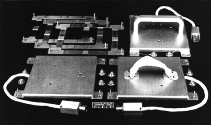
While DLS was restricted to a few days in orbit, EDLS could record data over several months. The longer timeframe yielded a larger database and the ability to quantify the change in crew motion dur-ing adaptation to the microgravity environment. Durdur-ing the three-day DLS experiment data on some 600 astronaut events where recorded. An event is a specific crew motion lasting a few seconds, such as a landing or a push-off. The experimental hardware consisted of three sensors, a hand-hold, a foot restraint, and a touchpad, similar in appearance to the devices found in the Space Shuttle orbiter to assist the crew in moving about the spacecraft. A photograph of the DLS sensors taken prior to the Shuttle flight is shown in Figure 1.1. Data recording and storage was performed by an external unit the size of a Space Shuttle middeck locker (approximately 0.046 m3 or 46 liters in volume) and weighing close to 27 kilograms.
The EDLS experiment was conducted on the space station Mir through the U.S.-Russian cooperation known as Shuttle-Mir Program, or officially, as Phase 1 of the International Space Station Project. The EDLS hardware consisted of the same devices used on DLS as well as one additional foot restraint identical to the original one (in the lower right corner of Figure 1.1) to bring the total number of sen-sors from three to four. The software for the Mir data recording computer was changed to include "event detection," to avoid a waste of storage capacity by recording continuously on the long-duration space missions.
During the Mir stay of U.S. astronaut Shannon Lucid (Mission NASA 2 to Mir) in 1996, some 2.5 GBytes of EDLS data were recorded. Due to a failure of the EDLS computer system, no data were recorded during NASA 3. In order to continue the experiment a similar computer system, made by the same manufacturer for another experiment, was utilized on the NASA 4 Mir mission. An adapter and new software were sufficient to continue the EDLS experiment with the new computer. Approximately
Section 1.3: Sensors for the International Space Station
Figure 1.1: The photographs shows the DLS sensors: a touchpad, a foot restraint, and a handhold as well
frames to anchor the sensors to the floor or walls of the orbiter. Each sensor measures about 24 by 24 cen-timeters (NASA Image 94-05316).
2.2 GBytes of data were recorded during Jerry Linenger's (Mission NASA 4) visit to Mir in 1997. While the items needed to rescue the EDLS experiment were not difficult to build, the on-orbit switch of computers resulted in a much more difficult and time-consuming post-flight data processing effort as is described in this thesis.
Following the collision of a Progress resupply vehicle with the Spektr module of Mir in June 1997 and the resulting difficulties on the orbital complex, further crew time was not available to record addi-tional EDLS data. The experimental hardware was returned to Earth on Shuttle flight STS-89 in Janu-ary 1998.
1.3 Sensors for the International Space Station
The main objective for the International Space Station is to be a "world-class laboratory" by providing scientists, engineers, and entrepreneurs (1) a research platform with a prolonged exposure to micro-gravity and (2) the presence of human inhabitants to execute and supervise experiments. Various research activities require an absolutely quiescent environment of 10-6 g or less. To provide such a
Chapter 1: Introduction
condition, Boeing offers the microgravity Active Rack Isolation System (ARIS), which is stated to attenuate structural dynamic vibrations [42]. At a cost of about $20 million and large mass and power requirements, such a system is expensive, not only in monetary terms. If the effects from crew motion are better quantified, then less-sensitive experiments can be conducted without employing isolation systems at a substantially lower cost and complexity. ISS operation will include a so-called "micro-gravity model" in which machinery on board ISS will operate to minimize vibrations and accelera-tions. During this time, the human crew must also adjust their motions accordingly to minimize forces exerted on the craft.
Official ISS documents clearly recognize the importance of investigating disturbances due to crew motion and mitigating the effects but as of mid-1998 have no plans for dealing with the issues. An advanced version of the EDLS sensors could not only store data but also provide immediate feedback to the astronauts on the magnitude of the reaction forces they cause and thus would be a valuable tool for the crew in determining whether they need to adjust their motion or not. The stored data would be examined in detail later by researchers to ensure that their experiment was not subjected to excessive loads. In conjunction with a system that has accelerometers mounted at various locations on the station to monitor the microgravity environment, a good picture of the vibrational environment and the sources for the accelerations would be obtained.
The computer system originally used with the DLS/EDLS sensors was designed in the late 1980s as a generic data acquisition and storage system to support space shuttle middeck experiments. The replacement computer used represented a somewhat more advanced version of the original system. It maintained the same size as the predecessor model but incorporated early 1990s technology to boast more features. Due to the fast pace in the electronics field, the latest commercial off-the-shelve hard-ware outperforms earlier custom-made systems by a large margin for a fraction of the mass, volume, and power. By making use of the latest advancements in electronics and by including only components of relevance to the load sensors, a next generation of sensors would permit a miniaturization so that the entire data acquisition and storage system could be incorporated into the sensors themselves. The lack of umbilical cables from the sensor to an external computers system, would result in a simpler, safer, and mobile system.
Many lessons were learned from observing the astronauts using the EDLS sensors on videotape and direct feedback from the crew. This information helped improve the mechanical portion of the sensors;
Section 1.4: Thesis Outline
that is, the top restraint portion of the sensors (i.e., the metal rail on the handhold and the canvas loops on the foot restraints).
1.4 Thesis Outline
Chapter 2 "Space Stations and Microgravity" provides background information on the Mir Orbital Complex where the EDLS data was gathered and the Shuttle-Mir Program through which the EDLS experiment was conducted. The chapter also includes a fairly detailed description of International Space Station for which the advanced sensors were designed and a general classification of the micro-gravity environment. As the name implies, Chapter 3 "Previous Research on Astronaut-Spacecraft Interaction" discusses the prior research efforts on microgravity disturbances due to crew motion and the key results obtained.
The motivation, objectives, history as well as technology of the DLS/EDLS spaceflight experiments are the subjects of Chapter 4. Chapter 5 "Processing and Analysis of EDLS Experimental Data" explains the postflight calibration process of the sensors, the processing of EDLS data and the valida-tion of the data through ground tests. Chapter 6 "Design and Development of Advanced Load Sensors" discusses the requirements for measuring crew-disturbances on ISS, the mistakes that were made in the development of the original equipment, and ends with the presentation of the preliminary design of the advanced sensors. The seventh and final thesis chapter describes the next steps in the analysis of the EDLS data, and outlines the path to complete the development of the advanced sensors.
CHAPTER
2
SPACE STATIONS AND
MICROGRAVITY
This chapter begins with a description of the Russian Mir Orbital Complex followed by background information on the International Space Station which includes the Shuttle-Mir Program, as part of which the EDLS experiment was conducted. The information provided herein is more extensive than is necessary for later chapters from a purely technical perspective, but is useful to gain an understanding for the overall environment in which the EDLS experiment was carried out and in which the advanced sensors would be used in.
Section 2.3 explains the microgravity environment and the disturbances acting on it aboard spacecraft in LEO. The section is concluded with a brief discussion of the measurements that have been taken over the last decades to characterize the microgravity environment on the Space Shuttle and Soviet space stations. The last part of this chapter examines the microgravity requirements for the Interna-tional Space Station.
2.1
Mir
Orbital
Complex
While the United States placed its emphasis on low-cost access to space through the development of the Space Shuttle, the Soviet Union favored long-duration space flight through the construction of space stations. The Russian Mir Orbital Complex is the last in a long line of Soviet/Russian space sta-tions. The history of Soviet stations can be described as one of gradual improvement, continuous upgrade of equipment, and quick recovery from failures. The first generation of Soviet space stations allowed only a temporary presence in space since they could not be resupplied or refueled. They were launched unmanned and later occupied by crews. Although there were two types, Almaz ("Diamond") military stations and Salyut civilian stations, both were called Salyut ("Salute") to confuse the West. The world's first space station, Salyut 1, was launched into orbit unmanned on April 19, 1971. The crew of Soyuz 11 lived aboard the station for three weeks but died upon return to Earth as air leaked from their cabin. The three following first-generation stations did not reach orbit or broke up before
Chapter 2: Space Stations and Microgravity
they were manned. The Soviet program recovered from this string of failures and from 1974-77 had three successful stations in orbit [48], [23], [36].
Salyut 6 and 7 were the second-generation of Soviet space stations. The former was operated from
1977 to 1982 and the latter from 1982 until 1986. They allowed a long-duration stay through the exist-ence of two docking ports of which one was used by the automated resupply vehicle Progress. A total of 26 crews visited the two stations where the longest stay was 237 days [23].
On February 19, 1986, the Soviet Union launched the Mir (meaning "Peace" and "World" in Russian) space station. Development of this third-generation station had begun in 1976 involving 200 scientific, project and construction organizations of 20 ministries and departments [45]. Mir became the world's first permanent space habitat and the first station designed to be expanded over time. At the time of launch the station weighed 20,400 kg and consisted of only one module with a total pressurized vol-ume of 90 cubic meters [46]. The Mir core module (sometime called the Base Block) featured six ports with the fore and aft port serving as docking stations and the four radial ports in a node serving as con-nectors for additional modules. It provided basic services such as living quarters, life support, power, and some scientific research capabilities. Crews were brought to Mir with Soyuz-TM spacecraft and supplies with the Progress-M cargo transport-an improved version of the venerable Progress ferry, which was used until 1989 [46]. Mir's first crew consisted of cosmonauts Leonid Denisovich Kizim and Vladimir Aleksandrovich Solovyev, who occupied the station from March 13 to July 16, 1986 [46].
Six modules have been added over the years to give Mir its present configuration, which is summa-rized in Table 2.1.
Table 2.1: The Mir Modules [40], [47], [48]
Pressurized
Module Launch Date Primary Purpose Volume
Core Module or Base Block February 1986 Habitation, power, life support 90 m3 Kvant ("Quantum") March 1987 Astrophysics 40 m3 Kvant II ("Quantum II") November 1989 Logistics (airlock, solar arrays, etc.) 61 m3 Kristall ("Crystal") May 1990 Materials processing 61 m3 Spektr ("Spectrum") May 1995 Geophysical sciences 62 m3 Docking Module November 1995 Shuttle-Mir docking capability N/A Priroda ("Nature") November 1996 Remote sensing, U.S. facilities 66 m3
Section 2.1: Mir Orbital Complex
The complex with docked Progress-M and Soyuz-TM spacecraft is more about 27 meters wide. The total mass of Mir exceeds 91,000 kg. The station, is shown in Figure 2.1.
than 32 meters long and with the modules labeled,
Figure 2.1: This photograph of Mir was taken by the crew of Shuttle Mission STS-86. All modules and the
Progress resupply vehicle are labeled. The cyrillic letters in parentheses are the Russian abbreviations for the Mir components (NASA Image STS86-370-25) [40].
Most of the EDLS flight data was recorded in the Priroda module of Mir. As mentioned earlier, Priroda was the last module to be added to the orbital complex. After its launch from the Baikonur Cosmo-drome in Kazakhstan on April 23, 1996, it docked with the station on schedule on April 26. As the name hints, its primary purpose was to add Earth remote sensing capability to Mir. It also carried 1,000 kg of hardware and supplies for several U.S.-Russian science experiments including EDLS. The specifications for Priroda are as follows [58]:
Length
13m
Mass
19,700 kg
Pressurized Max. Diameter Volume
Chapter 2: Space Stations and Microgravity
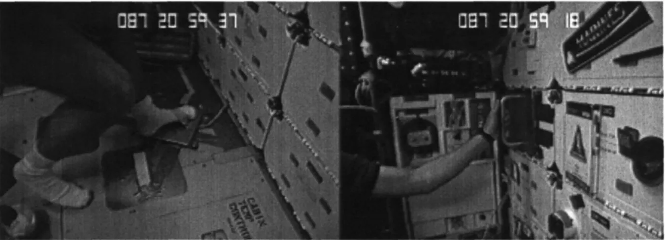
Despite its large pressurized volume, the module is cramped with equipment, giving the astronauts lit-tle space to move in as is evident in Figure 2.2, which shows the interior of the Priroda module.
Figure 2.2: The two photographs show the interior of the Mir Priroda module where most of the EDLS
data was taken. The left image is a view towards the end cone with the hatch in the foreground. The right image is a view facing towards the transfer node. For reference, the microgravity glovebox is shown in both pictures (NASA Mir-21/22 H-8mm Onboard Video ID#53, NASA Image xxx).
2.2 The International Space Station
The International Space Station (ISS) is the largest international civilian scientific and technological project that has ever been undertaken. Under the leadership of the United States, sixteen
nations-USA, Russia, Japan, Canada, Germany, France, Italy, United Kingdom, Belgium, Denmark, Nether-lands, Norway, Spain, Sweden, Switzerland, and Brazil-are building a multi-billion dollar orbiting research facility [51].
2.2.1 Historical Perspective
America's first space station was Skylab. Originally, NASA planned to send ten missions to the moon, but because of more pressing national concerns, Apollo 18, 19, and 20 were cancelled. One of the three Saturn rockets intended for the flight was kept in flight-ready status, while the others were made museum exhibits.' The third stage of the flightworthy booster was modified into Skylab by converting the gigantic fuel tank into cabins. Skylab was launched into orbit on May 14, 1973 on top of a smaller Saturn rocket left over from the Apollo test program. The 75-ton station provided very generous quar-ters for the crew-the main work area was a cylinder 14.7 m long and 6.6 m in diameter. The cylinder
I. The two unused Saturn boosters are located at the Johnson Space Center in Houston, Texas and at the Marshall Space Flight Center in Huntsville, Alabama, respectively.
Section 2.2: The International Space Station was partitioned with a grid made with triangular gaps, so that the astronauts could anchor themselves by pushing toggles on the soles of their boots into the holes. Skylab hosted three crews each with three astronauts for a total 171 days. The first manned mission lasted 28 days, the second 59 days, and the third 84 days. The station had been abandoned for five years when it reentered the atmosphere com-pletely uncontrolled on July 11, 1979 [36].
The Space Transportation System or STS is NASA's name for the collective Space Shuttle Program. On April 12, 1981, the agency launched the first Space Shuttle, Columbia, into orbit. Since that time a fleet of space shuttle orbiters has served a dual role. It is both a transportation system bringing satel-lites and other payloads into orbit and a platform for short-duration microgravity experiments. Since 1992, NASA is transitioning from Shuttle-based research to International Space Station research. It is doing it in three phases: Phase I, the so-called Shuttle-Mir Program, is a cooperation with Russia involving crew exchanges that has been concluded successfully in June 1998. Phase II is the establish-ment of the initial capability for long-term research on ISS with the on-orbit assembly of U.S. and Russian modules while Phase III will expand the station's infrastructure through the addition of hard-ware from all international partners. Details on the three phases are provided in Section 2.2.3 and Section 2.2.4.
The origin of ISS dates back to January 25, 1984 when U.S. President Reagan announced in his State of the Union speech support for a permanent human tended space station intended for completion in the early 1990s. Only days before the address, he had sent private memos to European, Japanese, and Canadian leaders inviting them to join the project. In 1988, the project was named Space Station
Free-dom (SSF). From 1984 until 1992, NASA spent $8 billion on a complex series of design reviews, but
no elements of the station were completed [36].
Due to large budget constraints, poor management, and the inability to meet schedules, SSF was sub-ject to heavy criticism. On March 9, 1993, President Clinton declared a 90-day ultimatum to redesign the station to reduce costs and asked for three station design options, costing $9 billion, $7 billion, and $5 billion respectively. An advisory panel under the chairmanship of MIT President Dr. Charles M. Vest, presented A, B, and C options to the administration. While options A and B were scaled-down versions of SSF, Option C represented a complete departure from the Freedom concept. President Clinton decided for an amalgam of Option A and B. The recommendation of the Vest Committee to bring Russia into the project, led to the signing of a major agreement between the two countries in
Chapter 2: Space Stations and Microgravity
September of 1993. In response, the name of the project was changed to International Space Station Alpha (ISSA) and later to International Space Station (ISS) [36].
Although the ISS design stems largely from the work done for Space Station Freedom, there are sev-eral major design differences between SSF and ISS. Most of these were due to the fact that the orbital inclination for the station and hence the solar beta angle was changed. The solar beta angle is defined as the angle between the orbital plane and the ecliptic. Its maximum value is the sum of the inclination and the tilt of the Earth's equator with the ecliptic (23.50). The fundamental effect of the beta angle is the amount of sunlight received by the spacecraft during a given orbit.
The inclination of the SSF orbit, 28.50, was determined by the latitude of the Kennedy Space Center launch site. Once, Russia became a partner in the station, it was necessary to change the orbit since an inclination of 28.50 made it difficult to reach the space station when launching from the Baikonur Cos-modrome, located at a latitude of 45.90. Therefore, driven by the Russian launch site, an inclination of 51.60 was chosen.2 The beta angle varies with time of the year and orbital precession effects. For the SSF design, the solar beta angle would have varied from -520 to +520, while for the ISS it will vary from -75' to +750 with a frequency of approximately four cycles per year and an average angle of approximately 300. One example of a resulting effect is that during early station assembly, not enough power will be available during high beta angles. A positive effect for the microgravity environment is the fact that at large solar beta angles, the frontal area of the photovoltaic arrays is dramatically reduced, which decreases the drag acceleration levels [37], [61].
2.2.2 Purpose, Objectives, and Organization of ISS
The main purpose of the station has been stated as:Provide an Earth orbiting facility that houses experiment payloads, distributes resource utili-ties, and supports permanent human habitation for conducting research and science experi-ments in a microgravity environment [42].
Based on this purpose, specific objectives were declared, which can be formulated as follows [37]:
* Develop a world-class orbiting laboratory for conducting high-value scientific research.
* Provide access to microgravity resources as early as possible in the assembly sequence.
Section 2.2: The International Space Station
* Develop the ability to live and work in space for extended periods.
* Develop an effective international cooperation.
* Provide a testbed for developing 21st century technology.
Early on, it was decided that designing and building the station was to be the responsibility of a single prime contractor. In August 1993, following the change from SSF to ISSA, The Boeing Company was selected as the prime contractor and in January 1995, NASA and Boeing's Defense and Space Group, Missiles and Space Division signed a $5.63 billion contract for the design and development of the sta-tion. Under the agreement, Boeing is responsible for the integration and verification of the Interna-tional Space Station system and the design, analysis, manufacture, verification and delivery of the U.S. on-orbit segments of the station [53]. Within NASA, the Johnson Space Center (JSC) was selected as the lead center for ISS [36].
Besides, NASA and Boeing, the ISS Program consists of [37]:
* Russian Space Agency (RSA) with its contractors Rocket Space Corporation Energia (RSC-E) and Krunichev Space Center (KhSC)
* Canadian Space Agency (CSA) with its contractor Spar Aerospace
* National Space Development Agency of Japan (NASDA) with its contractor Mitsubishi Heavy Industries
* European Space Agency (ESA) with its contractor Daimler-Benz Aerospace
2.2.3 Phase
I:
The Shuttle-Mir Program
In 1992, the United States signed an agreement with Russia to allow long-duration space flights of
U.S. astronauts on Mir, the flight of a Russian cosmonaut on a Space Shuttle mission, Shuttle/Mir
dockings, and joint science programs. In September 1993, U.S. Vice President Gore and Russian Prime Minister Chernomyrdin announced a further expansion of the human space flight cooperation of the two countries. The implementation consisted of three phases of which the Shuttle-Mir Program was the first [36].
The four primary objectives of Phase I are [30]:
1. To reduce the technical risk associated with the construction and operation of the International
Chapter 2: Space Stations and Microgravity
2. To reduce scientific risk and enhance long duration experiment performance and science utilization
for the ISS.
3. To combine international space operations and joint space technology demonstrations.
4. To provide early opportunities for extended scientific, technologic and engineering research and testing.
These objectives were achieved primarily by an exchange of crews; joint ground control operations; the docking of the Shuttle with Mir to assist in crew exchange; resupply and payload activities; the exchange of personnel to develop an understanding of each space agency's design, development, test, and training, and operational philosophies. Phase I began with Shuttle flight STS-60 in February of 1994, which carried Russian cosmonaut Sergei Krikalev along with five U.S. astronauts into orbit. Altogether, the Shuttle-Mir Program had seven astronauts on Mir, involved 10 Shuttle flights to Mir, 9 dockings, and the delivery of 9 payloads such as a docking module (to simplify docking between Mir and the orbiter), replacement solar panels, food, clothing, experiment supplies, and spare station equipment. Table 2.2 lists the NASA missions to Mir.
Table 2.2: U.S. Astronauts on the Russian Space Station Mir [40], [47]
Length
Mission Astronaut Launch Landing of Stay
NASA 1 / Mir 18 Norman Thagard March 14, 1995 July 7, 1995 114 on Soyuz TM-21 on STS-71 days NASA 2 / Mir 21 Shannon Lucid March 22, 1996 September 26, 1996 188
on STS-76 on STS-79 days
NASA 3 / Mir 22 John Blaha September 16, 1996 January 22, 1997 132
on STS-79 on STS-81 days
NASA 4 / Jerry Linenger January 12, 1997 May 24th, 1997 132
Mir 22 / Mir 23 on STS-81 on STS-84 days
NASA5 / Michael Foale May 15, 1997 October 6, 1997 142
Mir 23 / Mir 24 on STS-84 on STS-86 days
NASA 6 / Mir 24 David Wolf September 25, 1997 January 25, 1998 120
on STS-86 on STS-89 days
NASA 7 / Andrew Thomas January 22, 1998 June 7, 1998 127
Mir 24 / Mir 25 on STS-89 on STS-91 days
With the return of Andrew Thomas from Mir, the most visible part of the Shuttle-Mir Program has been concluded. From August until November 1998 one more Soyuz flight and two more flights of Progress-M unmanned ferries to Mir are planned before the official completion of Phase I. [40]
Section 2.2: The International Space Station
The science program of Phase 1 included scientific research from many disciplines. The microgravity research emphasized the characterization of the microgravity (acceleratory and vibrational) environ-ment, but also included a select amount of research involving protein crystal growth, cell culturing, and some combustion science and fluid physics experiments.
As part of the technology and system validation, several technologies and subsystems for ISS were tested. The main area of interests were systems engineering and crew support.
Systems engineering tests performed to validate designs fell into the following categories: (1) Life Support, (2) EVA Technology, (3) Vibration Isolation / Microgravity Environment, (4) Assembly and Maintenance, (5) Loads and Dynamics, (6) Data Processing System, (7) Contamination and Radiation, (8) Micrometeoroid/Orbital Debris [40].
Standards for crew support were established in the following areas: (1) Medical Support, (2) Habitation, (3) Environmental and Advanced Life Support [40].
Some tests and experiments led to specific design enhancements and modifications to ISS. For exam-ple, evaluation of docking and rendezvous maneuvers of the Shuttle with Mir, led to a placement of additional lighting of the Space Station to enable use of the orbiter's star trackers during proximity operations [52].
The Enhanced Dynamic Load Sensors Experiment was conducted within Phase 1 as a so-called risk
mitigation experiment. Its results, to be discussed in Chapter 5, are leading to changes in the
specifica-tions for space station windows and possibly other components.
2.2.4 ISS Phases
II
and III
As was mentioned earlier, the second and third phases of the International Space Station program con-stitute construction and operation of the station. According to Revision D of the Assembly Sequence from May 31, 1998, construction of ISS will require approximately 50 flights (excluding resupply and logistics flights) over a period of more than five years [19], [49]. U.S. flights dedicated to assembly are referred to as "A" flights (e.g., 12A) and Russian assembly flights as "R" flights (e.g., 2R). Flights involving the transportation of science experiments to the station are called utilization flights (e.g., Flight UF3). Labels "J" and "E" indicate flights involving Japanese and European hardware respec-tively [37].
Chapter 2: Space Stations and Microgravity
The first element of ISS to be lifted into orbit is the Russian-built Control Module or Functional Cargo Block with the Russian acronym FGB. It is currently scheduled to be launched aboard a Russian Pro-ton Rocket in November 1998 as Flight 1AIR. The FGB, named in May 1998 Zarya ("Sunrise"), is a self-supporting module with propulsive control, fuel storage, rendezvous, and docking capability [50], [56]. The second component (Flight 2A) in orbit will be the Unity node built by Boeing. The node will be mated with the FGB and serve as a connector for future modules [55]. The third component of ISS will be the Service Module, which is the primary Russian station contribution. The module will pro-vide life support for all early elements and initial living quarters. After the attachment of a Soyuz cap-sule as an assured crew return vehicle for emergencies in July 1999, the first crew will begin to live on ISS [50]. The U.S. Laboratory Module will be brought to the ISS in October of 1999 (Flight 5A). This element will provide equipment for research and technology development and house all the necessary systems to support a laboratory environment and control the U.S. segment of the ISS. Phase II of the ISS Program is expected to be concluded in January 2000. Phase III involves completing the assembly and operation of the station therafter. The station is expected to be completed January 2004 [19].
The ISS is comprised of the following seven segments:
1. United States On-orbit Segment (USOS)
The U.S. modules making up the USOS are the U.S. Laboratory and the U.S. Habitation Module.
2. International Ground System
3. Attached Pressurized Module (APM)
The APM is also called the Columbus Orbital Facility (COF) and is analogous to the U.S. Labora-tory. It is being supplied by the European Space Agency.
4. Japanese Experiment Module (JEM)
5. Russian Segment (RS)
Russia is furnishing the Service Module (SM) and two Research Modules.
6. Mini-Pressurized Logistics Module (MPLM)
The MPLM is built by the Italian Space Agency (Agenzia Spaziale Italiana, ASI) and its contractor Alenia for NASA under a subcontract.
7. Mobile Servicing System (MSS)
Section 2.2: The International Space Station
I
I
I
I
Figure 2.3:
The figure shows the components making up the International Space Station and the country or agency responsible for it [59].Chapter 2: Space Stations and Microgravity
Figure 2.3 shows how the components of the space station will be assembled. As can be deduced from the above description, ISS consists not only of on-orbit hardware but includes also ground facilities. The on-orbit Space Station and portions of the Space Station Ground Segment will be linked via the Tracking and Data Relay Satellite System (TDRSS) for audio, video, data, and command communica-tions. For the purpose of this thesis, the term "space station" or "ISS" will imply the on-orbit compo-nent only. The space station will operate as an integrated vehicle with an integrated crew, a single commander, and English as the language of operations [37].
It is planned to have the following characteristics once completed [59]:
* Volume: 1,200 cubic meters at a pressure of 101 kPa (14.7 psi)
* Total mass: 456,000 kg
* Dimensions (including solar panels): 108.6 m by 79.9 m
* Maximum power output: 110 kW
* Orbital inclination: 51.6'
* Average orbital altitude: 407 km (220 nmi)
* Crew: up to seven (three until assembly is complete)
Figure 2.4 shows the International Space Station once completed.
The pressurized living and working space aboard the completed ISS will be roughly equivalent to the passenger cabin volume of two Boeing 747 jetliners or about three times more than on Mir. Figure 2.5 shows the interior of the U.S. Laboratory mock-up at the Johnson Space Center. As is evident from the photographs, the astronauts will have much more volume to move about than on Mir.
2.3 The Microgravity Environment
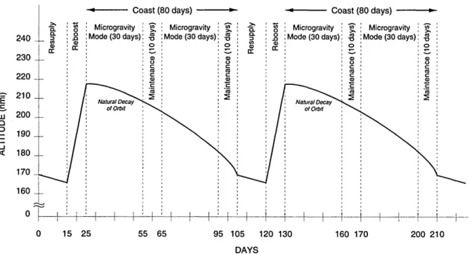
With the exception of the Apollo moon missions, manned spacecraft operate in low-Earth orbit, which implies altitudes from about 100 to about 600 km. In the case of the International Space Station, the altitude will vary from 300 to 400 km (see Figure 2.6 on page 47). The discussion of the microgravity environment in this section deals exclusively with the situation on manned spacecraft in LEO.
Section 2.3: The Microgravity Environment
'-9
Figure 2.4: This computer-generated image shows
complete [57].
the International Space Station when assembly is
Chapter 2: Space Stations and Microgravity
The absence of a gravity effect is called weightlessness, free fall, or zero-g. In Earth orbit, the effect arises from Earth's gravitational pull being compensated by a centrifugal force due to a forward (or tangential) velocity large enough such that the distance from the center of the Earth remains constant.
In practice, zero-g cannot be achieved, since an orbiting spacecraft is subject to various small forces produced by the space environment. As a result, for most practical applications in LEO, the gravita-tional effect can be reduced to 10-6 g (=1 pg); a level of 10- 7 g can be achieved over a very small region near the center of mass of the spacecraft. For this reason the term microgravity (pg) rather than zero-g is best to describe the condition in orbit properly.
2.3.1 Classification of On-Orbit Disturbances
The spacecraft environment on typical manned spacecraft during orbital flight is disturbed by a num-ber of different accelerations and vibrations. The accelerations experienced on orbit are classified fun-damentally as: (1) Quasi-steady or residual accelerations and (2) Non-steady accelerations.
2.3.2 Quasi-steady Accelerations
Quasi-steady or residual accelerations are due to external forces acting on the spacecraft and deter-mined by the external configuration of the vehicle and the parameters of the orbit. By their nature these accelerations act for long periods of time. They are usually defined as accelerations with frequencies below 0.01 Hz, which uncouples the quasi-steady state environment from the vibratory environment since that limit value for the frequency is generally an order of magnitude less than the first structural mode. Calculations of the quasi-steady state microgravity environment are based on rigid-body dynamics.
Assuming a circular orbit and a local rotating frame attached to the spacecraft, the equation defining the quasi-steady state accelerations can be written as:
S rcm
a =aenvironment - IL -rc ) - OX(OX rp_ .cm) -- OXrpcm (2.1)
where aenvironmentis the acceleration due to the environment, p. = GM = 3.986x10¹⁴ m3 / S2 is
Earth's gravitational constant, rp is the vector from the center of the Earth to a point p on the station, rcm is the vector from the center of the Earth's to the station center of mass, and rp - cm is the vector from the station center of mass to the point of interest. The quantity to is the station's rotational rate
Section 2.3: The Microgravity Environment
vector whose three components are wx, (Oy - n), and oz- The variables wx, oy, and wz are the sta-tion's Euler rates and n is the angular orbit rate, which assumed to be positive.
The first term of Eqn. (2.1), is the acceleration vector caused by the external environment, the second term is the gravity gradient acceleration acting on a point that is a distance rp _ cm from the center of mass, the third term is the centripetal acceleration, and the fourth term is the tangential acceleration. Each term is discussed below.
Environmental Forces
The first term of the equation encompasses all the accelerations induced by the external environment, such as aerodynamic drag, solar pressure, quasi-steady impact of ambient micrometeoroids, tidal forces due to the Earth-moon orientation. The largest contributor to the environmental acceleration is drag. The acceleration due to drag is represented by:
1 , RA + R P '2
adrag - CDAp( (02 (2.2)
arg 2m t"DtP•' 2
where m is the mass of the station, CD the drag coefficient, A the cross-sectional area, p the air den-sity, ((RA + Rp) / 2)2 is the square of the semi-major axis of the orbit expresssed in terms of the apo-gee and periapo-gee radii, and w the angular velocity in orbit [63].
For the Mir space station, the acceleration due to aerodynamic drag has been estimated to be less than 2x10- 5 g (prior to the docking of the Spektr and Priroda module), while the more aerodynamic Shut-tle orbiter, experiences an acceleration of approximately 1 to 5x10 6 g [12].
Gravity Gradient Acceleration
At the center of mass of the spacecraft in orbit, the centrifugal acceleration cancels out Earth's gravita-tional acceleration. All other points experience a slightly smaller or larger gravitagravita-tional acceleration but are constrained in their path since the spacecraft is a rigid body. As a result, a spatial separation from the center of mass, induces a gravity gradient acceleration. This acceleration is the main contrib-utor to the acceleration magnitude sensed by a payload aboard the ISS.
Chapter 2: Space Stations and Microgravity
Reference [61] gives the following equations for the gravity gradient accelerations in the x, y, and z direction:
aGGx
(7
' GGy =-(
aGGz •3 (2.3)
GGxcm cm cm
As the equations show, the gravity gradient induced acceleration along the z or nadir direction is twice as large as the x or flight path direction and the y direction. For example, for a station orbital altitude of 407 km (220 nmi), a I pg acceleration will be experienced at a distance of 4.11 m in the z direction and 8.22 m in the x and y directions from the center of mass [61].
Centrifugal Acceleration
There are two rotation-induced accelerations disturbing the microgravity environment. They are non-physical forces; they arise from kinematics and are not due to non-physical interactions. The first of them is the centrifugal acceleration. For a perfectly nadir-pointing vehicle, the nominal centrifugal accelera-tion is caused by the once-per-orbit rotaaccelera-tion required for an Earth pointing attitude. In this case, the nominal centrifugal acceleration vector lies in the orbit plane normal to the angular momentum vector. Most spacecraft are pointing towards Earth for communication, observation, and other reasons. To eliminate thie centrifugal contribution to the acceleration environment, the vehicle would have to be inertially-oriented [61], [63].
Tangential Acceleration
The tangential acceleration is caused by the angular acceleration experienced by a rigid body. The angular acceleration arises from a change in direction of angular rates from nominal angular rotation.
2.3.3 Non-Steady Accelerations
Non-steady accelerations are generated within the spacecraft. These disturbances can either be
oscilla-tory or transient (i.e., spikes) due to singular events. Oscillaoscilla-tory accelerations (i.e., vibrations) are
those that are periodic in nature with a characteristic frequency ranging from a tenth of a Hertz to sev-eral hundred Hertz. Sources for these disturbances are reciprocating pumps, fans, valves, motors, gyros, antenna dither motion, and acoustic noise from sources such as fans, duct inlets and outlets, pumps, and blowers. For example, the Space Shuttle orbiter has a refrigerator/freezer with a pump that causes significant vibrations at 22 Hz [3]. While, a single source of disturbances may not be signifi-cant, if multiple sources are superimposed, the effect can be substantial.
Section 2.3: The Microgravity Environment
The transient accelerations have typically durations of less than a second and are nonperiodic. The energy in the disturbance is typically spread across the frequency range from the sub-Hertz to the hun-dreds of Hertz range. The Space Shuttle orbiter for example has several structural modes in the 1 to 10-Hz frequency regime which are often excited by transient accelerations. Origins for these disturbances are thruster firings, satellite launches, docking impacts, robotic arm motion, and of course various crew activities.
2.3.4 Measurements of the Microgravity Environment
As interest in microgravity for research grew, so did interest to quantify the acceleratory environment. On the Soviet Salyut station, instruments originally intended for other measurements, were used to determine the spacecraft's steady-state acceleration environment. Examples of these instruments were triaxial magnetometer, solar and stellar photometers, and angular motion transducers [12].
First a geophone was used to measure non-steady accelerations, then, beginning in 1980, a triaxial accelerometer package (IMU). In a "Resonance" experiment, all non-critical equipment was shut down to create the baseline quiescent environment, which was then compared with the acceleratory environment during standard operation. The IMU results are summarized in Table 2.3.
Table 2.3: Typical
Maximum Acceleration Levels onSalyut-7 Space
Station [12]Maximum Acceleration [g]
Activity x Direction y Direction z Direction
Unmanned Spacecraft 10-5 10-5 10-5
Standard Crew Activities 2x10- 4 to 2x10- 5 10- 3 to 10- 5 10- 3 to 10- 5 Crew Exercise (tread mill) 10- 4 8xl0- 3 8xl0- 3
In 1992, as part of the Russian-French Mission Antares on Mir, two sets of microacceloremeters devel-oped by the French were installed on the Russian orbital complex. The devices measured accelerations over a range of +/- 100 mg with a bandwidth of 0.1-400 Hz and a resolution of 5x10- 5 g per axis. The Resonance experiment from Salyut was repeated with the French microaccelerometers on Mir and the data from the quiescent condition compared to the time when a crew member was exercising on the treadmill. A general increase in acceleration levels across the measured frequency range was observed with an additional peak at 4 Hz, which was attributed to the cycling frequency on the treadmill [12]. During the first years of Space Shuttle flights, science experiments which were most sensitive to accel-eration levels, incorporated their own accelerometers to determine the microgravity conditions. In

![Figure 2.3: The figure shows the components making up the International Space Station and the country or agency responsible for it [59].](https://thumb-eu.123doks.com/thumbv2/123doknet/14678763.558700/35.918.168.765.151.979/figure-figure-components-making-international-station-country-responsible.webp)
![Figure 2.5: The photographs show the mock-up of the U.S. Laboratory at the Johnson Space Center [69].](https://thumb-eu.123doks.com/thumbv2/123doknet/14678763.558700/37.918.127.801.689.970/figure-photographs-mock-u-laboratory-johnson-space-center.webp)
![Figure 2.7: ISS microgravity acceleration limits. RMS acceleration magnitude in 1/3 octave bands aver- aver-age over 100 seconds [60].](https://thumb-eu.123doks.com/thumbv2/123doknet/14678763.558700/48.918.190.751.157.422/figure-microgravity-acceleration-limits-acceleration-magnitude-octave-seconds.webp)
![Figure 3.1: The photograph shows the set up of the Skylab CrewNehicle Disturbance Experiment set-up in the Skylab Orbital Workshop [35].](https://thumb-eu.123doks.com/thumbv2/123doknet/14678763.558700/56.918.128.802.231.802/figure-photograph-skylab-crewnehicle-disturbance-experiment-orbital-workshop.webp)
![Figure 3.2: The figure shows the average and maximum forces measured for a set of activities during the Skylab CrewNehicle Disturbance ExperimentT-013 in 1973 [25].](https://thumb-eu.123doks.com/thumbv2/123doknet/14678763.558700/58.918.155.773.161.608/figure-average-maximum-measured-activities-crewnehicle-disturbance-experimentt.webp)