HAL Id: hal-01712940
https://hal.archives-ouvertes.fr/hal-01712940
Submitted on 27 Feb 2018
HAL is a multi-disciplinary open access
archive for the deposit and dissemination of
sci-entific research documents, whether they are
pub-lished or not. The documents may come from
teaching and research institutions in France or
abroad, or from public or private research centers.
L’archive ouverte pluridisciplinaire HAL, est
destinée au dépôt et à la diffusion de documents
scientifiques de niveau recherche, publiés ou non,
émanant des établissements d’enseignement et de
recherche français ou étrangers, des laboratoires
publics ou privés.
Cooperative Lifting and Transport by a Group of Mobile
Robots
Bassem Hichri, Lounis Adouane, Jean-Christophe Fauroux, Youcef Mezouar,
Y Doroftei
To cite this version:
Bassem Hichri, Lounis Adouane, Jean-Christophe Fauroux, Youcef Mezouar, Y Doroftei.
Coopera-tive Lifting and Transport by a Group of Mobile Robots. International Symposium on Distributed
Autonomous Robotic Systems, DARS 2014, Nov 2014, Daejeon, France. �hal-01712940�
of Mobile Robots
B.Hichri1, L. Adouane2, J-C. Fauroux3, Y. Mezouar4and I. Doroftei5
Abstract This paper addresses cooperative manipulation and transportation of any payload shape, by assembling a group of simple mobile robots (denoted m-bots) into a modular poly-robot (p-bot). The focus is made in this paper on the chosen methodology to obtain sub-optimal positioning of the robots around the payload to lift it and to transport it while maintaining a geometric multi-robot formation. This appropriate positioning is obtained by combining the constraint to ensure Force Clo-sure Grasping (FCG) for stable and safe lifting of the payload and the maximization of the Static Stability Margin (SSM) during the transport. A predefined control law is then used to track a virtual structure in which each elementary robot has to keep the desired position relative to the payload. Simulation results for an object of any shape, described by a parametric curve, are presented. Additional 3D simulation results with a multi-body dynamic software validate our proposal.
Key words: Cooperative mobile robots, Payload co-manipulation and transport, Force closure grasping, Static stability margin, Control architecture.
1 Introduction
In recent years, many researches were oriented to survey and design collaborative mobile robotic systems [29, 26] gathering different engineering and science disci-plines. This blend between those disciplines allows the design of autonomous sys-tems able to interact with the environment without human mediation and also to achieve diverse complex tasks or infeasible by humans, such as exploring dangerous and/or unreachable areas [7] or navigation in formation for a group of autonomous robots [1]. Autonomous mobile robots have the ability for sensing and reacting in
1Institut Pascal Clermont Ferrand, France, e-mail: Bassem.Hichri@ifma.fr 2Institut Pascal C-F, France, e-mail: Lounis.Adouane@univ-bpclermont.fr 3Institut Pascal C-F, France, e-mail: Jean-Christophe.Fauroux@ifma.fr 4Institut Pascal C-F, France, e-mail: Youcef.Mezouar@univ-bpclermont.fr 5Gh. Asachi Tech. Univ. of Iasi, Romania, e-mail: idorofte@mail.tuiasi.ro
2 B. Hichri, L. Adouane, J-C. Fauroux, Y. Mezouar and I. Doroftei
the environment by acquiring additional abilities. They can also collaborate when a task needs more than one robot, such as heavy objects co-manipulation or transport [2, 7, 13, 22]. The aim of our research is to co-manipulate and to transport objects using a group of mobile robots. We aim to design an innovative architecture for payload transport on structured environment. Collaborative robots behaviors may be also interesting for transporting tasks with mobile robots. Many robotic examples can be mentioned such as in [4, 13, 19, 23, 32]. Our goal in the C3Bots project (Col-laborative Cross and Carry mobile roBots) is to design several mobile robots with a simple mechanical architecture called m-bots that will be able to autonomously co-manipulate and transport objects of any shape by connecting together. The resulting poly-robot system, called p-bot, will be able to solve the so-called removal-man-task to transport object of any shape and mass repartition. Reconfiguring the p-bot by adjusting the number of m-bots allows to manipulate heavy objects with any shape, particularly if they are wider than a single m-bot. During the manipulation, the grasping task [3, 31] is a crucial phase for payload lifting and if it fails the whole task cannot be achieved.
To ensure the co-manipulation task, he group of m-bots must succeed to ensure the payload Force Closure Grasping (FCG) [3, 11, 20, 24, 31, 36] until putting it on their top platform. FCG refers to Newton laws which allows to ensure the payload immobility [31]. In the aim of ensuring object stability, which is the goal of any used grasping strategy, several methods have been developed using various approaches. Avoiding too large forces allows to reduce the power for the manipulator’s actua-tion and the deformaactua-tion of the manipulated object. A grasp is considered stable when a miniature disturbance on the position of the manipulated object or contact force, generates a restoring wrench that brings the system back to a stable config-uration [3]. In [14], Nguyen presents an algorithm for stable grasps construction and he proved the possibility of making stable all 3D force closure grasps. Accord-ing to [3, 31], a graspAccord-ing strategy should ensure stability, task compatibility and adaptability to novel objects. Analytical and empirical approaches were developed in different literatures to ensure a stable grasping. The former approach choose the manipulator configuration and contact positions with kinematical and dynamical formulation whereas empirical approaches use learning to achieve a grasp depend-ing on the task and on the geometry of the object. Diverse analytical methods were developed to find a force closure grasp [11, 20, 36]. The latter approach avoids the complexity of computation by attempting to mimic human strategies for grasping. Datagloves and map human hand were used by researchers for empirical approaches to learn the different joint angles [25, 30], hand preshape [16]. Vision based ap-proach is also used to demonstrate grasping skills. A robot can track an operator hand for several times to collect sufficient data [10, 27].
Payload stability during movement is evaluated according to developed metrics in literature. In the late sixties, stability margin metrics were developed and classi-fied mainly in two categories: static [28]-[12] and dynamic [15]-[8] stability mar-gins. We consider the Static Stability Margin (SSM) since our system evolves at low speed in a structured environment. This margin was defined by McGhee and Frank [28] as follows: ”static stability margin is the shortest distance from the vertical
pro-jection of the centre of gravity to any point on the boundary of the support pattern”. Considering the payload lifting and transport using mobile robots, stability is also ensured by coordinating the group of transporting robots which means multi-robot control problem. The multi-robot navigation in formation is the main research area linked to the phase of payload transportation. A multitude of control architecture to deal with this task were proposed in the literature [1, 21, 34]. A multi-robot system control can be either centralized or distributed. The control problem is discussed to provide a suitable control strategy for this task. Formation control can be classified according to recent literature, [1, 34], into three main approaches: the behavior-based approach, the leader-follower approach and the virtual structure approach.
This paper presents an algorithm allowing to determine an optimal positioning of m-bots around a general payload in order to maximize the Static Stability Margin (SSM) and to ensure Force Closure Grasping (FCG). A centralized control will be used for its higher calculation performances to calculate different desired positions according to a payload of any shape. For targets reaching and payload transport, the groups of robots will act according to centralized control approach. A predefined control law is then used to track a virtual structure in which each elementary robot has to keep the desired position relative to the payload. This paper is organized as follow: in Section 2 the paradigm of C3Bots project is introduced and the general
problem is presented for co-manipulation and transport using multi-robot system; Section 3 will present the robots positioning according to both criteria SSM and FCG computation and the multi-robot transport strategy. Simulation results for an object of any shape, described by a parametric curve, and 3D simulations with a multi-body dynamic software are also presented. Finally Section 4 provides a con-clusion and future works.
2 Paradigm and problem statement
The paradigm of C3Bots project is to co-manipulate and transport a common pay-load through collaboration between several similar elementary robots (see Fig. 1). Wheeled robots were selected for their versatility on various terrains and good effi-ciency on regular grounds compared to legs and tracks. The C3Bots transport
strat-egy takes inspiration from Army Ants [19] by laying the payload on top of robot’s bodies, and from the structure given in [23], that has a rotative arm on top of it. The concept of modularity was also kept and each m-bot is built from two parts: a mobile platform and a manipulation mechanism [5]. The mobile platform is a single-axle Khepera robot and the manipulator is fixed on a rotary platform that lets the robot turn freely on itself when the object lays on the transporting platform. The manipu-lator has a parallelogram structure to bring the payload from the ground to the m-bot top platform with a circular trajectory [6].
The resulting p-bot system (cf. Fig. 1(a), Fig. 1(c)) is thus allowed to translate along any direction and rotate around any point in the ground plane. Before starting the transport task, the m-bots have to achieve the co-manipulation process using the mechanism presented in [5] and detailed in [6]. Its role is to hold firmly the payload
4 B. Hichri, L. Adouane, J-C. Fauroux, Y. Mezouar and I. Doroftei
(a) Prototype for object lift-ing and transport [5]
(b) Payload prehension by two m-bots
(c) Payload lifted by two m-bots
⃗
z
m+1f
tpmµ
2f
npmf
ngmf
tgmµ
1 ⃗ xm Gi ⃗ ym⃗
x
m⃗
z
mC
m , g(
µ
g)
C
m+1, g(
µ
g)
f
m+1, g , n Cm+1, p(µp)f
m+1, g ,tf
m , g ,nf
m , g ,tf
m , p , tf
m+1, p , t fm , p , n Cm , p(µp) fm+1, p , n⃗
x
m+1G
m +1f
ngmm∈{1,....,mmax} : m-bot number,
j∈{p,g}:contact location payload/ground
G
pG
mµg : friction coefficient with ground
µp : friction coefficient with payload k∈{n,t}:normal, tangential
end −effector motion
Forward motion of m−bots
(d) Two M-bots pushing on the payload to elevate it with parallelogram manipulator [6] Fig. 1 Co-manipulation of a box by a group of m-bots
and to ensure FCG [24] to lift the object by applying a sufficient normal force fm,p,n
(see Fig. 1(d) and Fig. 4) with:
fm,p,n∈ [0, fmax] = [0, µpµgmrg] (1)
The value of fmax is obtained while applying the well known resultant of the
force/moment for the all system (First and Second principle of Newton). We ob-tained thus a simple formulation of fmaxwhile taking into account: µpthe
payload-end-effector friction coefficient; µgthe wheel-ground friction coefficient; mmis the
robot mass and g is the gravity.
The minimum number mminof m-bots that have to be used to lift and transport
the payload is obtained according to the following equation:
mmin
∑
m=1
fm,p,t= Mplg (2)
3 Cooperative mobile robot manipulation and transport
The proposed overall cooperative manipulation and transport strategy, for any pay-load shape, by a group of m-bots is presented in Figure 2. This figure gives the most important steps to be achieved during this cooperative task. The details of the cho-sen criteria for cooperative manipulation and transportation are given respectively in sub-sections 3.1 and 3.2.
Step 1 (cf. Fig. 2) presents the first phase of the task and which consists on pay-load detection and estimation of its mass and gravity center position. Step 2 consists on determining the minimum number mmin of m-bots that could be used to ensure the payload lifting and transport with relative to (2). Step 3 presents the main con-tribution of this paper. It is detailed by the flowchart in the right side of Fig. 2 and will be discussed in sections 3.1.1 and section 3.1.2. Sasaki in [18] treated a similar problem for optimal robots positioning taking into account two criterion: the pay-load stability and the energy consumption. It was considered that the positioning is optimal when the payload is stable and the robots consume the minimum of energy (according to the data received from the robots sensors). In the proposed strategy, the m-bots positioning is optimal when FCG and SSM are ensured. Finally, Step 4 corresponds to multi-robot transport the payload toward the assigned final pose, this part will be detailed in section 3.2.
The configuration ensures FCG Obtaining of the minimum number of
m-bots to lift the payload (cf. Eq. 2)
Generate the initial grasp (it=1) that ensures a SSM (cf. Eq. 4) The configuration ensures SSM The SSM value is higher than the previous value
Change the grasp configuration ensuring SSM (cf. Eq. 4)
Save the grasp configuration
it<itmax Return the last saved
configuration yes no no no no yes yes yes
Payload detection and estimation of
Mpl and Gpl
Determine the appropriate m-bots configuration
Go forward to the obtained positions
Lift the payload
Transport the payload toward a final configuration while keeping
a specific formation Step 1 Step 2 Step 3 Step 4 Step 3
6 B. Hichri, L. Adouane, J-C. Fauroux, Y. Mezouar and I. Doroftei
3.1 Cooperative m-bots positioning and co-manipulation
Since the features of the payload are known (step 1 in Fig. 2) the minimum number of m-bots (mmin) is obtained while using equation 2 (step 2), the group of m-bots
must be well positioned around the payload (step 3) to permit to safely lift it and to maintain a well stability of the payload in the top of the p-bot during the transporta-tion phase (step 4). During this manipulatransporta-tion phase (sub-step 2 in step 4), FCG (cf. sub-section 3.1.1) as well as SSM (cf. sub-section 3.1.2) must be thus ensured to lift and transport safely the object (cf. details given for Step 3 in Figure 2).
3.1.1 Force Closure Grasping
Force closure grasping problem is extensively treated and studied for objects ma-nipulation using multi fingered robotic hand [35, 37]. This problem was adapted to mobile robot co-manipulation and transport in C3Bots project to ensure lifting and transport task. The co-manipulation problem (cf. section 2) is restricted to a 2D problem in plane (O, x, y) while robots are acting simultaneously and applying a tightening forces on the payload on the same plane (Fig. 3).
(a) Side view (b) Top view
Friction cone Cpm Payload m−bot Gpl α fm , p , n
(c) m-bot planar contact Fig. 3 Applied tightening forces on the payload
The aim of this part is to ensure force closure grasping when choosing the m-bots positions which returns to fully constraint the payload motion with mminm-bots. In
other words, the static equilibrium must be ensured while positioning the group of mobile robots. The problem of force closure grasping is studied under the following assumptions (cf. Fig. 3(c)):
• A contact force lies inside the friction cone centred about the normal direction to the contact surface with half angle α.
• The tangent of α represent the friction coefficient. • The friction cone of the mthcontact is denoted C
pm.
A necessary and sufficient condition to have force closure is that the intersection of three friction cones is not empty [36]. This condition was extended to mminm-bots.
problem treated in this paper focuses on co-manipulation using a group of modular mobile robots. The proposed algorithm is based on ensuring force closure if forces and moments equilibrium satisfy (3) and when the payload center of mass is inside the friction cones intersection (4). The later condition allows to reduce the moments generated on the payload by the m-bots because the direction of the applied force on the plane is closer to the gravity center.
mmin
∑
m=1 (PmGpl⊗ fm,p,n) = 0; mmin∑
m=1 fm,p,n= 0 (3) Gpl∈ Convexhull(∩Cpm) |m = 1..mmin (4)Where Cpmpresents the friction cone for the contact force on Pmand fm,p,nis the
applied normal on the payload (cf. Fig. 3(c)).
3.1.2 Static Stability Margin (SSM)
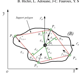
In this part, Static Stability Margin (SSM) is considered to ensure the payload sta-bility during the transporting phase. Stasta-bility margins were extensively studied for walking mobile robots [9, 17, 38]. In C3Bots project, to ensure a stable payload transport, the Static Stability Margin (SSM) is a crucial criterion for a successful task achievement. Before describing the proposed algorithm for m-bots position-ing ensurposition-ing an optimal SSM durposition-ing object transport usposition-ing m-bots, let’s detail the following assumptions (cf. Fig. 4):
• The payload shape from the top view is a closed curve (B) and defined by polar curve defined by P(θ ); θ ∈ [0, 2π].
• In function of the payload mass Mp, mmin is the minimum number of m-bots
allowing to lift and transport the object. • The payload center of mass is denoted Gpl.
Let R(Gpl, xpl, ypl, zpl) be the frame linked to the payload with respect to the
reference frame R(O, x, y, z) (cf. Fig. 4). Cartesian coordinates will be used in the proposed algorithm. As given in section 2, P(θ ) be the parametric description of the payload closed boundary (B). Pm|m=1..mmin are the m-bots positions, Hm,m+1 is
the projection of the payload center of mass G on the edge linking two consecutive points Pm and Pm+1 and dm,m+1 is the stability margin on the same edge. Pm and
Pmmin+1are confounded and as a consequence dm,mmin+1is equal to dmmin,1.
The idea behind the algorithm is to run through (B) and to find the set of points Pmensuring a maximal SSM while maximizing the objective function (5). The
con-straint imposed by (6) must be satisfied for mminm-bots≥3 which gives a necessary
condition to keep the center of mass Gplinside the polygon (P1..Pm)
8 B. Hichri, L. Adouane, J-C. Fauroux, Y. Mezouar and I. Doroftei
⃗ f1, p , n ⃗ f2, p , n ⃗ f4, p , n ⃗ f3, p , n P3 P4 ⃗x ⃗y θ1 ⃗ ypl ⃗ xpl Gpl O P1 P2 H41 H21 H32 d32 d41 d12 P3 P4 ⃗x ⃗y θ1 ⃗ yob ⃗ xob G Dmax O P1 P2 H42 H52 H31 d1 d3 d3 P5 d4 H51 d43 P3 P4 ⃗x ⃗y θ 1 ⃗ yob ⃗ xob G Dmax O P1 P2 H63 d63 d42 d52 P5 d51 d61 H61 P6 E13 H43 H43 H42 H52 H51 H43 E15 E24 E13 E25 E34 E15 E24 E61 E25 E34 E63
(B)
Support polygonFig. 4 Support polygon formed by four robots positioned at Pm|m=1..4
θm+1− θm< π |m = {1...mmin} (6)
In the case where we have only two m-bots to co-manipulate the object, the con-straint expressed by (6) is not considered and the robots are positioned in opposed positions which means θm+1− θm= π. For each configuration where n m-bots ≥ 3,
the algorithm aims at determining the equation of the line PmPm+1and at computing
the shortest distance of Gpl(xGpl, yGpl) from it.
Then dm,m+1 is calculated by (7) which represent the stability margin relative
to each edge and the static stability margin SSM given by (5). Pm coordinates are
expressed in R(Gpl, xpl, ypl, zpl) (cf. Fig. 4). dm,m+1= d(G, (PmPm+1)) = xG yPm+1−yPm xPm+1−xPm− yG+ yPm− xPm yPm+1−yPm xPm+1−xPm r (yxPm+1−yPm Pm+1−xPm) 2+ 1 (7) 3.1.3 Simulation results
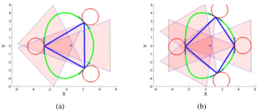
The proposed algorithm allows to determine a sub-optimal configuration for a group of mobile robots in order to lift and transport a payload of any shape. Two criteria have been respected (FCG and SSM) which reduces the total configurations to be tested by the algorithm taking into consideration (3) and (4). The Algorithm was simulated by using an Intel Core i5 2400 CPU 3.1 GHz system. Fig. 5 presents the simulation results for the developed algorithm for robots positioning in order to guarantee an optimal static stability margin respecting the force closure condition. The blue bold polygon presents the polygon of support ensuring the optimal SSM (cf. subsection 3.1.2), the thin blue lines presents the friction cones sides and the intersection is presented by contrasted area resulted by the superposition of friction cones. It is shown how the algorithm keeps the payload center of mass Gplinside the
intersection area and it allows to build a polygon of support ensuring the payload stability during the transport. The duration to find results depends on the chosen steps of θmto run throw the payload curve.
(a) (b)
Fig. 5 Simulation results: a) 3 m-bots positioning; b) 4 m-bots positioning
The payload stability during the lifting phase was simulated with respect to both criteria (SSM and FCG) using ADAMS multi-body dynamic software to validate the proposed algorithm (cf. Fig. 2) while testing the m-bots performances when they are positioned to co-manipulate the object. Fig. 6 shows that the robots ensure the payload lifting without loss of stability of the lift. Videos for simulation are visible under [33].
(a) (b) (c) (d)
Fig. 6 Multibody simulation results with ADMAS software: Top view (a and c), and 3D lifting phase (b and d).
3.2 Multi-robot transport
After lifting the payload, which is positioned now on the top of the p-bot, the group of m-bots must transport the payload toward a final configuration. During this last phase (Step 4 in Fig. 2), and in order to guarantee the payload stability, the p-bot should navigate as rigid formation shape and for this, a virtual structure architecture was used [1]. After the end of Step 3, each m-bot receives its attributed position which insures the sub-optimal p-bot positioning that permits to ensure Force
Clo-10 B. Hichri, L. Adouane, J-C. Fauroux, Y. Mezouar and I. Doroftei
sure Grasping (FCG) and to maximize the Static Stability Margin (SSM) during the transport. For transport task, the m-bots have to reach their goals, computed using the algorithm presented in the previous section (cf. Step 4 in Fig. 2). After reaching the desired positions, the transport task starts considering that the payload lays on robots bodies. To avoid payload slippage, the group of m-bots has to track a fixed position relative to the object when it follows a trajectory. In this section, a control law is proposed to solve the goal reaching problem (Pm in section. 2) and the nav-igation as Virtual Structure (VS) of the set of m-bots. In VS approach [34] [1], the entire formation is considered as a rigid body and the notion of hierarchy do not ex-ist. The control law for each entity is derived by defining the VS dynamics and then translate the motion of the VS into the desired motion of each elementary robot. The main advantages of this approach are its simplicity to prescribe the coordinate behavior of the group and the maintaining of the formation during manoeuvres.
The result of the algorithm for a given object shape described by a parametric curve (B) is a set of n targets to be reached by the m-bots. Considering a unicy-cle mobile robot, the state vector Xm= (xm, ym, θm)T denotes the position of the
mthrobot center of mass Gm(xm, ym) and its orientation θmwith respect to x axis of
the global frame. The m-bots control inputs are the forward velocity V and the an-gular velocity ω. Let e be the error between the m-bot current pose and the desired pose defined by Xdm= (xdm, ydm, θdm)T: e = Xdm− Xm.
After positioning the m-bots, they must keep their desired position (xdm, ydm) with respect to the payload center of mass Gpland must respect the following
con-ditions during the task achievement:
xdm= xG+ lxmcos θdm− lymsin θdm
ydm= yG+ lxmsin θdm+ lymcos θdm
(8)
where lxmand lymare the relative distances GmGpl according the axis x and y
re-spectively. These two distances define rigid links maintaining the robot position with respect to Gpl. The used control law [1] is given by (9):
Vm= Vmax− (Vmax−Vd)e−(d
2 m/σ2)
ωm= ωSm+ kθm
(9)
• Vmand ωmare the linear and angular velocities of the m-bot.
• Vmaxis the maximum linear speed of the m-bot.
• Vdis the desired velocity of the p-bot and considered to be constant.
• dm=
q e2
x+ e2yis the current distance between the mthrobot and its desired target.
• ωSmis the angular velocity of set point angle θSmapplied to the robot in order to
reach the desired goal: ωSm= ˙θSm
• σ , k are positive constants (control law gains).
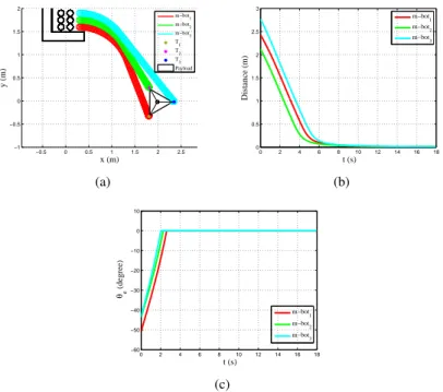
The control law was simulated for a group of three m-bots transporting an object. Fig. 7(a) presents the goal reaching problem with k=22 and σ = 0.1. In order that the m-bots reach the desired positions, the desired speed when reaching the goal is set to zero and then the whole structure will navigate with a speed of 10 cm/s
−0.5 0 0.5 1 1.5 2 2.5 −1 −0.5 0 0.5 1 1.5 2 x (m) y (m) m−bot 1 m−bot 2 m−bot 3 T 1 T 2 T 3 Payload (a) 0 2 4 6 8 10 12 14 16 18 0 0.5 1 1.5 2 2.5 3 t (s) Distance (m) m−bot 1 m−bot 2 m−bot 3 (b) 0 2 4 6 8 10 12 14 16 18 −60 −50 −40 −30 −20 −10 0 10 t (s) θe (degree) m−bot 1 m−bot 2 m−bot 3 (c)
Fig. 7 M-bots target reaching (TR): a) Trajectories of the m-bots reaching the desired positions; b) Position error for TR; c) Angle Error for TR.
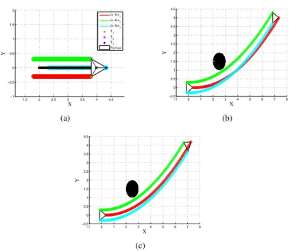
(Fig. 8(a), 8(b) and 8(c)). The payload lays on robot bodies during transport and the group of m-bots is navigating while maintaining constant distances. Fig. 7(b) shows the convergence of the position error e to zero during target reaching phase. Fig. 7(c) presents the angular error for each robot. One can note the convergence to zero of the error which shows the target reaching achievement. Fig. 8(a), 8(b) and 8(c) show respectively the payload transport in a straight line, considering obstacle avoidance while keeping the payload orientation and finally with a new payload orientation. One can note that all m-bots keep a null position errors which means that the forma-tion is properly maintained and that slippage avoidance and task performance are ensured. It is important to notice, that in this paper, we suppose a centralized control of the fleet of robots, thus, the movement of the virtual structure is already defined according to the configuration of the environment. Indeed, the focus of this paper is on the presentation of the virtual structure and the way how each elementary robot keeps the desired position relative to the payload.
4 CONCLUSIONS AND FUTURE WORK
This work takes place within the C3Bots project, that aims to design simple robot entities (m-bots) able to co-manipulate and transport payloads of any shape by
ag-12 B. Hichri, L. Adouane, J-C. Fauroux, Y. Mezouar and I. Doroftei 1.5 2 2.5 3 3.5 4 4.5 −1 −0.5 0 0.5 1 1.5 2 X Y m−bot 1 m−bot 2 m−bot 3 T 1 T 2 T 3 Payload (a) −1 0 1 2 3 4 5 6 7 8 −0.5 0 0.5 1 1.5 2 2.5 3 3.5 4 4.5 X Y (b) −1 0 1 2 3 4 5 6 7 8 −0.5 0 0.5 1 1.5 2 2.5 3 3.5 4 4.5 X Y (c)
Fig. 8 Virtual structure (VS) navigation: a) The p-bot is navigating as a rigid Virtual Structure (VS); b) The p-bot avoids the obstacle and keeps the same orientation; c) The p-bot avoids obstacle and changes the payload orientation.
gregating in a modular way into a poly-robot (p-bot). This work has the ambition to combine two criteria in an original way:
• On one side, the Static Stability Margin (SSM), generally used for legged loco-motion.
• On the other side, Force Closure Grasping (FCG), used for stable multi-finger manipulation.
The m-bots used in this work include in their lower part a wheeled-axle, which is similar to a foot of a multi-leg mobile robot, and in their top part a manipulator act-ing like the fact-inger of a robotic hand. The resultact-ing p-bot ensures the stable payload grasping and transport. An algorithm was developed in order to search the opti-mal positions of n unicycle m-bots that ensure force closure grasping and maximize the static stability margin for the transport of a payload of any shape, defined by its closed curve boundary. Simulation results using a multi-body dynamic software val-idates our proposal and shows the ability of robots to maintain the payload stability during lifting process. A flexible control architecture was used to validate the tar-get reaching problem while maintaining the chosen formation. This navigation was considered in a flat structured environment. Future works will consider the problem of payload manipulation and lifting in all terrain. Unreachable areas on the payload
boundary will also have to be taken into consideration (as for example one side of a square object opposed to a wall).
Acknowledgements The C3Bots project acknowledges the following entities: LABEX IMobS3
Innovative Mobility: Smart and Sustainable Solutions, the French National Centre for Scientific Research (CNRS), Auvergne Regional Council and the European funds of regional development (FEDER).
References
1. A. Benzerrouk, L. Adouane, L. Lequievre, and P. Martinet, ”Navigation of multi-robot for-mation in unstructured environment using dynamical virtual structures,” in 2010 IEEE/RSJ International Conference on Intelligent Robots and Systems (IROS), 2010, pp. 5589-5594. 2. A. J. Ijspeert, A. Martinoli, A. Billard, and L. M. Gambardella, ”Collaboration Through the
Exploitation of Local Interactions in Autonomous Collective Robotics: The Stick Pulling Experiment,” Autonomous Robots, vol. 11, no. 2, pp. 149-171, Sep. 2001.
3. A. Sahbani, S. El-Khoury, and P. Bidaud, ”An overview of 3D object grasp synthesis algo-rithms,” Robotics and Autonomous Systems, vol. 60, no. 3, pp. 326-336, Mar. 2012. 4. A. Yamashita, J. Sasaki, J. Ota, and T. Arai, ”Cooperative Manipulation of Objects by
Mul-tiple Mobile Robots with Tools,” in Proceedings of the 4th Japan-France/2nd Asia-Europe Congress on Mechatronics, 1998, pp. 310-315.
5. B. Hichri, J. C. Fauroux, L. Adouane, Y. Mezouar, and I. Doroftei, ”Design of Collaborative, Cross and Carry Mobile RoBots (C3Bots)” Advanced Materials Research, vol. 837, pp. 588-593, Nov. 2013.
6. B. Hichri, J. C. Fauroux, L. Adouane, I. Doroftei and Y. Mezouar,”Lifting Mechanism for Payload Transport by Collaborative Mobile Robots”, EUCOMES 2014
7. B. H. Wilcox, T. Litwin, J. Biesiadecki, J. Matthews, M. Heverly, J. Morrison, J. Townsend, N. Ahmad, A. Sirota, and B. Cooper, ”Athlete: A cargo handling and manipulation robot for the moon,” J. Field Robotics, vol. 24, no. 5, pp. 421-434, May 2007.
8. C. Grand. et al.:”Stability and Traction Optimization of a Reconfigurable Wheel-Legged Robot,” The International Journal of Robotics Research, vol. 23, no. 10-11, pp. 1041-1058, Oct. 2004.
9. C. Queiroz: ”A Study on Static Gaits for a Four Legged Robot”, International Conference CONTROL’2000, 2000, Cambridge, UK
10. D. Aarno, J. Sommerfeld, D. Kragic, N. Pugeault, S. Kalkan, F. Wrgtter, D. Kraft, and N. Krger, ”Early Reactive Grasping with Second Order 3D Feature Relations,” in Recent Progress in Robotics: Viable Robotic Service to Human, S. Lee, I. H. Suh, and M. S. Kim, Eds. Springer Berlin Heidelberg, 2008, pp. 91-105.
11. D. Ding, Y.-H. Liu, and S. Wang, ”Computing 3-D optimal form-closure grasps,” in IEEE International Conference on Robotics and Automation, 2000. Proceedings. ICRA , 2000, vol. 4, pp. 3573-3578 vol.4.
12. D. E. Orin, R. B. Mcghee, and V. C. Jaswa, ”Interactive compute-control of a six-legged robot vehicle with optimization of stability, terrain adaptibility and energy,” in 1976 IEEE Conference on Decision and Control including the 15th Symposium on Adaptive Processes, 1976, vol. 15, pp. 382-391.
13. D. F. M Dorigo, Swarmanoid: ”a novel concept for the study of heterogeneous robotic swarms”, IEEE Robotics & amp; Automation Magazine, p. in press, 2012.
14. D. Nguyen:”Constructing Stable Grasps in 3D”, Proc. IEEE International Conference on Robotics and Automation, pp. 234-239, 1987.
15. E. G. Papadopoulos and D. A. Rey, ”A new measure of tipover stability margin for mobile manipulators,” in , 1996 IEEE International Conference on Robotics and Automation, 1996. Proceedings, 1996, vol. 4, pp. 3111-3116 vol.4.
14 B. Hichri, L. Adouane, J-C. Fauroux, Y. Mezouar and I. Doroftei 16. F. Kyota, T. Watabe, S. Saito, and M. Nakajima, ”Detection and evaluation of grasping posi-tions for autonomous agents,” in International Conference on Cyberworlds, 2005, 2005, p. 8 pp 460.
17. J. Estremera, J. A. Cobano, and P. Gonzalez de Santos, ”Continuous free-crab gaits for hexa-pod robots on a natural terrain with forbidden zones: An application to humanitarian demi-ning,” Robotics and Autonomous Systems, vol. 58, no. 5, pp. 700-711, May 2010.
18. J. Sasaki, J. Ota, E. Yoshida, D. Kurabayashi, and T. Arai, ”Cooperating grasping of a large object by multiple mobile robots,” in , 1995 IEEE International Conference on Robotics and Automation, 1995. Proceedings, 1995, vol. 1, pp. 1205-1210 vol.1.
19. J. S. Bay, ”Design of the army-ant cooperative lifting robot”, Robotics & amp; Automation Magazine, IEEE, no. 1, pp. 36 - 43, 1995.
20. J.-W. Li, M.-H. Jin, and H. Liu, ”A new algorithm for three-finger force-closure grasp of polygonal objects,” in IEEE International Conference on Robotics and Automation, 2003. Proceedings. ICRA , 2003, vol. 2, pp. 1800-1804 vol.2.
21. L. Adouane, ”Architectures de controle comportementales et reactives pour la cooperation d’un groupe de robots mobiles,” Universit´e de Franche-Comt´e, PhD thesis report 2005. 22. L. Adouane and N. Le Fort-Piat, ”Hybrid behavioral control architecture for the
coopera-tion of minimalist mobile robots,” in 2004 IEEE Internacoopera-tional Conference on Robotics and Automation, 2004. Proceedings. ICRA ’04, 2004, vol. 4, pp. 3735-3740 Vol.4.
23. M. Abou-Samah, ”Optimal configuration selection for a cooperating system of mobile ma-nipulators”, presented at, in the 2002 ASME Design Eng. Tech. Conf, 2002.
24. M. A. Roa and R. Suarez, ”Finding locally optimum force-closure grasps,” Robotics and Computer-Integrated Manufacturing, vol. 25, no. 3, pp. 536-544, Jun. 2009.
25. M. Fischer, P. van der Smagt, and G. Hirzinger, ”Learning techniques in a dataglove based telemanipulation system for the DLR hand,” in 1998 IEEE International Conference on Robotics and Automation, 1998. Proceedings, 1998, vol. 2, pp. 1603-1608 vol.2.
26. M. G. Souma Alhaj Ali, ”Mobile Robotics, Moving Intelligence,” 2006.
27. M. Hueser, T. Baier, and J. Zhang, ”Learning of demonstrated grasping skills by stereoscopic tracking of human head configuration,” in Proceedings 2006 IEEE International Conference on Robotics and Automation, 2006. ICRA 2006, 2006, pp. 2795-2800.
28. R. B. McGhee and A. A. Frank, ”On the stability properties of quadruped creeping gaits,” Mathematical Biosciences, vol. 3, pp. 331-351, Aug. 1968.
29. R. Siegwart and I. R. Nourbakhsh, ”Introduction to Autonomous Mobile Robots”. The MIT Press, 2004.
30. S. Ekvall and D. Kragic, Interactive grasp learning based on humain demonstration, IEEE/RSJ International Conference on Robotics and Automation, New Orleans, USA, 2004
31. S. El-Khoury, A. Sahbani, P. Bidaud.:”3D objects grasps synthesis: a survey”, 13th Worl d Congress in Mechanism and Machine Science, Guanajuato, Mexico, 19-25 June, 2011 32. S. Kernbach, E. Meister, F. Schlachter, K. Jebens, M. Szymanski, J. Liedke, D. Laneri, L.
Winkler, T. Schmickl, R. Thenius, P. Corradi, and L. Ricotti, ”Symbiotic Robot Organisms: REPLICATOR and SYMBRION Projects,” in Proceedings of the 8th Workshop on Perfor-mance Metrics for Intelligent Systems, New York, NY, USA, 2008, pp. 62-69.
33. Simulation results: https://www.dropbox.com/sh/d6plmdqmnizm8j6/AABy52fbl65lhC870ZBdjdQfa 34. T. H. A. Van den Broek. et al.: ”Formation control of unicycle mobile robots: a virtual
struc-ture approach,” in Proceedings of the 48th IEEE Conference on Decision and Control, 2009 held jointly with the 2009 28th Chinese Control Conference. CDC/CCC 2009, 2009, pp. 8328-8333.
35. T. Yoshikawa, ”Multifingered robot hands: Control for grasping and manipulation,” Annual Reviews in Control, vol. 34, no. 2, pp. 199-208, Dec. 2010.
36. Y. H. Liu, ”Qualitative test and force optimization of 3-D frictional form closure grasps using linear programming”, IEEE Transactions on Robotics and Automation, vol. 15, no. 1, 1999 37. Y. Zheng and W.-H. Qian, ”Limiting and minimizing the contact forces in multifingered
grasping,” Mechanism and Machine Theory, vol. 41, no. 10, pp. 1243-1257, Oct. 2006. 38. Z. Wang, X. Ding, A. Rovetta, and A. Giusti, ”Mobility analysis of the typical gait of a radial
symmetrical six-legged robot,” Mechatronics, vol. 21, no. 7, pp. 1133-1146, Oct. 2011.
View publication stats View publication stats