Design and Implementation of a Converter with
Wide Operating Range Using a
Variable-Inverter-Rectifier-Transformer Structure
by
Intae Moon
B.S., Electrical Engineering, University of Illinois Urbana-Champaign
(2016)
Submitted to the Department of Electrical Engineering and Computer
Science
in partial fulfillment of the requirements for the degree of
Master of Science in Electrical Engineering and Computer Science
at the
MASSACHUSETTS INSTITUTE OF TECHNOLOGY
September 2018
Massachusetts Institute of Technology 2018. All rights reserved.
Signature redacted
A u th or ...
...
Department of Electrical Engineering and Computer Science
Signature redacted
August 31,
2018
C e rt ifi e d b y
...
D v d .J P r e u .I
/
David J. Perreault
Professor of Electrical Engineering and Computer Science
r)
Thesis Supervisor
Accepted
by
...
Sinature redacted
(
L6IeJA.
Kolodziejski
Professor of Electrical Engineering and Computer Science
Chair, Department Committee on Graduate Students
MASSACHUSETTS INSTITUTE OF TECHNOLOGY
OCT 10 2018
LIBRARIES
Design and Implementation of a Converter with Wide
Operating Range Using a
Variable-Inverter-Rectifier-Transformer Structure
by
Intae Moon
Submitted to the Department of Electrical Engineering and Computer Science on August 31, 2018, in partial fulfillment of the
requirements for the degree of
Master of Science in Electrical Engineering and Computer Science
Abstract
Power supplies for portable electronics such as cell phones, tablets, and laptops charac-terized by the low-voltage load are supplied by a single-phase grid-tied ac-dc converter. Achieving miniaturization and high efficiency of power supplies in this application is challenging due to the large voltage conversion ratios and the large variations in con-version ratios. The fact that low-output-voltage, large step-down transformers are often constrained by a minimum single-turn secondary also exacerbates loss and size constraints in such applications. To address this, a new hybrid magnetic-electronic
structure is explored - the Variable-Inverter-Rectifier-Transformer (VIRT). This new
approach enables voltage conversion in which the transformer provides fractional and reconfigurable effective turns. This new VIRT approach is developed, and multiple implementation approaches are explored, designed and implemented. This design is further augmented with a rectifier topology which allows for a full utilization of the effective core area in all modes of operation and hence improvement in a core loss. Moreover, a hybrid Litz-PCB construction of VIRT transformer is explored. This approach reduces copper loss and easily satisfies the voltage insulation requirements in such "off-line" applications (2.5 kV in this case [1]) through use of a triple insulated litz wire.
Thesis Supervisor: David J. Perreault
Acknowledgments
First of all, I would like to thank Texas Instruments who has provided me with the opportunity to work on this exciting project through a generous funding.
I would like to thank Professor David Perreault who has been a great advisor and mentor throughout the project. It has been very enriching experience working with him as I have learned a great deal about what it takes to become a good researcher. His encouragement and great ability to explain complicated concepts in an intuitive manner with patience have greatly helped me overcome obstacles and make progress in the project.
I also would like to thank Mike Ranjram, whom I've been lucky to work with for most parts of the project. His knowledge in power electronics and dedication have been a true inspiration. It has been very enjoyable and educational experience working with him thanks to his kindness and willingness to help and share his knowledge.
I would like to thank my friends at MIT for all those cheat days at Chinatown and adventures in New England area, which have always provided me with fun dis-tractions. I also would like to thank all my colleagues at the power electronics group. I truly enjoy spending time at the lab and office interacting with fun and smart group of people.
Finally, I would like to thank my parents, Chang-Hee Moon and Yun-Hee Kim for their love and support even from oceans apart. They have taught me how to be a kind and humble person by example and constantly encouraged me to become the best version of myself.
Contents
1 Introduction 15 2 Variable-Inverter-Rectifier-Transformer (VIRT) 19 2.1 Principle of Operation . . . . 20 2.2 Electrical M odel. . . . . 22 2.3 Experimental Design . . . . 242.3.1 Stacked Half-bridge Inverter . . . . 25
2.3.2 VIRT Transformer Design and Layout . . . . 27
2.4 Experimental Results . . . . 30
3 Design Analysis : VIRT with Bypass Switch 37 3.1 M otivation . . . . 37
3.2 Principle of Operation . . . . 38
3.3 Experimental Design . . . . 42
3.3.1 VIRT Rectifier with Bypass Switch . . . . 43
3.3.2 LLC Resonant Tank Design . . . . 43
3.4 Hybrid VIRT Transformer . . . . 49
3.4.1 Litz Wire Selection . . . . 51
3.4.2 Winding Configuration . . . . 55
3.5 System Loss Analysis . . . . 59
4 Implementation : VIRT with Bypass Switch 63 4.1 Sim ulation . . . . 63
4.2 VIRT Transformer Evaluation . . . . 67
4.3 Experimental Results . . . . 70
4.4 Other Implementations of the VIRT rectifier . . . . 74
4.4.1 Switched-capacitor Step-down Rectifier . . . . 76
4.4.2 VIRT with a 5-legged Core and Bypass Switches . . . . 78
5 Conclusion 81 5.1 Sum m ary . . . . 81
5.2 Future W ork . . . . 82
5.2.1 Bus Capacitor Volume Analysis . . . . 83
A MATLAB scripts 87 B Prototype Converter : Schematics, Layout, and Bill-of-Materials 117 B.1 VIRT prototype version 1 . . . . 117
List of Figures
2-1 The proposed VIRT Structure [2]. A primary winding around the core
center post is not shown for simplicity. . . . . 20
2-2 Induced current flow on the secondary side in each operating mode. . 21
2-3 Magnetic circuit derivation of VIRT model. Solid lines correspond to
real components of currents, while dotted components correspond to
virtual components of currents invoked for modeling purpose [2]. . . . 23
2-4 The electrical model of the proposed VIRT Structure [2]. . . . . 23
2-5 The electrical model of the stacked half-bridge interfaced with VIRT [2]. 25
2-6 Operations of the stacked half-bridge structure. Note that each C,
1
holds -VIN .. . . .
.. ... . . . ...27
2
2-7 Operations of the stacked half-bridge structure in waveforms. . . . . . 27
2-8 Rac of the transformer over
fs,
for the chosen configurations. Note that all theprimary-side layers (P) in each configuration are connected in series and all the secondary-side layers (S) are connected in parallel. The number of turns for each layer is in parentheses. Note that all configurations have the same effective
conver-sion ratios . . . . . 28
2-9 The proposed layout for an optimized current path showing all possible
current paths for VIRT modes. . . . . 30
2-10 A bad layout example for an sub-optimized current path showing all
2-11 Experimental prototype with close-ups of the VIRT layout [3]. The simplified schematic is shown in Fig. 2-5, and the main components are indicated in Table 2.2. Full schematics, bill of materials and layout
files are presented in Appendix B.1. . . . . 32
2-12 Voltage gain curves versus operating frequency for each inverter mode
[3 ]. . . . . 3 3
2-13 Voltage waveforms validating expected symmetric operation of the Al
and B1 rectifiers : HB/HB mode, V, = 120 V, Vo0 t = 9 V, Pout = 36
W ,
f,,
= 558.5 kHz [3]. . . . . 342-14 Power stage efficiency at full load [3]. . . . . 34
3-1 Proposed VIRT structure with the bypass switch and induced current flows
on the secondary side in each operating mode. HB/HB and HB/0 are con-ventional VIRT modes introduced in Chapter 2 and are improved by the
FB/bypass and HB/bypass modes, respectively. . . . . 39
3-2 Electrical models of the proposed VIRT structure in Fig. 3-1. . . . . 40
3-3 Magnetic circuit derivation of the VIRT model. Solid lines correspond to
real components of currents, while dotted components correspond to virtual
components of currents invoked for modeling purpose [2]. . . . . 41
3-4 Schematics of the DC-DC VIRT system with the bypass switch. . . . . 42
3-5 Voltage gain and ZVS curves generated through MATLAB. . . . . 46
3-7 Operations of the stacked half-bridge structure. Note that each Cj"
1
holds V n. . . . . 47
3-8 LitzOpt user interface page [4]. . . . . 51
3-9 Rac vs
f,,
for three different litz wire designs chosen from Table 3.5an d 3.6. . . . . 54
3-10 Possible winding configurations of the hybrid transformer. . . . . 55
3-11 Secondary-side ac resistance Racsec for possible transformer winding
configurations . . . . 56
3-13 Diagrams with scale of non-interleaved and partially-interleaved hybrid
transformers. (The drawings are not to scale.) . . . . 58
3-14 Design curves of the DC-DC VIRT system for an intuitive loss analysis. MATLAB scripts for generating these curves are included in Appendix A . . . ... ... ... ...60
4-1 LTspice simulation schematics. . . . . 64
4-5 Good tuning vs poor tuning of the rectifier switches. . . . . 66
4-9 Diagram and Picture of Hybrid litz-PCB construction of VIRT transformer. The litz wire used for the winding is 48 AWG / 180 strands (5 bundles where each bundle contains 36 strands). . . . . 69
4-10 Schematic and prototype pictures of the DC-DC VIRT system with the bypass sw itch. . . . . 71
4-15 Power stage efficiency comparison and thermal pictures around the VIRT transformer taken during HB/0 and HB/bypass modes : the performance improvements brought by the bypass switches are experimentally verified. . 75 4-17 Switched-capacitor step-down rectifier as a VIRT rectifier . . . . 77
4-18 The VIRT structure with a 5-legged core and bypass switches . . . . 78
5-1 Board picture of the area-optimized DC-DC VIRT system with the by-pass switch and planar windings (secondary-side) of the hybrid trans-form er. . . . . 82
A-1 Voltage gain and ZVS curves generated through MATLAB scripts (VIRTSystemGainZVS.m and VIRTvoltageGainPlotter.m). . . . . 88
B-i VIRT prototype vi: schematic sheet 1. . . . . 119
B-2 VIRT prototype vi: schematic sheet 2. . . . . 120
B-3 VIRT prototype vi: schematic sheet 3. . . . . 121
B-4 VIRT prototype vi: layout layer 1 (115 mm x 70 mm). . . . . 122
B-5 VIRT prototype vi: layout layer 2 (115 mm x 70 mm). . . . . 123
prototype v1 : layout layer 4 (115 mm x 70 mm). . . . . prototype v2 Inverter Board : schematic sheet 1. . . . . B-9 VIRT prototype v2 Inverter Board: layout
B-10 VIRT prototype v2 Inverter Board: layout B-11 VIRT prototype v2 Inverter Board : layout B-12 VIRT prototype v2 Inverter Board: layout B-13 VIRT prototype v2 LLC resonant tank and
sheet 1. ...
B-14 VIRT prototype v2 LLC resonant tank and sheet 2. ...
B-15 VIRT prototype v2 LLC resonant tank and
sheet 3. . . . .
B-16 VIRT prototype v2 Inverter Board: layout
B-17 VIRT prototype v2 Inverter Board: layout
B-18 VIRT prototype v2 Inverter Board : layout B-19 VIRT prototype v2 Inverter Board: layout B-20 VIRT prototype v2 Inverter Board : layout B-21 VIRT prototype v2 Inverter Board : layout B-22 VIRT prototype v2 Inverter Board: layout B-23 VIRT prototype v2 Inverter Board: layout
layer 1 (67 mm x 36 mm). layer 2 (67 mm x 36 mm). layer 3 (67 mm x 36 mm). layer 4 (67 mm x 36 mm). VIRT rectifier : schematic
. . . ..
VIRT rectifier : schematic
...
VIRT rectifier : schematic
layer 1 layer 2 layer 3 layer 4 layer 5 layer 6 layer 7 layer 8 .( . . . . . . .m. (107 mm x 47 mm). (107 mm x 47 mm). (107 mm x 47 mm). (107 mm x 47 mm). (107 mm x 47 mm). (107 mm x 47 mm). (107 mm x 47 mm). (107 mm x 47 mm). B-7 VIRT B-8 VIRT 125 127 128 129 130 131 132 133 134 135 136 137 138 139 140 141 142
List of Tables
2.1 Summary of VIRT operations. Detailed derivations for FB/FB, HB/HB,
and HB/O modes are covered in [2]. Note that "net" magnetizing
in-ductance is calculated assuming a fixed gap across all three core legs. 24
2.2 List of main components and LLC resonank tank design [2] . . . . 26
2.3 Quantification of the current excursions using square resistances. Note
that the current path length is normalized by the estimated trace width. 31
3.1 Summary of VIRT operations. Detailed derivations for FB/FB, HB/HB, and HB/O
modes are covered in [2]. Note that "net" magnetizing inductance is calculated assuming an identical gap on all three core legs. A design with a gap only in the
center post would have different values for magnetizing inductances. . . . . 40
3.2 Minimum and maximum LLC voltage gains (Mg,LLC), effective load
resistances (Re!!), and quality factors (Qe) for all operation modes of
the VIRT with the bypass switch . . . . 44
3.3 LLC resonant tank design . . . . 44
3.4 Reference Design. More details about the design available in Chapter
3 .3 .2 . . . . 5 2
3.5 Buildable design table generated through LitzOpt in the worst current
case ('winding = 1.303 Arms at
fe,
= 713 kHz) . . . . 533.6 Buildable design table generated through LitzOpt in the worst
fre-quency case (Iwinding = 0.768 Arms at
fsw
= 1.3 MHz) . . . . 534.2 Modes of operation for the VIRT with a switched-capacitor step-down
rectifier. . . . . 78
4.3 Modes of operation for the VIRT structure with a 5-legged core. . . . 79
B.1 Bill of materials for the main components in VIRT prototype v1 . . . 126
Chapter 1
Introduction
In the consumer electronic market, there has been a great interest in miniaturizing chargers that power portable electronics such as smartphones, tablets, and laptops. In parallel with this trend, advances in power semiconductors such as Gallium Nitride FETs have opened up opportunities for miniaturization and efficiency of these convert-ers. However, advancement in passive components such as inductors and capacitors have not kept pace with that of power semiconductor technology. Consequently, the performance of many power converters, including size and efficiency, are largely de-termined by passive components, especially magnetic components due to their major
contribution to the power transfer mechanism of the converter [5].
In "off-line" (grid-tied) charger applications, a transformer with a large turns ratio is often implemented to provide the large step-down conversion from the high (and variable) grid voltage to the low-voltage levels needed for the output. This transformer
must meet the safety isolation requirement and - for many designs - widely varying
voltage conversion ratios [6]. This type of large step-down, low-voltage-output design
often leads to the situation where the secondary comprises a (minimum) single turn, and the copper loss of the transformer greatly exceeds the core loss. This imbalance of the loss mechanisms (driven by the inability to further reduce secondary turns) compromises the efficiency of the transformer. The ability to minimize loss is fun-damentally limited since a full single turn is required for a conventional transformer. In other words, if the transformer losses are not balanced and optimized after either
winding reaches a single turn, one either has to accept the losses as they are or find another means to optimize transformer losses such as using a larger transformer core or changing the turns ratio.
Therefore, transformers that can - in some true sense - achieve fractional turns
are extremely valuable in applications requiring low voltage outputs where the ideal secondary would have less than one turn. While previous research has touched upon
"flux-division" approaches towards fractional turns [7], [8], these previous approaches
do not fully help reduce the copper-loss concerns of low-voltage transformer design. In addition, the converters with these large step-down transformers are often required to accommodate wide operating ranges. As a notable example, a Universal Serial
Bus - Power Delivery (USB-PD) wall charger needs to be designed such a way that
it can accommodate the universal ac voltage (85 - 265 Vac) from the grid as an
input and provide a regulated output voltage between 5 Vc and 20 Vc [6]. This design requirement imposes a great challenge to implementing the compact, efficient converter design due to the large step-down ratios and large variations in operating voltages.
This thesis explores the development, design and application of a hybrid electronic-magnetic transformer structure, the Variable-Inverter-Rectifier-Transformer (VIRT), that addresses these challenges [2]. In Chapter 2, the magnetic circuit and electrical model of the proposed structure are developed and the prototype is designed and implemented to verify the model and its benefits in the wide operating condition. In Chapter 3, the VIRT rectifier topology augmented with the "bypass" switch which enables an utilization of the full core area across all VIRT modes of operation is introduced. In addition, a hybrid transformer where its primary-side winding consists of a Litz wire and the fractional secondary turns are built with the PCB traces is introduced and designed in order to further optimize the transformer loss. In Chapter 4, the optimal VIRT DC-DC design with the bypass switch and hybrid transformer carefully chosen in Chapter3 is simulated, implemented, and tested. Its performance with the bypass switch is compared to the conventional VIRT mode of operation. Finally, other rectifier implementation approaches for the VIRT structure
Chapter 2
Variable-Inverter-Rectifier-Transformer
(VIRT)
In order to address the design challenge with a high-turns ratio transformers limited
by a single-turn winding, we have recently proposed a new hybrid electronic and
mag-netic structure named a Variable-Inverter-Rectifier-Transformer (VIRT) that achieves a transformer with a fractional and reconfigurable effective turns ratio [2]. The pro-posed structure is named this way because it realizes the hybridization between an electronic structure, an inverter or rectifier, and a magnetic structure of the trans-former, which provides a variable conversion ratio and effective fractional turns. The effective fractional turn enabled by the proposed structure enables a reduced copper loss and miniaturization by providing a designer with a means to further scale down the absolute number of turns for the transformer, enabling overall loss minimization. In addition, the variable effective conversion ratio enables the proposed structure to better accommodate wide operating voltages without compromising efficiency and overall size of the system.
V OUT
A2
B1
GN D
Al
B2
GND
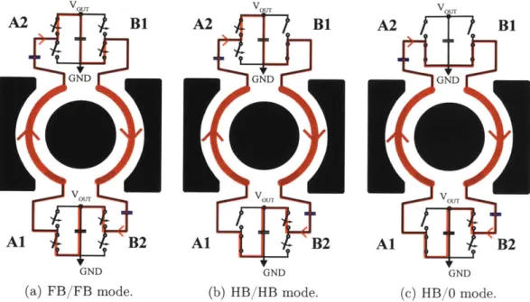
Figure 2-1: The proposed VIRT Structure [2]. A primary winding around the core center post is not shown for simplicity.
2.1
Principle of Operation
Shown in Fig. 2-1 is an example of the proposed VIRT structure. A primary winding around the core center post (not shown) generates flux though the center post of the core. The two full-bridge rectifiers named A and B, respectively, are distributed around the magnetic core and connected through two secondary half-turns around the center post. Rectifier A consists of two half-bridge cells labelled Al and A2, and Rectifier B consists of cells BI and B2. Finally, each cell is connected to the output bus terminals, V, and GND through power and ground planes that are routed outside the magnetic core.
Each rectifier can be operated as a full-bridge (FB), half-bridge (HB), or "zero" mode. When a rectifier is operated in a FB mode, both half-bridge cells (e.g. Al and A2) are active, switching as a full-bridge structure. In a HB mode, only one half-bridge cell is active while the other cell is shorted to the ground. In a zero mode, both cells are shorted to the ground, effectively creating an ac short path for the current to flow for that section of the secondary winding. By combining these two rectifiers, 5 different modes of VIRT can be configured: FB/FB mode, FB/HB mode,
HB/HB mode, FB/0 mode, and finally HB/0 mode [2]. These different modes can be used to support wide output voltage range. For example, in a USB-PD application where the output voltage may be regulated to any of 5 V, 9 V, 15 V, or 20 V, one can select among FB/FB, HB/HB, and HB/0 modes to support the different output voltages while preserving low transformer loss.
V OUT v.OUOU A2 B1 A2 B1 A2
/
B1 GND GND GND vOTvOUT v OUTAl
B2
Al
B2
Al
B2
GND GND GND(a) FB/FB mode. (b) HB/HB mode. (c) HB/0 mode.
Figure 2-2: Induced current flow on the secondary side in each operating mode. An effective turns ratio provided by each mode can be intuitively figured out by looking at the induced current through the secondary winding and the output voltage insertion into the secondary winding through the two rectifiers. For example, in a FB/FB mode (Fig. 2-2a) where both rectifiers A and B are in a FB mode and Al and BI cells are switching in phase, the induced current around the secondary loop flows in a way that the output voltage V., is inserted twice into the loop. Given that the flux through the core is generated by applying an ac voltage with peak V onto
the primary winding with Np turns, it yields - = 2V,, = Vt using Faraday's law
Np 0.5
and equating the generated flux. Note that this voltage conversion ratio is effectively equivalent to that of a Np : 0.5 transformer, where Np is the number of primary turns. Similarly, in HB/HB mode (Fig. 2-2b) the output voltage Vt is inserted once into the loop due to the voltage-halving action of the half bridges. This results
in Vp/Np = Vot, which is equivalent to the voltage conversion ratio of a N : 1 transformer. Finally, in HB/O mode (Fig. 2-2c) one can achieve the effective voltage conversion ratio of a Np : 2 transformer since only the half of V., is inserted into the loop. However, in a HB/zero mode an ac short is effectively created around one leg of the core ideally rejecting the ac flux though that section of the core, which increases the peak flux density of the given core due to the reduced effective core area and hence core loss. This poor utilization of the core area can be resolved by utilizing the bypass switch introduced in Chapter 3.
2.2
Electrical Model
In order to derive the electrical model of the VIRT structure, one has to come up with a magnetic circuit model based on the current flows around the transformer and
induced flux as shown in Fig. 2-3. 'A and iB represent the current flows between the
half-bridge cells in full-bridge rectifiers A and B, respectively. The current components of 1A and 1B inside the core are expected to be equal since two half-turns and rectifiers
A and B shown in Fig. 2-1 are identical and symmetric and effectively form a single
loop around the center post which the primary-side induced flux passes through.
Therefore, the current components of 'A and 'B outside the core, represented as
dotte lines in Fig. 2-3a, are virtual and invoked for the modeling purpose along with
the another virtual current component 'G serving to cancel out virtual components
of 1A and 'B such that the net current flow in this model is equivalent to the flow of
the physical current inside the core as shown in Fig. 2-2a [2].
Fig. 2-3b shows the resulting magnetic circuit with a transference element, L,
associated with the small resistance RSH of the ground plane around the core in a
magnetic circuit [9]. Due to the small resistance associated with the ground plane, it
is safe to assume RSH is close to zero and the resulting magnetic circuit simplifies to
a standard three-winding transformer as shown in Fig. 2-3c [2]. Due to the geometry
of the EQ type core, one can assume RCA = RCB and (DA = IB. Finally, an electrical
iG
(a) Diagram of the VIRT (b) Resulting magnetic circuit
transformer with current model with a transference
flows, element. CA C B -4 ' ++ IA N/, 'B (c) Simplified magnetic
circuit model with RSH t e
0.
Figure 2-3: Magnetic circuit derivation of VIRT model. Solid lines correspond to real components of currents, while dotted components correspond to virtual components of currents invoked for modeling purpose [2].
Al A2 L, N /2:0.5 + LA BOUT N /2:0.5
LB
CBLOCK BI B2Figure 2-4: The electrical model of the proposed VIRT Structure [2].
Fig. 2-3c.
With the derived electrical model in Fig. 2-4, one can compute magnetizing inductance in each mode of VIRT operations. In a symmetric operation such as
Table 2.1: Summary of VIRT operations. Detailed derivations for FB/FB, HB/HB, and HB/O modes are covered in [2]. Note that "net" magnetizing inductance is calculated assuming a fixed gap across all three core legs.
VIRT mode Description Effec Raio Mode Type "Net" Magnetizing
Nu
FB/FB (Fig. 2-2a) All switches active Np : 1/2 Symmetric LM = NP
2Rcc
HB/HB (Fig. 2-2b) A2, B2 active Np: I Symmetric Lm ______________Al, 131 short to GND N:1 SmercL
HB/O (Fig. 2-2c) Al, A2, B2 hort to GND Np: 2 Asymmetric -Lm
"Net" magnetizing inductance means LA + LB in Fig. 2-4.
N2
FB/FB and HB/HB mode, it is straightforward to derive LA = LB = R
2R0c + RC A
assuming RCA = RCB and 4p = 1
(A - (B where (A =FB. Note that RCA = RCB
-2RCC since the cross section of each side leg of the core is twice larger than that of the center post. In an asymmetric operation such as HB/0 mode, an ac-short is effectively created around one leg of the core ideally rejecting the flux through that section of the core as mentioned before. In a case where half-bridge cells Al, B1, and B2 are shorted to the ground, the overall magnetizing inductance is solely decided by
LA given that on-resistances of the bypassed switches and resistance of the ground
N2
plane around the core are negligible. Therefore, LM = LA R0 0 [2]. A
Rcc + RC A
magnetizing inductance in each VIRT mode is listed in Table 3.1.
2.3
Experimental Design
In order to demonstrate the proposed VIRT structure and its benefits in a wide input and output range operation, an experimental prototype, which handles the input
voltage range of 120 - 380 Vc and regulates the output voltage to any of 5 V, 9 V,
and 12 V at 5 A, 4 A, and 3 A, respectively, has been designed and built. These operating points which require widely varying, high conversion ratios are particularly suitable for the VIRT application. Furthermore, a stacked half-bridge inverter which compresses the widely varying input voltage is implemented with a LLC resonant tank and VIRT implemented on the rectifier side as shown in Fig. 2-5.
an effective load resistance (Reff) and voltage gain (Mg) are different for each VIRT operating mode. In addition, one needs to ensure the primary-side ZVS and voltage gain requirements in all operating modes are met in order to design high performance
DC-DC VIRT system. Details on designing a LLC resonant tank with the VIRT
are covered later in Chapter 3.3. The chosen LLC design parameters and list of components for this prototype are shown in Table 2.2.
... Al A2 C Lr 6-0.5 C BLOCK +i I LA V I-V- _-~d V
e
V + _r 6:0.5T~m
B V j !C . .d 0 . LBB1 __-__CBLOCK B1 B2VIRT structure with N = 12
Figure 2-5: The electrical model of the stacked half-bridge interfaced with VIRT [2].
2.3.1
Stacked Half-bridge Inverter
A stacked half-bridge structure uses two different modes to compress the input
volt-age range, through use of the Variable-Frequency Multiplier ("VFX") technique by yielding an ac square waveform at the inverter output with an amplitude that is half (Mode 1) or quarter (Mode 2, "VFX") of the input voltage VIN in the lowline (120
-190 V) or high-line (-190 - 380 V) range, respectively, as shown in Fig. 2-6 and Fig. 2-7 [10]. Due to this input voltage compression, for a range of Va of 120 - 380 V, the
peak voltage range of the square waveform that a LLC resonant tank has to handle is only 47.5 - 95 V. Furthermore, a stacked half-bridge inverter structure makes it easier to achieve the primary side zero voltage switching (ZVS). Disregarding energy
conver-sion effects of larger capacitances such as C, and Cj, it aligns the device capacitors
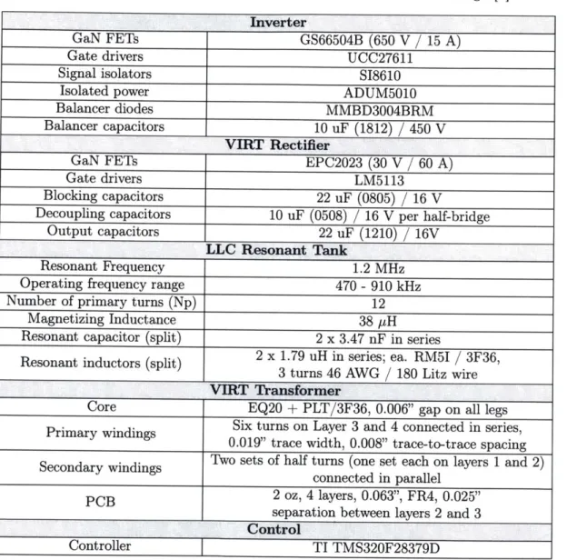
Table 2.2: List of main components and LLC resonank tank design [2J Inverter
GaN FETs GS66504B (650 V / 15 A)
Gate drivers UCC27611
Signal isolators S18610
Isolated power ADUM5010
Balancer diodes MMBD3004BRM
Balancer capacitors 10 uF (1812)
/
450 VVIRT Rectifier
GaN FETs EPC2023 (30 V / 60 A)
Gate drivers LM5113
Blocking capacitors 22 uF (0805) / 16 V
Decoupling capacitors 10 uF (0508) / 16 V per half-bridge
Output capacitors 22 uF (1210) / 16V
LLC Resonant Tank
Resonant Frequency 1.2 MHz
Operating frequency range 470 - 910 kHz
Number of primary turns (Np) 12
Magnetizing Inductance 38 pH
Resonant capacitor (split) 2 x 3.47 nF in series
2 x 1.79 uH in series; ea. RM5I / 3F36,
3 turns 46 AWG / 180 Litz wire
VIRT Transformer
Core EQ20 + PLT/3F36, 0.006" gap on all legs
Six turns on Layer 3 and 4 connected in series,
Primary windings 0.019" trace width, 0.008" trace-to-trace spacing
Two sets of half turns (one set each on layers 1 and 2) connected in parallel
PCB 2 oz, 4 layers, 0.063", FR4, 0.025"
PCB separation between layers 2 and 3
CC.r....TIT..2ntFo2
the device capacitors compared to a conventional half-bridge structure with the same input voltage VIN. More details on achieving the primary side ZVS are covered later in Chapter 3.3. Finally, a balancing circuitry which consists of an array of didoes and capacitors is implemented to ensure input capacitors hold half the DC input voltage.
C in
(a) Voltage halving operation (Mode 1: b- 4D2)-C i VI
_Ti
(b) Voltage quartering operation (Mode 2 : 41 4D2 -+ 13 -+ D4).Figure 2-6: Operations of the stacked half-bridge structure. Note that each C, 1
holds IN.
2
1 L 2 ' 01 L 02
(a) Mode 1: Vi = 120 - 190 V.
Figure 2-7: Operations of the stacked Vh/2
(b) Mode 2: Vi = 190 - 380 V.
half-bridge structure in waveforms.
2.3.2
VIRT Transformer Design and Layout
Planar magnetics have gained increasing popularity owing to miniaturization and ease of fabrication [11], [12]. In order to properly exploit the benefits of the VIRT structure and demonstrate its great promise for miniaturization and loss reduction, a planar transformer where both primary and secondary windings consist of PCB traces has been implemented. Transformer parameters such as a core shape, the number of
V .
primary-side turns (Np), and the number of PCB layers for each winding need to be carefully chosen to ensure high performance operations of VIRT.
The number of the primary-side turns with the single secondary-side turn for a wide operating condition can be computed in Equation (2.1).
N J = Mg,mean kinvVin,mean ~ 12.58, (2.1)
Vout,mean
where Mg,mean, the mean gain of the LLC resonant tank, is 1.38 (Mg,max = 2.53 and
Mg,min = 0.76), kinv, the voltage gain of the stacked half-bridge inverter stage, is ,
Vin,mean 155 V (Vin,max = 190 V and Vn,min = 120 V), and finally Vut,mean = 8.5 V
(Vout,max = 12 V and Vout,min = 5 V). In order to make the planar transformer simple
and symmetric, an even number 12 has been chosen as the number of the primary-side turns Np. Note that in FB/FB mode the VIRT transformer effectively achieved 12
: 0.5 turns ratio whereas a conventional transformer achieves same step-down ratio
with 24 turns on the primary-side winding.
Config. 1 : P(12) -P(12) -S(1) -S(1), conventional Transformer
-- Config. 2: S(1) -S(1) -P(6) -P(6) -P(6) -P(6) -S(1) -S(1), conventional Transformer -- Config. 3 : P(6) -P(6) -S(1) -S(1), VIRT transformer
--- Config. 4: S(1) -S(1) -P(3) -P(3) -P(3) -P(3) -S(1) -S(1), VIRT transformer
4 2-3 - - - --- --- --- --- ---0 I 400 500 600 700 800 900 1000 1100 1200 1300 f SW(kHz)
Figure 2-8: Rae of the transformer over
f.
for the chosen configurations. Note that all theprimary-side layers (P) in each configuration are connected in series and all the secondary-side layers (S) are connected in parallel. The number of turns for each layer is in parentheses. Note that all configurations have the same effective conversion ratios.
In order to quantitatively analyze the improved performance of the VIRT trans-former, it is worthwhile to compare Rac of the VIRT transformer to that of a con-ventional transformer in both interleaved and non-interleaved windings. Since the
secondary-side voltages applied on the transformer ports are the same for the VIRT transformer and conventional transformer with a full-bridge rectifier, the core losses of the both cases are expected to be the same. Therefore, it is the copper loss that makes a difference in terms of transformer performance. M2Spice, a software tool designed to accurately capture skin and proximity effects in multi-layer planar magnetics, is used to generate the circuit netlist for each transformer configuration and compute
Rac [13]. Shown in Fig. 2-8 are Rac of the chosen layer configurations over frequency.
Note that all primary-side layers are connected in series and all secondary-side lay-ers are connected in parallel. As expected, the VIRT transformer shows improved performance in both non-interleaved and interleaved cases. For the prototype, Con-figuration 3, where the planar transformer is built in a non-interleaved fashion with two layers of the primary-side in series comprising the total of 12 turns and another two layers of the secondary-side in parallel comprising a single physical turn, has been chosen due to its performance and cost-effectiveness. An interleaved design such as Configuration 4 would require buried VIAs and substantially increse the cost and complexity of building the PCB with such configuration. In addition, large inner-layer cores need to be used to meet the voltage insulation requirement between the primary and secondary windings (2.5 kV in this application [1]) and increase the volume of a PCB.
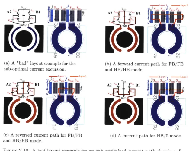
It is important to minimize the current excursions around the core in order to minimize a copper loss contributed by the extended current path and ensure the op-timal operation of VIRT. To this end, a layout of the VIRT transformer and rectifiers needs to be carefully designed while minimizing ac current path as much as possible. Shown in Fig. 2-9 and Fig. 2-10 are the proposed layout of the VIRT rectifier and "bad" layout example for comparison. Note that only top side half-bridge cells along with the VIRT transformer are shown for the sake of simplicity. Nonetheless, the ex-ample current paths shown in the figure cover all possible current paths for different VIRT modes. Note that all switches are placed on the same side of the board since they would have placed substantially far from the transformer due to the voltage in-sulation requirement if placed on the other side of the board where the primary-side
v_ S s A2H A s sH
s ," f ' B1 81
GND
--['IC)
(a) A layout for the optimal current excursion. SLayer I - Layer 2 A2 " "'" B1 A2 A BIL B A20
*fl
C0 G ND(c) A reverse current path for FB/FB and HB/HB mode.
Figure 2-9: The proposed layout for an current paths for VIRT modes.
Layer I - Layer2
VO R AM 'A2L SBIL SBIH>lH
A2 "B1 Room
C
-GND N--
T----OGND
(b) A forward current path for FB/FB
and HB/HB mode.
-Laver I - Layer 2
A2 S H
A2L BIL BIH>
GND (
[.1(1A
(d) A current path for HB/0 mode.
optimized current path showing all possible
winding layers are. Finally, blocking capacitors are placed partially inside the core in order to further reduce the current excursion. As Fig. 2-9 and Fig. 2-10 show, the placement of decoupling capacitors and bus voltage connections (i.e. Vos and GND) can make a huge difference in terms of the length of a current excursion. Table 2.3 approximately quantifies current paths for both cases using the number of resistance squares normalized by the estimated trace width, proving the proposed layout offers more optimal current paths.
2.4
Experimental Results
In order to experimentally verify the electrical model of VIRT derived in Section 2.2 designed with an LLC resonant tank and stacked half-bridge inverter, the prototype
A2 "
fV J -B1
>0SW
ATi RISRf SH 2LB L SBLL
GND
(a) A "bad" layout example for the sub-optimal current excursion.
- Layer I - Layer 2
VO O sH sA B sL , s BIL
A2 BI
GNDN
[.1.
(c) A reversed current path for FB/FB and HB/HB mode.
Figure 2-10: A bad layout example for possible current paths for VIRT modes.
BLayer - Layer 2
V > SJU S 2LU SBI1 SBIL
A2 S_
v
'B1 2GND
EeL';o
(b) A forward current path for FB/FBand HB/HB mode.
_ Layer I - Layer 2
vA rr A BIH SBIL
A2 s cur'" B1
(d) A current path for HB/O mode.
an sub-optimized current path showing all
Table 2.3: Quantification of the current excursions using square resistances. Note that the current path length is normalized by the estimated trace width.
# of resistance # of resistance
Mode squares squares
(Proposed layout) (Bad layout)
Forward FB/FB 1.95 1.3 and HB/HB Reverse FB/FB 1.95 2.9 and HB/HB HB/0 0.77 1.74
has been built as shown in Fig. 2-11 with the main components listed in Table 2.2. Full schematics, a bill of material and pcb layout files are presented in Appendix B.1. As shown in Fig. 2-12, the voltage gain curves versus operating frequency from the experiments are compared to the ones from the circuit simulation and fundamental harmonic approximation (FHA) analysis. The experimental gain curves show a good
B2 hgh4dm
82 Isw.Ids .... Ground pbane
Half4uns
B-Gopftg 0*p6
(a) Top side (b) Top side, VIRT layout
ILw
(c) Bottom side (d) Bottom side, VIRT layout
Figure 2-11: Experimental prototype with close-ups of the VIRT layout [3]. The simplified schematic is shown in Fig. 2-5, and the main components are indicated in Table 2.2. Full schematics, bill of materials and layout files are presented in
Appendix B.1.
resemblance to the ones from the simulation and FHA analysis. MATLAB script for making the gain curves may be found in Appendix A. Toward higher operating frequencies, the matching becomes more accurate as expected since the FHA analysis can better model the LLC gain characteristic in the vicinity of the resonant frequency, 1.2 MHz in this case, which proves validity of the derived electrical model of VIRT and the LLC resonant tank design.
Shown in Fig. 2-13 are the waveforms demonstrating the symmetric operation of
the VIRT. Note that VA, and VB1 are the voltages across the low-side switches of Al
and B1, respectively, as labeled in Fig. 2-5. These two waveforms collected at V/r
= 120 V, Vou = 9 V, Pot = 36 W, and
f
8w = 558.5 kHz show excellent symmetry,which suggests two rectifiers placed on each side of the VIRT transformer see the same secondary-side induced current as depicted in Fig. 2-2. Note that oscillations in the rectifier waveforms are associated with the device capacitors charging and dis-charging when the secondary-side switches are not conducting and the power transfer from the primary-side is effectively ceased during the LLC operation below the reso-nance. In addition to the well-matching voltage gain curves shown in Fig. 2-12, the
5V, 10 -experim -G -5V, 1f - simulate - --
9-5V,
10 - FHA -99V, 2.250 --- 12V, 40 ---500 0.12 r 0.1 >0 0) WS 550 600 650 700 750 800 850 900 950 Frequency [kHz](a) Inverter Mode 1.
5V, 1 fl -experiment -- 5V, 10 - simulated -- E)--5V, 1. -FHA -9-9V, 2.25n ---- 12V, 4n 0.08 -0.06 -0.04 -0.02 -40 450 500 550 600 650 700 750 800 850 900 Frequency [kHz] (b) Inverter Mode 2.
Figure 2-12: Voltage gain curves versus operating frequency for each inverter mode
[3].
great symmetry shown by these two rectifier waveforms further validates the derived electrical model of the VIRT.
Shown in Fig. 2-14 is the efficiency of the prototype converter versus input voltage at full load. Note that FB/FB mode is used for 5 V output, HB/HB mode for 9 V, and
0.12 0.1 0.08 0.06 0.04 0.02 -ent d > 0 cc
f'--viny 10ov/v
V
sv/v
VSV/V o 5V/vN
~
~
~
w 46n 23Gus0VVaim MWa WII MW
MFrequency SSS.5kHz 558 5k 559.5k 558 5k
Figure 2-13: Voltage waveforms validating expected symmetric operation of the Al
and B1 rectifiers : HB/HB mode, V_ = 120 V, Vou = 9 V, Pot = 36 W,
fs=
558.5 kHz [3]. 100 98 96- 94-92 -90 -88 - 86- 84- 82-80' 100 150 200 250 300 350 400 Input Voltage (V)
Figure 2-14: Power stage efficiency at full load [3].
finally HB/0 mode for 12 V. Two different modes of the stacked half-bridge inverter
are used; Inverter Mode 1 effectively halves the input voltage VIN ranging from 120
- 190 V and Inverter Mode 2 effectively quarters the input voltage VIN ranging from
.0 LU -Inverter Mode 1 * ~-~Z~2 -9- 5V -G- 9V -- 12V
-Inverter Mode 2 I I190 - 380 V. The efficiency ranges from 94.4 - 95.7 % in Inverter Mode 1 and 93.4
-95.2 % in Inverter Mode 2, which shows a great potential of the VIRT structure for
wide input and output range applications, especially when combined with techniques such as variable-frequency multiplication (VFX).
Note that the efficiency for each output shows an increasing trend as the input voltage increases. This is because with the fixed voltage gains from the stacked half-bridge inverter and VIRT rectifier for a certain mode of VIRT operation, a higher input voltage for the fixed output voltage and power results in a higher operation frequency in order to meet the required voltage gain through the LLC resonant tank. As the operation frequency increases toward and beyond the resonant frequency, the circulating current through the LLC resonant tank becomes smaller. This results in the improved performance due to the reduced conduction losses of the inverter and rectifier switches as well as reduced copper loss of the transformer given that the primary-side ZVS is achieved over the entire operating frequency. Finally, the reduced efficiency in Inverter Mode 2 compared to Inverter Mode 1 can be attributed to the additional loss from the inverter mode shift since it has been experimentally
verified that 380 V Mode 2 generates the identical square waveform Vj" exciting the
LLC resonant tank as 190 V Mode 1 does [2]. Despite the ZVS operation of the
primary-side inverter, the fact that each device capacitor in Inverter Mode 2 sees
twice the voltage for the same square waveform V, compared to Inverter Mode 1
Chapter 3
Design Analysis: VIRT with Bypass
Switch
3.1
Motivation
The proposed Variable-Inverter-Rectifier-Transformer (VIRT) structure in Chapter
2 has shown high performance across wide operating conditions (Vi = 120 - 380 V
DC, Vet = 5 - 12 V DC, and P0st = 25 - 36 W) owing to its effective fractional
and reconfigurable turns ratio. This allows a designer to further optimize the overall transformer loss and meet the widely varying operating conditions with a compact, efficient converter design. However, the proposed structure has shown a reduced performance in HB/0 mode which generates an upper-end of the output voltage and power ranges (12 V and 36 W in the proposed design from Chapter 2) due to the poor utilization of the effective core area.
In this chapter, we introduced an improved recitifier topology that utilizes a "by-pass switch". This rectifier topology enables much better utilization of the core area and improves the VIRT performance associated with an asymmetric mode such as HB/0 mode. This technique is especially valuable since HB/0 mode is utilized for a high output voltage and power operation which is often the bottleneck for an ac-ceptable temperature raise of the converter. Furthermore, we introduce a hybrid construction of the VIRT transformer in which the primary-side winding is built
with litz wire and the fractional-turn secondary is constructed with printed windings in a PCB. This structure is implemented to improve the copper loss of the VIRT transformer and benefits from the high window utilization of the primary, the use of the printed circuit board for galvanic isolation, and the controlled geometry and low interconnect loss of the fractional-turn secondary winding. Finally, this chap-ter introduces a systematic design and analysis method for a DC-DC VIRT system implemented with a bypass switch rectifier and a hybrid transformer.
3.2
Principle of Operation
Shown in Fig. 3-la is the proposed VIRT structure with a bypass switch implemented with an EQ type core. Fig. 3-2 shows electrical models of the proposed structure for operation with the bypass switch open and closed. Details on deriving the VIRT electrical model are covered in Chapter 2.2. A primary winding around the center post of the core (not shown) generates flux though the center post. The two full-bridge rectifiers named A and B, respectively, are distributed around the magnetic core and connected through two secondary half-turns around the center post. Rectifier A consists of two half-bridge cells labelled Al and A2, and Rectifier B, cells B1 and B2.
Finally, each cell is connected to the output bus terminals, VOUT and GND through
power and ground planes that are routed outside the magnetic core [2].
Each rectifier can be operated as a full-bridge (FB), half-bridge (HB), or "zero" mode. When a rectifier is operated in FB mode, both half-bridge cells (e.g. Al and
A2) are active, switching as a full-bridge. In HB mode, only one half-bridge cell is
active while the other cell is shorted to ground. In zero mode, both cells are shorted to ground (or to the output bus), effectively creating an ac short-circuit path for the induced current around the associated outer core leg; this has the effect of rejecting ac flux through that core leg.
In a USB-PD application where the output voltage may be regulated to any of
5 V, 9 V, 15 V, or 20 V, one can select among the various VIRT modes in Fig.
V OUT vOU
VOUT
A2
BI
A2
B1
A2
B1
VGND
GND GNDs BYP s BYP s BYP
Al
B2
Al
B2
Al
B2
GND GND GND
(a) Proposed structure (b) FB/FB (c) FB/bypass
VOUT )UTV OUT
A2
B1
A2
BI
A2
BI
GND GND GND
SBY, SBYP S BYP
VO OV OUT
Al
B2
Al
B2
Al
B2
GND ND GND
(d) HB/HB (e) HB/bypass (f) HB/0
Figure 3-1: Proposed VIRT structure with the bypass switch and induced current flows on the secondary side in each operating mode. HB/HB and HB/0 are conventional VIRT modes introduced in Chapter 2 and are improved by the FB/bypass and HB/bypass modes, respectively.
including the bypass modes is shown in Table 3.1. Note, for example, that the HB/O and HB/bypass modes offer four times larger voltage gain than the FB/FB mode. Thus, it is sensible to utilize HB/O or HB/bypass to achieve the 20 V operating point,
Al A2 Lr 6:0.5 BLOCK + LA VOUT 6:0.5 0 LB CBCK B1 B2
(a) FB/FB, HB/HB, and HB/O modes
Figure 3-2: Electrical models of the
Al
L, 12:1
+
BLOCK OUT
CBLOCK B2
(b) FB/bypass and HB/bypass modes
proposed VIRT structure in Fig. 3-1.
and FB/FB to achieve the 5 V point.
Table 3.1: Summary of VIRT operations. Detailed derivations for FB/FB, HB/HB, and HB/O modes are covered in [2]. Note that "net" magnetizing inductance is calculated assuming an identical gap on all three core legs. A design with a gap only in the center post would have different values for magnetizing inductances.
VIRT mode VIRTmod Description Desripion Effective Mode Type "Net" Magnetizing
Turns Ratio MdTye Inductance*
Nu
FB/FB (Fig. 3-1b) All switches active Np : 1/2 Symmetric LM =- P 2Rcc HB/HB (Fig. 3-1d) Al, B1 short to GND A2, B2 active Np: 1 N:1 Symmetric SmercL Lm
FB/byp (Fig. 3-1c) Bpass switch on Np: 1 Bypass Lm
H/(Fg3-B2 active Np smerc2 L
HB/O (Fig. 3-1f) Al, A2, B1 short to GND Np: 2 Asymmetric -L
HB/byp (Fig. 3-le) B2 active, Al short to GND Bypass switch on Np: 2 Bypass LM * "Net" magnetizing inductance means LA + LB
magnetic circuit as shown in Fig. 3-3. in Fig. 3-2a and is derived through modeling
While both HB/0 and HB/bypass modes offer the same effective transformer turns ratio (i.e. same voltage gain), HB/bypass mode can achieve lower losses for the same
conversion requirement. In HB/0 mode an ac short is effectively created around
one leg of the core, ideally rejecting the ac flux though that section of the core as illustrated in Fig. 3-3a. This causes the flux through the center post to be routed through only one of the outer core legs as shown in Fig. 3-3c, increasing the peak flux density through that leg and increasing core loss [2]. The proposed VIRT structure with the bypass switch in Fig. 3-la eliminates this issue, enabling the same gain characteristic to be achieved while maintaining full utilization of the core material.
N a
,.ii. Awn
**.M
----
'1,
N4..y(a) Diagram of the VIRT
transformer with current flows for a magnetic circuit modeling in HB/O mode. e-reCA eRCC U $ca ac ME + N4 A A-A
N,0
(d) Diagram transformer w(c) Simplified magnetic circuit for a magnetic model with RSH and RB -+ 0 in FB/FB and
oft ith cir by - +1 +a A Nf, B Y Rsev
(b) Resulting magnetic circuit
model with a transference element
he VIRT A N,,
current flows
cuit modeling
(e)
Simplified magnetic circuit pass modes model with RSH -+0Figure 3-3: Magnetic circuit derivation of the VIRT model. Solid lines correspond to real components of currents, while dotted components correspond
currents invoked for modeling purpose [2].
to virtual components of
Note that SBYP carries bidirectional current and blocks bidirectional voltage and can be implemented by two "back-to-back" MOSFETs. The "bypass" modes enabled by this switch redirect the current path such that it bypasses the entire rectifier structure on one side of the VIRT and configures the un-bypassed rectifier as a FB or HB as shown in Fig. 3-1c and 3-1e, respectively. HB/bypass mode in Fig. 3-le utilizes the entire effective core area of the transformer as opposed to HB/O mode by allowing the flux generated by the primary side current to be routed through both legs of the core as shown in Fig. 3-3e, which in turn avoids unequal flux densities in the outer core legs and hence reduces core loss. Therefore, the bypass switch provides a means to achieve improved system efficiency in the higher output voltage regime while adding little complexity to the system.
3.3
Experimental Design
C ;L 6:0.5 CBLOCK + + T OUT +LA 2 o-T res -VN _ LA 6:0.5 L B B2 I BLOC B2 ...-... ...-....BL...CK..Stacked half-bridge inverter 12:0.5 (FB/FB mode) VIRT with the bypass switch off
Al
C r Lr 12:1
+
BLOCK VOUT
BLC B2
..-...-.... . .. .. B 2... .
12:1 (FB) & 2 (HB) VIRT with the bypass switch on
Figure 3-4: Schematics of the DC-DC VIRT system with the bypass switch.
In order to verify the benefits of the bypass modes, a VIRT system with bypass switch has been designed and built with a LLC resonant tank and stacked half-bridge inverter as shown in Fig. 3-4; complete schematics, bill of materials, and pcb layout files may be found in Appendix B.2. The input voltage is defined by two ranges: 120
- 170 Vdc and 310 - 380 Vdc. These correspond to the peak of ac line for low-line (85
- 120 Vac) operation and high-line (220 -268 Vac) operation, respectively. A stacked
half-bridge structure uses two different modes to compress the input voltage range
by halving (Mode 1) or quartering (Mode 2, "VFX") VIN in the low-voltage range
or high-voltage range, respectively [10]. The VIRT and LLC work interactively to
regulate the output voltage, VOUT, to 5 V (25 W rating), 9 V (36 W rating), 15 V (45
W rating), and 20 V (50 W rating), respectively. These specifications correspond to
those for a USB-PD charger [6]. Due to these wide input and output voltage ranges
needs special design considerations to meet voltage gains and ensure primary-side ZVS across all modes of operation.
3.3.1
VIRT Rectifier with Bypass Switch
As illustrated in Section 3.2, two synchronous full-bridge rectifiers are implemented along with the bi-directional bypass switch. The bypass modes enabled by this switch redirect the current path such that it bypasses the entire rectifier structure on one side of the VIRT and configures the un-bypassed rectifier as a full-bridge or half-bridge. The re-configurable voltage gain from the LLC rectifier input to the dc output voltage achieved by the VIRT rectifier puts a lower stress on the LLC resonant tank. This results in an efficient LLC performance due to the compressed output voltage range that needs to be regulated by the LLC converter.
The DC-DC VIRT system shown in Fig. 3-4 is designed to regulate the output
voltage in ranges between 5 - 20 V. Since HB/bypass mode offers four times larger
voltage gain than FB/FB mode and twice larger voltage gain than FB/bypass mode, it makes sense to utilize HB/bypass mode to achieve 15 V and 20 V, FB/bypass mode to achieve 9 V, and finally FB/FB mode to achieve 5 V. Therefore, the output
voltage range the LLC converter must regulate to is reduced from 5 - 20 V to 3.75
- 5 V owing to the output voltage compression capability of the VIRT rectifier with
bypass switch.
3.3.2
LLC Resonant Tank Design
In order to design a LLC resonant tank in the proposed DC-DC VIRT system, addi-tional voltage gains from the stacked half-bridge inverter and VIRT rectifier need to be taken into account. The voltage gain of the DC-DC VIRT system can be expressed as shown in Equation (3.1).
___ k
![Figure 2-5: The electrical model of the stacked half-bridge interfaced with VIRT [2].](https://thumb-eu.123doks.com/thumbv2/123doknet/14679740.558967/25.917.167.715.314.571/figure-electrical-model-stacked-half-bridge-interfaced-virt.webp)


![Figure 2-11: Experimental prototype with close-ups of the VIRT layout [3]. The simplified schematic is shown in Fig](https://thumb-eu.123doks.com/thumbv2/123doknet/14679740.558967/32.917.250.667.129.427/figure-experimental-prototype-close-virt-layout-simplified-schematic.webp)
![Figure 2-12: Voltage gain curves versus operating frequency for each inverter mode [3].](https://thumb-eu.123doks.com/thumbv2/123doknet/14679740.558967/33.917.231.703.123.814/figure-voltage-gain-curves-versus-operating-frequency-inverter.webp)


