Design and Shape Control of Lightweight Mirrors
for Dynamic Performance and Athermalization
by
Elizabeth Jordan
Submitted to the Department of Aeronautics and Astronautics
in partial fulfillment of the requirements for the degree of
Master of Science in Aeronautics and Astronautics
at the
MASSACHUSETTS INSTITUTE OF TECHNOLOGY
June 2007
@
Massachusetts Institute of Technology 2007. All rights reserved.
Author ...
-.
•
...
.-...
Department~ of Aeronautics and Astronautics
June 8, 2007
//
Certified by...
David W. Miller
Professor
Thesis Supervisor
A
A iAccepted
by...
.
i..
Jadte Peraire
Chairman, Department Committee on Graduate Students
ARCHIVES
MASSACHUSETTS INSTITUTE
OF TECHNOLOGY
Design and Shape Control of Lightweight Mirrors for
Dynamic Performance and Athermalization
by
Elizabeth Jordan
Submitted to the Department of Aeronautics and Astronautics on June 8, 2007, in partial fulfillment of the
requirements for the degree of
Master of Science in Aeronautics and Astronautics
Abstract
The next generation of space telescopes will need to meet increasingly challenging science goals. For these new systems to meet resolution goals, the collecting area of the primary mirror will need to be increased. However, current space telescope designs are reaching their limits in terms of size and mass. Therefore, new systems will need to include technologies such as lightweight mirrors, segmented or sparse apertures and active optical control. Many of these technologies have no flight heritage, so determining what combinations of technologies will create favorable designs requires detailed modeling and analysis. This thesis examines the design of a lightweight mirror for an advanced space telescope for both dynamic performance and shape control.
A parametric model of a rib-stiffened mirror is created in order to quickly analyze many different mirror geometries. This model is used to examine the homogeneous dynamics of the mirror to determine what geometry will maximize the ratio of stiffness to areal density. The mirror model is then used in a full dynamic disturbance-to-performance analysis so that system disturbance-to-performance can be examined as a function of changes in the mirror geometry. Next, a quasi-static shape control algorithm is developed to control the mirror using in the presence of thermal disturbances. The traditional method of mirror shape control relies on feedback from 'a wavefront sensor in the optical path. A wavefront sensor reduces the amount of light available for image formation, which causes problems when viewing very dim objects. Therefore, this control algorithm uses feedback from sensors embedded in the primary mirror. Control algorithms using both strain gages and temperature sensors are developed and compared to determine which sensor type results in better performance. The shape control algorithm with temperature sensors is analyzed using the parametric rib-stiffened mirror model to determine what geometries are best for shape control. The dynamic analysis is combined with the thermal control analysis in order to determine what mirror geometries will be favorable for both of these problems.
Thesis Supervisor: David W. Miller Title: Professor
Acknowledgments
I would like to thank both the Department of Defense and Xinetics Inc. for your support of this work.
I would especially like to thank my advisor, Dave Miller, for all of his guidance throughout my time in the Space Systems Lab.
Also, thank you to Dave Pearson for all of your support and technical advice. Many parts of this work could not have been completed without the efforts of the MOST team: Lucy Cohan, Tom Gray, Deborah Howell, Ryan Lim, Andrzej Stewart, and Scott Uebelhart.
Finally, these two years would not have been the same without all of my friends in the SSL. Thanks for all of the coffee breaks and happy hours. And, of course, thank you to my family for all of your love and support over the years.
Contents
1 Introduction
1.1 Motivation ... 1.2 Previous Work ...
1.2.1 Parametric Modeling . . . 1.2.2 Lightweight Mirror Design 1.2.3 Mirror Shape Control. . 1.3 Thesis Objectives ...
1.4 Thesis Roadmap ...
2 Lightweight Mirror Optimization for Dynamic
2.1 MOST Model Description ...
2.1.1 Parametric Model Generation... 2.1.2 Integrated Model ...
2.1.3 Performance Metrics ... 2.2 Mirror Finite Element Model ...
2.2.1 Mirror Structure ...
2.2.2 Mirror Mesh Auto-Generation ... 2.2.3 Piezoelectric Actuator Model ... 2.3 Stiffness Optimization ...
2.3.1 Homogeneous Dynamic Analysis ... 2.3.2 Dynamic Performance Analysis... 2.4 Conclusions from Dynamics Model
7
3 Mirror Shape Control with Embedded Sensors 55
3.1 Thermal Disturbance Models ... 56
3.2 Simple One-Dimensional Beam . . . . 58
3.2.1 Beam with Bulk Temperature Change . . . . 59
3.2.2 Beam with Through-Thickness Temperature Gradient . . . . . 60
3.2.3 Beam with Linear Temperature Gradient . . . . 62
3.2.4 Sensor Locations ... 62
3.3 Plate Model for Deformable Mirror . . . . 63
3.3.1 Finite Element Model . . . . 63
3.3.2 Sensor M odels . . . . 65
3.4 Sensor Sensitivity Issues ... 66
3.5 Conclusions . . . 69
4 Static Shape Control Algorithms for WFE Minimization 71 4.1 Traditional Shape Control ... 72
4.2 Control Using Strain Gage Sensors ... 75
4.2.1 Full Feedback Problem . . . . 76
4.2.2 Output Feedback Problem - Numerical Optimization . . . . . 77
4.2.3 Strain Gage Sensor Control on Flat Plate Mirror . . . . 78
4.3 Control Using Temperature Sensors . . . .... .. 80
4.3.1 Output Feedback Problem .. . . . . . . . . ... . 82
4.3.2 Temperature Sensor Control on Flat Plate Mirror . . . . 84
4.4 Conclusions . . . 86
5 WFE Minimization on Simple Plate Model 87 5.1 Strain Gage Control Results ... . . . . . . . . . . ..... 87
5.1.1 Various Disturbance Types ... . . . . . . . . . ..... 88
5.1.2 Parameter Variability ... . . . . . . . . . ..... 90
5.2 Results with Temperature Sensors .... . . . . . . . . ..... 92
5.2.1 Various Disturbance Types .... . . . . . . . . ..... 92
5.2.3 Parameter Variability . ... 97
5.3 Conclusions from Simple Model . ... 99
6 WFE Minimization on a Rib-Stiffened Mirror 103 6.1 WFE Minimization Results ... ... 104
6.2 Parameter Variations ... ... 107
6.2.1 Areal Density Variation ... ... 107
6.2.2 Rib Aspect Ratio Variation .... . . . . . . . . . . ..... 111
6.3 Rib-Stiffened Mirror Control Conclusions . . . . . . . . . . . 113
7 Conclusions 115 7.1 Thesis Summary .. ... 115
7.2 Contributions .. ... 118
List of Figures
1-1 Future Space Telescope Missions: JWST and TPF (courtesy of NASA) 18
1-2 Conceptual and Preliminary Design Phases . . . . 19
2-1 Parametric Modeling Process ... 30
2-2 Modules for Creation of Finite Element Model . . . . 31
2-3 Sample Architectures for Structural Model . . . . 32
2-4 MOST Modeling Process ... 33
2-5 Zernike Shapes ... 35
2-6 Segmented and Monolithic Mirror Models . . . . 38
2-7 Back View of Rib-Stiffened Monolithic Mirror . . . . 38
2-8 Mirror Mesh Generation Method . . . . 40
2-9 Variable Mesh Density for a One Meter Diameter Hexagonal Segment 41 2-10 Piezoelectric Actuator Embedded in Rib . . . . 43
2-11 Fundamental Frequency vs. Mirror Areal Density . . . . 46
2-12 Fundamental Frequency vs. Number of Ribs . . . . 47
2-13 Fundamental Frequency vs. Rib Cross Section Aspect Ratio . . . . . 48
2-14 Fundamental Frequency vs. Mass Proportion in Facesheet . . . . 49
2-15 Tradespace Results Showing Variation in Mirror Type and Areal Density 51 2-16 Tradespace Results Showing Variation in Rib Aspect Ratio . . . . 52
3-1 Across Surface Temperature Distributions Used to Test Control . . . 57
3-2 Simple Beam Model ... ... ... 58
3-3 Beam Model with Bulk Temperature Change . . . . 59
3-5 Simple Beam with Through Thickness Thermal Gradient . . . . 61
3-6 Simple Beam with Linear Temperature Gradient . . . . 62
3-7 Schematic of Actuator Connected to Flat Mirror Model . . . . 64
3-8 Simple Mirror Model with 30, 42 and 72 Actuators (red) . . . . 64
3-9 Locations of Strain Gages (Back Surface Only Shown) . . . . 66
4-1 System Diagram for Traditional Active Optical Control . . . . 72
4-2 Correction of Distorted Mirror by Adding Actuator Influence Functions Scaled by Input Values ... 73
4-3 Control Results for Bulk Temp Change using Strain Gages . . . . 79
4-4 30 Actuator Mirror with Strain Gages: Uncorrected and Corrected Surface with 1lC Bulk Temperature Change . . . . 79
4-5 Layout of Temperature Sensors on Flat Plate Mirror . . . . 83
4-6 Control Results for Bulk Temp Change using Temperature Sensors. . 85 4-7 30 Actuator Mirror with Temperature Sensors: Uncorrected and Cor-rected Surface with 1lC Bulk Temperature Change . . . . 85
4-8 Comparison of Strain Gages and Temp Sensors for Bulk Change . . . 86
5-1 WFE Correction Using Strain Gage Sensors . . . . 89
5-2 Effect of Variability in Actuator CTE, Control using Strain Gages on 12-Actuator Mirror with 1lC Bulk Temperature Change . . . . 91
5-3 Distorted and Corrected Mirror Shape for Linear Temperature Gradient 93 5-4 WFE Correction Using Temperature Sensors . . . . 93
5-5 WFE and Correction Factor for Exponential and Conical Gradients . 94 5-6 Estimation of Exponential Temperature Distribution . . . . 95
5-7 Number of Basis Functions versus Performance of Temperature Sensor Control ... . ... ... ... .. 96
5-8 Controller Performance with Improved Temperature Estimation . . . 97
5-9 Effect of Variability in Actuator CTE, Control using Temp Sensors 98 5-10 Comparison of Sensors for Linear Temperature Gradient . . . . 99
5-12 Comparison of Sensors for Conical Temperature Gradient . . . ... .. 6-1 Rib-Stiffened Hex Segment with Embedded Actuators (Shown in Red) 105 6-2 Initial and Final Results of Temperature-Sensor Based Wavefront
Con-trol on Rib-Stiffened Mirror ... 106
6-3 Initial WFE for Rib-Stiffened Mirror, Variation in Areal Density . . . 108
6-4 Influence Function of Actuator # 1 with Changing Areal Density . . 108 6-5 Final WFE and Correction Factor for Rib-Stiffened Mirror, Variation
in Areal Density ... 109 6-6 Initial Surface Displacements . . . 110
6-7 Controlled Surface Displacements with Bulk Temperature Change . . 110
6-8 Controlled Surface Displacements with Exponential Temperature Change 111 6-9 Initial WFE for Rib-Stiffened Mirror, Variation in Rib Aspect Ratio . 112 6-10 Final WFE for Rib-Stiffened Mirror, Variation in Rib Aspect Ratio . 112
6-11 WFE Correction Factor for Rib-Stiffened Mirror, Variation in Rib As-pect R atio . . . 113
List of Tables
2.1 Silicon Carbide Material Properties . . . . 39
2.2 First 20 Frequencies for One Meter Hexagonal Segment with Varying M esh . . . 42
2.3 Mirror Parameters for Geometry Variations . . . . 45
2.4 Parameters Varied in Tradespace Analysis . . . . 50
2.5 Designs Along Pareto-Front ... 51
3.1 Flat Plate Mirror Model Parameters . . . . 65
Chapter 1
Introduction
The science goals of future telescope missions are becoming more and more ambitious. The James Webb Space Telescope (JWST), shown in Figure 1-1(a), will look back to the origins of the universe to study the formation of the first stars. The Terrestrial Planet Finder, shown in Figure 1-1(b), will search for Earth-like planets orbiting nearby stars. To achieve these science goals, telescopes will need better resolution, which will require new technologies and major design changes. The NASA advanced telescope and observatory roadmap points to some of the new architectures and key technologies which will be necessary to meet the science goals [10]. These technologies include lightweight, segmented or sparse apertures and active optical control.
In order to see these distant stars and Earth-like planets, the collecting area of the primary mirror must be increased [5]. However, as the size of the primary mirror is increased, the size of the launch fairing becomes a constraint. Both segmented and sparse apertures are potential technology options for increasing the mirror diameter. The James Webb Space Telescope, will have a primary mirror with a diameter of 6.5 meters, six times the collecting area of the Hubble Space Telescope [27]. Therefore, the JWST primary mirror is formed from 18 separate segments. This type of segmented system must then be deployed on orbit and will require active controls to ensure that each segment is aligned correctly. Missions such as the Terrestrial Planet Finder (TPF), will use a formation flown interferometer to work as a giant virtual telescope.
(b) TPF Formation Flying Interferometer
Figure 1-1: Future Space Telescope Missions: JWST and TPF (courtesy of NASA)
mirrors. The primary mirror is usually the largest and heaviest component of the telescope, so reducing its mass will have a significant impact on the entire system. By using advanced materials and design techniques, the areal density of the primary mirror on JWST will be more than nine times smaller than the areal density of the Hubble primary mirror. The increased diameter and reduced mass of these new mirrors cause them to be more flexible than traditional mirrors. As a result, pre-launch validation becomes difficult for these large, flexible mirrors. It is impossible to completely replicate a space environment on Earth. The gravity field on Earth has a major effect on the flexible structures being designed. In addition, the next space telescopes will be approaching size limitations of environmental testing chambers. As system validation prior to launch becomes more difficult, the ability to correct defects on-orbit becomes more important.
Active control of the primary can be used on-orbit to correct for defects in the mirror. A manned servicing mission was used to correct the spherical aberration in the Hubble Space Telescope. It is unlikely that servicing missions will be possible for future space telescopes, making the ability to remotely perform corrections on-orbit more important. In addition, deployable mirrors, such as those being designed for JWST, will require initial alignment after launch and will use active control to maintain position. The primary mirror of a space telescope could have errors due to manufacturing, launch, deployment, spacecraft dynamics and changes in the thermal environment. Actuators embedded in the primary mirror can be used to correct the
mirror shape on-orbit.
This thesis will study the design of a lightweight primary mirror with embedded active controls. A parametric finite element model of the lightweight mirror has been created so that various geometric parameters can be changed easily. Using this model, the dynamic performance of the mirror will be studied as the geometric parameters of the mirror are changed. Following this, active controls will be applied in order to control the mirror for thermal disturbances using only sensors and actuators on the primary mirror.
1.1
Motivation
In order to meet the tightened science requirements, future space telescopes will utilize many advanced technologies. Design possibilities now range from the traditional very stiff telescope design to extremely lightweight, highly actuated systems. Determining the best combinations of these new technologies will be a challenge. In the traditional design process, as shown in Figure 1-2, a point design is chosen during the conceptual design phase. This decision is often based on expert knowledge and simple models based on previous missions. Detailed models are usually not created and analyzed until the preliminary design phase. Discovering that a design cannot meet mission requirements during the design phase can lead to costly redesigns, or even a return to the conceptual design phase.
Conceptual Design Phase Preliminary Design Phase
sign Expert FE Model
pace Decision Generated
Next
Design Phase
"No
Figure 1-2: Conceptual and Preliminary Design Phases
The next generation of space telescopes will be radically different from previous designs. Many of the new technologies which will be utilized have no flight heritage,
and so choosing a point design based on expert knowledge can be very difficult. Even if a design is chosen which meets the requirements, there is no guarantee that it is an optimal design. By modeling many architectures early in the design process, favorable families of designs can be identified. In order to explore the large space of potential architectures during the conceptual design phase, it is necessary to quickly build and analyze many models. A parametric model can be used to build and analyze models of systems which include different technologies. This thesis describes the Modular Optical Space Telescope (MOST) tool which is used to create a structural model of a space telescope based on parametric inputs. Analysis is then performed on the structural models so that many different architectures can be compared. The modularity of the parametric model allows new technologies to be included if they are interesting to the user. This parametric model will be used to evaluate the effects of changing primary mirror geometries. This approach is meant to augment rather than replace the role of expert opinion.
The primary mirror design is a major area of technology development for space telescopes. Major advances have been made recently in lightweighting mirrors using both new materials and different designs [17],[20]. There are many potential design options for creating a lightweight mirror. By using a parametric model, it is possible to determine what the optimal geometry of the mirror should be to maximize the stiffness to mass ratio of a primary mirror. The parametric model can also be used to determine how these changes in geometry will affect the overall performance of the system.
There are many potential sources of errors for the primary mirror, including optical manufacturing errors, deployment errors, defects due to launch, spacecraft induced vibrations and thermal deformations. In this thesis, control for quasi-static thermal disturbances will be discussed. These thermal disturbances could be caused by heat radiating from the Earth, or from errors in the heaters used to control the thermal environment. This mirror is designed with embedded actuators in order to directly correct for errors.
the mirror shape [15]. Most wavefront sensors divide the available light between the imaging detection and the wavefront measurement system using a beam splitter. In order to operate, a wavefront sensor must have sufficient light to overcome background noise, and still have enough light left over to form an image. Many scientifically interesting stars are not bright, and cannot be seen once the light is split. If the wavefront error could be measured by using sensors embedded in the primary mirror, all of the available light could be used for the image. In addition, embedded sensors remove the potential for errors to be introduced between the mirror and the sensor.
1.2
Previous Work
An overview of the literature shows that many aspects of space telescope design have been the focus of research in the past decade. Parametric modeling of structures has been used in a number of fields, including the design of telescopes, in order to improve the design process. There have also been many advances in the design of subsystems for space telescopes. Due to the technology advances which will be necessary for future missions such as JWST, the design of lightweight mirrors has been a focus. As lightweight mirrors are designed, the need for active shape control of these mirrors has become increasingly important.
1.2.1
Parametric Modeling
Parametric modeling has been used in a number of fields to improve the design of structures. In the area of automotive design, Botkin [7] uses an MSC Nastran opti-mization routine (SOL 200) to study different realizations of the front structure of an automobile. The goal of this optimization is to reduce the weight of the structure. Feynes [11] develops a high level model of an entire automobile, and uses a hierarchi-cal parametric CAD model to optimize the vehicle structure. This model also allows for the easy addition of new features.
Parametric modeling has also been used in the field of aircraft design. Puorger [24] has developed a code for the conceptual design of aircraft configurations. This code,
MAGIC (Multidisciplinary Aircraft desiGn of Innovative Configurations), includes structural analysis using FEA, buckling analysis, an aerodynamics model and an aeroelasticity model. Smith [28] automatically generates a model of an aircraft based on parametric inputs describing the geometry. This model is then analyzed using CFD. Baker [4] discusses the importance of parametric modeling early in the design cycle of aerospace vehicles. The parametric models are used to improve the weight and performance estimation and identify major problems before the detailed design phase is reached.
Recently, integrated models have been developed for both ground-based and space telescopes. Angeli et al [1], [2] created an integrated model for a ground-based tele-scope. This model includes an integrated structures-optics-controls model, a para-metric cost estimation model and a science merit function. Miller, de Weck and Mosier [23] present the DOCS (Disturbance-Optics-Controls-Structures) framework for integrated modeling, simulation and analysis of optical telescopes, either ground-based or space. This framework is shown to be an efficient method for evaluating various missions. Uebelhart [32] [33] has expanded on this early DOCS framework to create a fully parameterized model for space telescopes. This work also includes an uncertainty model which can be used to identify critical parameters.
1.2.2
Lightweight Mirror Design
An overview of the literature shows that the design of lightweight mirrors is a major focus of research. Large reductions in the areal density of mirrors are required for the larger apertures which will be used in future space telescopes. Baiocchi and Burge [3] have been working at the University of Arizona to optimize the design of lightweight, active mirrors subject to thermal disturbances. They developed a relationship between key design parameters for a lightweight mirror (such as facesheet thickness, number of support points and number of actuators) in order to determine the best geometry for surface quality given a target mass. There has also been research into new material options for lightweight mirrors. Matson and Mollenhauer [22] state that monolithic glass mirrors are reaching their limits in terms of areal
density. They discuss some of the advanced materials which can be used to improve space telescope mirrors, including composite materials, foams and microsphere arrays. These materials will require new manufacturing and polishing techniques to reach the required surface quality.
Some lightweight mirror designs are currently being built and tested in order to demonstrate enabling technologies for the JWST. The Subscale Beryllium Mirror Demonstrator(SBMD) is a 0.532-meter lightweight mirror developed to show that surface quality and areal density goals for JWST could be met using a beryllium mir-ror [25]. It was tested at cryogenic temperatures so that the changes in surface quality could be accounted for as it undergoes cooling. A mirror areal density of under 10
kg/rn2 was achieved for this mirror, not including the actuators or support structure. The Advanced Mirror Systems Demonstrator (AMSD) program extended the work of the SBMD by testing a 1.4-meter hexagon similar to the segments which will be used for the JWST mirror [20]. This mirror will also include cryogenic actuators and a lightweighted support structure.
1.2.3
Mirror Shape Control
Deformable mirrors were first used in adaptive optics systems for ground-based tele-scopes. The capability of ground based telescopes is limited by the atmospheric turbulence which causes stars to twinkle [31]. The performance of these telescopes can be improved by the addition of a deformable tertiary mirror which corrects the errors in the wavefront. A traditional adaptive optics system includes a deformable mirror, a wavefront sensor and a control system. Many different designs exist for the deformable mirror. Freeman and Pearson [13] provide a review of several options for the deformable mirror design for different applications. Segmented mirrors, with piston, tip and tilt control of each segment, are one way of creating an active mirror. It is also possible to design a continuous surface mirror with either surface-normal or surface-parallel actuation. Surface-normal actuators must be mounted to a massive backstructure in order to function, making the deformable mirror too heavy for a space application. Therefore, the shape control work in this thesis utilizes
surface-parallel actuators.
Although ground-based telescopes utilize adaptive optics systems to correct for turbulence in the atmosphere, the current large telescopes being designed are also subject to low spatial-frequency disturbances such as gravity sag, thermal changes and wind-buffeting. To correct for these disturbances, a separate active optics system can be used. Angeli [1] describes a linear optical model developed for the 30-meter class of ground based telescopes. This model, which describes optical path differences in terms of primary and secondary mirror displacements, is a convenient way to design
and analyze active control systems.
Space telescopes are able to perform significantly better than ground-based tele-scopes because they are not limited by atmospheric effects or gravity. However, there are still errors in the primary mirror due to fabrication errors, launch and deploy-ment dynamics, thermal changes and on-orbit spacecraft dynamics. In order to reach diffraction-limited performance, on-orbit shape control of the primary mirror has be-come an important part of space telescope design. Robertson [26] initially developed the active optics concept for space telescopes. He describes the fundamental concept of an active optics system for a space telescope. A thin, deformable mirror was then developed in order to analyze and experimentally test the active optics concept.
Many different studies have been performed to show that the shape of a primary mirror can be controlled in order to improve the imaging capabilities of a space telescope system. In general, a control algorithm is developed based on the influence function of each actuator and the surface correction in the mirror is measured for some form of disturbance. Kapania et al [19] showed that a thin hexagonal segment could be controlled for thermal deformations using either force actuators or piezoelectric strips bonded to the back surface of the mirror. The mirror showed smaller deformations due to the thermal disturbances when it was mounted on force actuators. However, the force actuated system was much heavier than the system actuated by piezoelectrics and is probably not useful for a space application.
Furber et al [14] have worked on the problem of shape control for a one meter deformable mirror. They created a finite element model of a deformable mirror using
Nastran. This model was then used to determine the influence of each actuator in the system. The model developed was then used to simulate the performance of an active control system for various aberrations. The performance of the control algorithm is then analyzed as a function of the number of actuators, the actuator influence functions and the disturbance. Doyle et al [9] present an integrated model which is used to study the active control of a primary mirror. Design trades are performed
by coupling the structural and optical design tools. To achieve this, a commercial code, SigFit is used. This code combines the disturbance and structures with a CODE V optics model in order to determine the best surface correction for a system of apertures.
1.3
Thesis Objectives
This thesis aims to address some issues which remain open in the area of lightweight mirror design for space telescope applications. Parametric modeling techniques will be applied to the design of a rib-stiffened mirror in order to determine favorable geometries for both dynamic performance and control of thermal effects. A particular goal of this model will be to use the desired mirror areal density as an input to the parametric model. This will allow mirrors of equal mass to be compared.
While active control of primary mirrors has been studied for many years, previous control systems have used wavefront sensors located elsewhere in the optical path to measure errors in the mirror. As mentioned earlier, these wavefront sensors usually split the light. In addition other errors could be introduced between the mirror and sensor since they are not collocated. To address this issue, this this thesis will present an algorithm for shape control using only sensors embedded in the mirror.
1.4
Thesis Roadmap
This thesis will discuss the design of a lightweight mirror for both dynamic perfor-mance and athermalization. Chapter 2 describes the development of a parametric
model for a lightweight mirror. This mirror is part of a larger integrated model which includes structures, controls and disturbances. The parametric mirror model is used to study the homogeneous dynamics of the mirror as the geometric properties of the mirror change. Following this, a disturbance to performance analysis of the entire space telescope is performed to determine the effect of the mirror geometry on the telescope performance.
Chapters 3 and 4 then describe the development of control algorithms which can be used to minimize the effects of thermal disturbances on a lightweight mirror using only embedded sensors and actuators. In Chapter 5 these algorithms are analyzed on a circular flat plate with surface-parallel actuators, which is representative of a lightweight mirror. The shape control is analyzed with a varying number of actuators and for a number of potential thermal disturbances. In Chapter 6, the shape control algorithm presented in Chapter 4 is used to control the full rib-stiffened mirror which was presented in Chapter 2. Again, the results of this control are analyzed for differ-ent disturbances. The parametric mirror model is then used to alter the geometric properties of the mirror in order to determine favorable geometries for shape control.
Chapter 2
Lightweight Mirror Optimization
for Dynamic Performance
Advanced space telescopes concepts include increasingly tight requirements on optical performance. In order to create high resolution systems, large apertures are necessary. However, current designs are reaching their limits in terms of mirror diameter and mass. Primary mirror diameter is constrained by the size of current launch fairings. The overall system mass is a major driver of launch costs. If these new telescope designs are to succeed, advanced technologies, such as deployable optics and low areal density mirrors, must be incorporated.
Recently, many new technologies have been developed which can be used to im-prove the design of the primary optics. In particular, segmented mirrors, lightweight-ing and active controls can be used to meet performance requirements while minimiz-ing mass. It is necessary to use segmented mirror systems to achieve large diameters; this way mirrors can be folded into a launch configuration and then deployed on orbit. As the primary mirror diameter increases, the mass of the system will become large. Lightweighting techniques have been developed in order to reduce this mass; how-ever, this can cause the mirror to become flexible. Active controls are then added to the mirror so that the optical performance requirements are met. Because these are new technologies, understanding the appropriate combinations of these technologies requires detailed modeling and analysis.
The Modular Optical Space Telescope (MOST) project has been working to de-velop a parametric model of a space telescope. This includes structural model gen-eration, controls models and a dynamic disturbance to performance analysis. Using this tool, features of the telescope can be easily changed in order to determine the effects of particular parameters on performance metrics. In particular, different mir-ror geometries can be analyzed to find those that provide the highest stiffness for a given areal density. In this chapter an overview of the MOST model will be provided for background. Then, the structural modeling and auto-meshing of the lightweight mirror will be discussed in detail. Finally, the dynamic performance of the lightweight mirror, both attached to the complete telescope model and separated, is described.
2.1
MOST Model Description
The traditional design process for a complex system, such as a space telescope, in-volves the consideration of many design options in the conceptual design phase and the selection of a single point design for the preliminary design. Traditionally, detailed structural models are not created and analyzed until the preliminary design phase. However, if the design does not meet requirements once the analysis is complete, a costly redesign must be performed. Even if requirements are met, there will be no guarantee that the design chosen is optimal.
As new technologies are added to designs, it becomes difficult to make major decisions during the conceptual design phase, because the systems have no operational heritage. For these types of systems, it would be beneficial to evaluate more design options earlier in the design process. A parametric modeling approach applied early in conceptual design allows competing designs to be modeled and compared to one another. Such an approach allows for a large number of different architectures to be evaluated quickly and with a reasonable degree of fidelity. The designer can identify families of architectures which are likely to fulfill the system requirements and to have favorable attributes such as low mass and cost [32].
of a large space telescope which utilizes advanced technologies. Given a set of input parameters, MATLAB is used to automatically create a structural finite element model. A normal modes analysis is then performed on this structural model using the Nastran finite element solver. An integrated state space model is created and analyzed using the DOCS (Disturbance, Optics, Controls, and Structures) integrated modeling toolbox [6]. Each architecture created can be evaluated using different analysis tools such as a dynamic disturbance analysis.
2.1.1
Parametric Model Generation
The goal of completely parameterizing a model is to allow the user to control both major and minor design choices. However, this makes developing the model signifi-cantly more challenging as there can be nearly limitless options for the final system architecture. The model must allow for major changes to the system architecture such as the primary mirror or secondary support tower type, in addition to allowing for changes to the dimensions of structural components or to material properties. Therefore, a completely parameterized model must include the ability to change both the values of numerical inputs and the basic geometry of the spacecraft.
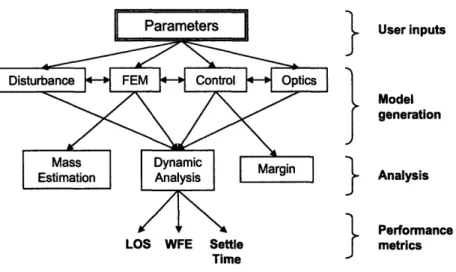
To keep the information flow within the model clear, all inputs to the model are maintained in a separate parameters module. This module contains all design variables and material constants so that any user can quickly find and change variables in order to evaluate a new design configuration. In this way, changes can be made to the model by a user without full knowledge of each low level function. The parametric inputs will then flow from the top-level parameters module down to the lower level component creation modules as required. The input parameters are used to create the control system, finite element, disturbance, and optics models within separate modules. For such a complex and variable model to be created successfully, it is necessary to clearly define the relationships between individual model components. Figure 2-1 shows how the input parameters are passed through the modules. The parametric inputs are used to auto-generate a finite element model (FEM) of the spacecraft structure, as well as to create the disturbance and controller models which
User inputs
SModel
generation
}
Analysis
S Performance
LOS WFE Settle metrics
Time
Figure 2-1: Parametric Modeling Process are then added to the structural model.
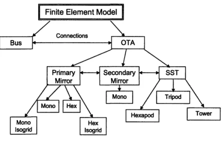
In order to create the structural model, it is necessary to assume a basic architec-ture for the telescope. The spacecraft is designed to have a bus for general spacecraft operations such as communications and pointing. There is a separate optical telescope assembly (OTA) for observations. The bus is a tetrahedral frame which contains the reaction wheel assembly and other instruments. These non-structural components are represented using point masses; the masses of these components are determined using curve-fits based on historical data [34]. The OTA includes a primary mirror (PM), secondary mirror (SM), fast steering mirror (FSM), optics bench and secondary sup-port tower (SST). In addition to each individual structural component, it is necessary to create connections between these model parts. Since the form of the structural components can change according to the input parameters, it is necessary to keep track of the correct attachment points in the module outputs. These connections are then created within separate modules. As shown in Figure 2-2, separate MATLAB modules exist to create the various design options for each of the structural com-ponents. An important feature of this type of model is that it can be extended to include new components by adding more modules.
Figure 2-2: Modules for Creation of Finite Element Model
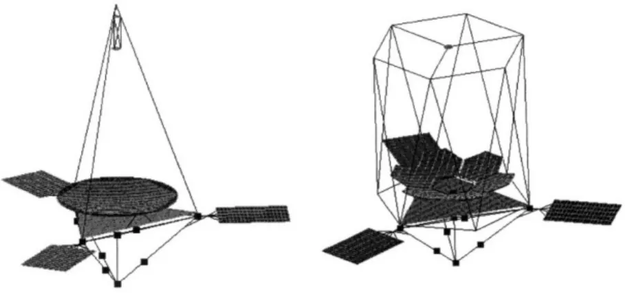
very greatly. For instance the primary mirror can be designed as a standard annular monolithic mirror by using the "Mono" module, but it can also be a segmented mirror with rib-stiffened hexagonal petals if the "Hex Isogrid" module is used. A completely different finite element model can be created by changing only a few of these inputs in the parameters file. Figure 2-3 shows two realizations of the MOST structural model. The telescope pictured on the left has a monolithic PM and a tripod SST, and the telescope on the right has a segmented PM and a hexapod SST. The mirror and SST type are the only two parameters which were altered in order to create these two very different models. The ease with which different telescope architectures can be created is an important feature of this model because it allows for large tradespaces to be generated quickly and automatically so that comparisons can be made.
Once the structural model has been generated for the chosen telescope architec-ture, a complete Nastran bulkdata structure is formed. The DOCS toolbox then generates an input file and calls Nastran to perform a normal modes analysis. The frequencies and modeshapes resulting from this analysis are then imported back into MATLAB.
Figure 2-3: Sample Architectures for Structural Model
2.1.2
Integrated Model
Using MATLAB, Nastran and the DOCS toolbox, an integrated model of the system is created as shown in Figure 2-4. Once the modes are imported into MATLAB, a state space system of the following form is created to represented the system dynamics.
0 q (2.1)
_Q-2
-2(Q
q
where q represents the modal coordinates of the system, Q are the frequencies resulting from the Nastran analysis, and ( is a modal damping ratio which can be varied. In order to fully represent the behavior of this system, a disturbance model, isolators and controllers are added to this model.
The on-orbit dynamic disturbances to this model are due to the imbalances in the reaction wheel assembly which are used for attitude control and slewing. The size of the reaction wheels will scale with the inertia of the spacecraft in order to maintain the same slew rates, and it is assumed that the imbalance inertia is proportional to the wheel inertia, so the disturbances will also grow as the spacecraft becomes more massive. This disturbance model consists of harmonics of radial and axial forces at discrete wheel speeds. Disturbance contributions at multiple wheel speeds are
Design variable inputs Figures of Merit outputs
Spacecraft form, dimensions Optical performance
Material / geometry properties Mass
Sub-system parameters Settle time
MATLAB NASTRAN MATLAB DOCS
G ]dpitcaclto mass MO K Dynamics modell Dynamic
Element connectivity normal modes assembly analysis
Figure 2-4: MOST Modeling Process
bined into power spectral density (PSD) curves representing the average disturbances across all frequencies. These can then be transformed to the spacecraft axes, and the disturbances from multiple wheels summed [16].
Isolators and controllers are added to the model as linear state space systems. Isolation is added to the system at two locations: between the reaction wheel assembly and the spacecraft bus and between the bus and the OTA. The isolators are modeled using low pass filters with variable corner frequencies. There are also up to four control systems for the spacecraft dynamics: an attitude control system (ACS), fast steering mirror control, dynamic piezoelectric wavefront control and petal control for the segmented mirrors. Various amounts of each of these types of control are used to create different control architectures for each telescope realization. These controllers
are not the focus of this work, and are only mentioned to complete the description of the integrated model [8].
2.1.3
Performance Metrics
Once the model has been created, the reaction wheel disturbances are used to perform a frequency-based dynamic disturbance analysis in order to determine the optical performance of the telescope. The first optical performance metric for this telescope is the line-of-sight (LOS) jitter. The LOS jitter can be thought of as errors in the image quality due to motions of the entire OTA. The LOS jitter is approximated using rotations and translations of points on the primary, secondary and tertiary mirrors:
1
(M-I1)
1
2
2
LOSz = + f6PY f S + ISyf + 2aPX 2 asX 2'x a+ T (2.2)
f,
MfJ
Mfi
M +1
M+ 1
1 (M-1) 1 2 2
LOSy = -6Px - s-- Tx -]+ 20py - Oasy OrTY
fM MflT MfP M +1l M + 1
where fi is the focal length of the primary mirror, M is the secondary mirror mag-nification, 6 is translation and ca is rotation for points on the primary mirror (P), secondary mirror (S), and tertiary mirror (T).
A LOS jitter requirement has been determined based upon the angular resolution of the system. The amount of jitter in the system must be small enough so that light from a point source is not blurred between pixels on a camera. The total LOS error requirement is then equal to the angular resolution:
1.22A
LOSeq = D (2.3)
where A is the wavelength of the imaged light and D is the primary mirror diameter; it was also assumed that dynamic disturbances account for 10% of the error. Therefore, for visible light (A = 600 nm) and a 3 meter diameter, the 3-a value for LOSeq is 1.6 mas.
The other optical performance metric is the wavefront error (WFE), which rep-resents the errors in the optical surfaces. In this model, the WFE is approximated based on the deformations of the primary mirror only [1]. Zernike polynomials are used to represent the primary mirror distortion. These are a sequence of polynomi-als in polar coordinates of radius, p, and angle, 0, which are orthogonal on a unit circle. The Zernike equations are defined in Reference [35], and the first few shapes are shown in Figure 2-5. The out-of-plane displacements of the mirror surface are decomposed into coefficients of the first 48 Zernike functions. The root sum square of the weighted coefficients is then the WFE.
WFE Z= ~ ~ (2.4) where zi is the coefficient of Zernike term i and wi is the weighting factor on this term.
The requirement for the WFE is:
A
WFE < - (2.5)
20
Again, it is assumed that this is a 3-a requirement and the dynamic disturbances are allocated 10% of the error budget. This results in a 1 nm requirement for the WFE.
Figure 2-5: Zernike Shapes
In addition to these optical performance metrics, the telescope is judged on higher level system metrics. The first of these is the slew and settle time. Each time the spacecraft needs to rotate to point to a new location, vibrations will be introduced, and some amount of time will be required for the telescope to settle to within the LOS requirement. The telescope will be unable to image until it settles, and so it can be thought of as out-of-operations during the time of the slew and settling. A time domain simulation is used to calculate the settle time after a slew.
The final performance metrics for the system are mass and cost. The structural mass is computed directly using Nastran, and concentrated point masses are used to represent instruments in the bus which are not modeled in detail. These masses are sized to scale with the rest of the system. The cost metric is extremely difficult to
model for a space telescope which incorporates so many new technologies. Mass is used as an indicator of launch cost, but the mass cannot represent other costs such as manufacturing. In order to capture the cost of manufacturing, a relative cost model was developed based on the cost models which exist for many ground-based telescopes
[29].
C oc nsgsDl.8sZ1
.04 (2.6) where nsegs is the number of segments in the primary mirror (one for a monolithic
mirror), D is the diameter of a segment, and Z is the primary mirror sagitta, which
is a function of the F# and the conic constant. The Z1.0 4 factor captures the costs
due to the polishing complexity which will vary according the the curvature of the mirror. This is purely a relative cost metric based on the manufacturing complexity of the mirror, and it will only be used for comparison between architectures. The LOS jitter, WFE, settle time, mass and cost are all used in the tradespace analysis to evaluate and compare many different telescope architectures.
2.2
Mirror Finite Element Model
A major component of this project is the structural model of a lightweight deformable primary mirror. Current state-of-the-art telescope designs have been developing pri-mary mirrors with areal densities approaching 10 kg/m 2 (measured without including
the actuators and supports) [20]. Therefore, a goal of the MOST project has been to model and analyze mirrors with areal densities in the range of 5 to 15 kg/m2, while maintaining fundamental frequencies above launch vehicle requirements. Due to tightening resolution requirements, large primary mirrors are of particular interest, so the primary mirror diameter is varied from three to five meters. The large scale of these mirrors makes it especially hard to achieve acceptable stiffness in the mirror without adding mass. In order to achieve these conflicting goals of large diameter, low mass and high stiffness, this thesis focuses on the modeling and analysis of the primary mirror.
A model for a lightweighted mirror is developed using a rib-stiffened mirror ge-ometry. The parametric model of this mirror is then used to study the effects of altering the geometry of the mirror and to optimize the structure for high stiffness to mass ratio. Since reduced stiffness, associated with lower areal densities, makes these mirrors more susceptible to thermal and dynamic disturbances, models of embedded actuators have been created in order to apply active controls which can improve the optical performance of the mirror. This section will discuss the modeling and finite element mesh generation of the primary mirror in greater detail. This model of the primary mirror will then be used, both as a part of the full MOST model and as a stand-alone model, to test the effects of parameter variation and to apply control laws.
2.2.1
Mirror Structure
As the diameter of the primary mirror continues to grow, the traditional monolithic mirror becomes increasingly difficult to launch using existing launch fairings. In addition, it was shown in Equation 2.6 that manufacturing cost scales with DL8. For
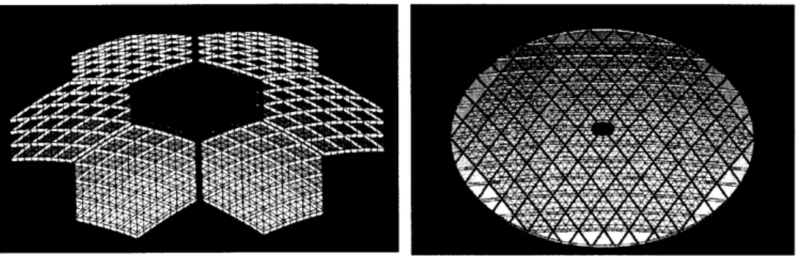
this reason, a segmented hexagonal mirror was modeled as well as the traditional annular monolithic mirror. Visualizations of these two mirror types can be seen in Figure 2-6. A segmented mirror can be launched in a stowed configuration and deployed on orbit, and the six identical segments are much cheaper to manufacture than one large mirror. The segmented mirror consists of six hexagonal mirror petals which are rigidly attached to a central ring. The central ring is formed using bar elements, and each segment is cantilevered from this ring using rigid elements. Larger segmented systems can be created by adding a second ring of segments; however, six is the largest number of segments which is studied in this thesis. Separate MATLAB modules exist in order to generate these different mirror geometries, and the type of mirror generated is based upon a user input in the parameters file.
As mentioned previously, the mirror is modeled with a diameter between three and five meters with an areal density between 5 and 15 kg/m 2. This number for
Figure 2-6: Segmented and Monolithic Mirror Models
mirror, it does not include the central ring or the attachments. The goal is for these lightweight mirrors to meet certain frequency requirements for launch. The entire primary mirror must have a fundamental frequency above 20 Hz and each segment of a segmented mirror must have a fundamental frequency above 100 Hz. In order to create a stiff mirror without adding a large amount of mass, a lightweighted mirror is modeled by incorporating rib-stiffening. As shown in Figure 2-7, the rib-stiffened mirror uses a triangular pattern of stiff ribs to support a thin face sheet which forms the optical surface. The tall, thin ribs on the back of the mirror create a very stiff structure without adding a large amount of mass.
hment
Y z
Figure 2-7: Back View of Rib-Stiffened Monolithic Mirror
Advanced materials are an important part of achieving the desired performance of the mirrors. Many current advanced telescope designs are considering using either
beryllium or silicon carbide for the primary mirror [17][18]. The important mate-rial properties are high stiffness to mass ratio, low coefficient of thermal expansion (CTE), high thermal conductivity and isotropic behavior. Stiffness to mass ratio is an important metric for dynamic performance, while a high conductivity to CTE ratio reduces the effect of thermal disturbances. Silicon carbide (SiC) is used throughout this project. It is a particularly good material choice due to its isotropic behavior, high stiffness to mass ratio, low coefficient of thermal expansion and high thermal conductivity. The material properties for SiC are shown in Table 2.1. One advan-tage of using a parametric model is that material properties for the mirror can be varied easily if there is interest in modeling a different material.
Table 2.1: Silicon Carbide Material Properties
Parameter Units Values
Modulus, E GPa 375
Density, p kg/rn3 3200
Poisson's Ratio, V kg/m 2 0.17
CTE ppm/°C 2.44
Conductivity, r W/moC 157
The monolithic mirror is connected to the secondary support tower by kinematic bipod mounts at three points spaced 120 degrees apart in the 0-direction; these sup-port points are chosen to be at the intersection of the ribs. In Figure 2-7, the connec-tion points are located at the three red dots. For the segmented mirror, the connecconnec-tion points are located at three points on the central ring. This kinematic mount fully constrains the six degrees of freedom of the mirror while allowing the mirror to stretch and shrink without warping. In the model, the three connection points are completely constrained in the vertical (z) and and circumferential (0) directions. Soft springs connect all other degrees of freedom, so that motions are not rigidly constrained. This system will non-redundantly constrain all six degrees of freedom, creating a kinematic mount. When the primary mirror is studied apart from the rest of the telescope struc-ture, the kinematic mount is modeled by applying a single point constraint in the z
and 0 directions only. By leaving the radial direction unconstrained, the mirror is free to expand and contract. In this way, the boundary conditions of a kinematic mount
are simulated for the mirror when it is analyzed apart from the telescope structure.
2.2.2
Mirror Mesh Auto-Generation
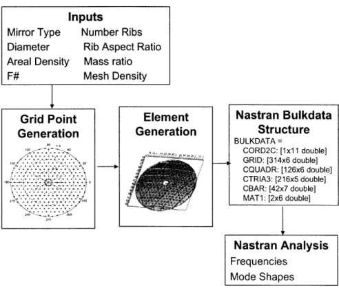
These structural mirror models are automatically generated by MATLAB functions. The inputs to these functions are the parametric inputs which define the mirror geometry, and the output is a bulkdata structure which is then used to create the finite element model in Nastran. This process is shown in Figure 2-8. Unlike most auto-mesh programs, the user does not need to interface with a graphical program. This allows the mirror finite element model to be created by a batch inputs file so that many geometries can be analyzed automatically.
I
Grid Point Generation 120. , o. . . . . 3o 24 30 a 270 Element Generation Nastran Bulkdata Structure BULKDATA = CORD2C: [lx 1 double] GRID: [314x6 double] CQUADR: [126x6 double] CTRIA3: [216x5 double] CBAR: [42x7 double] MAT1: [2x6 double]I
Nastran Analysis Frequencies Mode ShapesFigure 2-8: Mirror Mesh Generation Method
Depending on the user input for the mirror type, a function is called to model either the monolithic or segmented hex mirror. The mirror diameter, number of ribs and mesh density parameters are then used in order to calculate the locations of the grid
Inputs
Mirror Type Number Ribs Diameter Rib Aspect Ratio Areal Density Mass ratio
F# Mesh Density
points in the mesh. For the monolithic mirror, grid points are generated across the mirror surface so that triangular elements can be formed, and both an inner and outer diameter are created in order to form the circular shape. For the segmented mirror, a hexagonal segment is generated with the grid points in triangular patterns. These grid points are then copied to new locations to generate the remaining five mirror segments. The mirror modeled is parabolic, and the values for diameter and F# are used to compute the curvature. The z-direction locations of the grid points are then determined based on this curvature.
Once the grid points have been generated, elements are formed by connecting the grid points. The mirror is modeled using two dimensional plate elements for the ribs and the facesheet (CQUADs and CTRIAs in Nastran). The user is able to specify the desired areal density (in kg/m 2) of the mirror. In addition, the aspect ratio of
the rib cross section and the percentage of mass in the mirror facesheet are all inputs to the model. These inputs are used in order to determine the height and thickness of the rib elements and the thickness of the facesheet elements.
Once the element definitions have been generated, the Nastran bulkdata structure is written. This structure includes coordinate systems, grid point definitions, element definitions, property cards for the elements, and material property information. The output of the mirror generation code is this bulkdata structure as well as any necessary information about connection points.
Figure 2-9: Variable Mesh Density for a One Meter Diameter Hexagonal Segment In addition to the geometric parameters, the user can alter the finite element mesh density in order to improve the model fidelity. Figure 2-9 shows a one meter diameter
hexagonal segment with three rings of rib-stiffening and a varying mesh density. A ring of rib-stiffening is one hexagonal ring of rib elements. For instance, the mirror segment in Figure 2-9 has three rings of rib stiffening. The darker lines in this figure represent the rib structure and the lighter lines show the boundaries of each finite element. The user selects a desired number of elements per meter; however, the mesh generation code rounds this number so that there is a whole number of elements in a triangular rib cell. Figure 2-9 shows mirror meshes of (from left to right) 6, 18 and 30 elements per meter, which correspond respectively to 1, 9 and 25 triangular elements per cell.
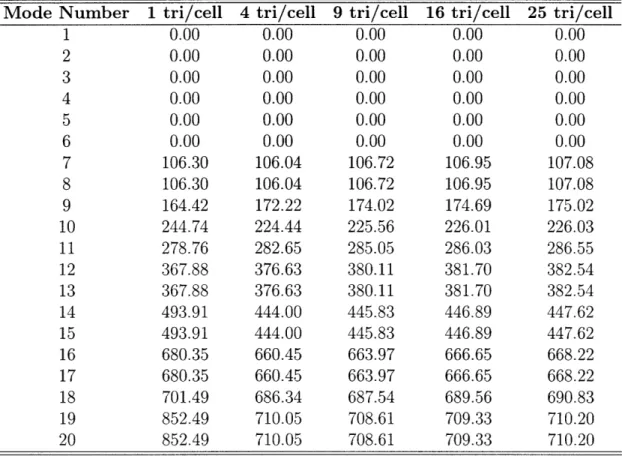
Table 2.2: First 20 Frequencies for One Meter Hexagonal Segment with Varying Mesh
Mode Number 1 tri/cell 4 tri/cell 9 tri/cell 16 tri/cell 25 tri/cell
1
0.00
0.00
0.00
0.00
0.00
2
0.00
0.00
0.00
0.00
0.00
3 0.00 0.00 0.00 0.00 0.00 4 0.00 0.00 0.00 0.00 0.00 5 0.00 0.00 0.00 0.00 0.00 6 0.00 0.00 0.00 0.00 0.00 7 106.30 106.04 106.72 106.95 107.08 8 106.30 106.04 106.72 106.95 107.08 9 164.42 172.22 174.02 174.69 175.02 10 244.74 224.44 225.56 226.01 226.03 11 278.76 282.65 285.05 286.03 286.55 12 367.88 376.63 380.11 381.70 382.54 13 367.88 376.63 380.11 381.70 382.54 14 493.91 444.00 445.83 446.89 447.62 15 493.91 444.00 445.83 446.89 447.62 16 680.35 660.45 663.97 666.65 668.22 17 680.35 660.45 663.97 666.65 668.22 18 701.49 686.34 687.54 689.56 690.83 19 852.49 710.05 708.61 709.33 710.20 20 852.49 710.05 708.61 709.33 710.20The effect of varying the finite element mesh was what mesh fidelity is required to obtain good results.
studied in order to determine The single hexagonal segment shown in Figure 2-9 is used to test the effect of the mesh refinement on the fundamen-tal frequencies of the mirror. Table 2.2 shows the first 20 frequencies of this mirror. Because this mirror was tested unconnected to the full telescope structure, the first
six frequencies represent rigid body modes and are equal to zero. To determine the amount of error caused by using a coarse mesh, the finest mesh model is considered to represent the exact solution. It can be seen that when only one element is used to represent a cell, the resulting frequencies have a large amount of error. For example, when there is one element per cell, modes 14 and 15 show a 10% error and modes 19 and 20 show an error of nearly 20%. If the mesh is increased to four elements per cell, the maximum error in these 20 modes is 2%, and if nine elements are used in a cell, the maximum error drops to 1%.
2.2.3
Piezoelectric Actuator Model
A goal of this project is to examine tradeoffs between lightweight structures and the use of active controls to minimize the effects of disturbances. In order to test the control laws, actuators must be included in the finite element model of the mirror. A surface-parallel-actuated mirror is created by embedding actuators in the ribs parallel to the mirror surface and away from the mirror facesheet, as shown in Figure 2-10 An axial strain is then induced in the actuators, causing a moment to be exerted on the mirror.
Su
PZT
u
t z
Figure 2-10: Piezoelectric Actuator Embedded in Rib
In Nastran, these actuators are modeled using CBAR elements connected to the rib elements using rigid RBAR elements, which have zero thermal conductivity. This
is necessary in order to thermally isolate the actuator from the remainder of the struc-ture. Piezoelectric actuation is used for this mirror, although many other possibilities exist for actuating the mirror. Voltage is applied to the piezoelectric material, and a strain results according to Equation 2.7.
V3
S= d33 (2.7)
t
where d3 3 is the piezoelectric constant, V is the applied voltage, and t is the thickness of the piezoelectric.
In order to model the piezoelectric effect in Nastran, a thermal analogy is used in which temperature is used to simulate voltage actuation, and the piezoelectric constant is represented by a coefficient of thermal expansion (CTE). However, when these actuators are used to correct the mirror shape under thermal disturbances, a problem arises. Now the CTE parameter must be used to represent the actual thermal expansion coefficient and also the piezoelectric constant [12]. This can be done by correctly scaling the input voltage.
V3 E = aT + d33' V(2.8) t d3 3 V3 E = a(T+ d33 V3 aTeff (2.9) a t
where ca is the CTE of the actuator, T is the temperature, and Teff is the effective temperature which is applied in the finite element model to account for both the thermal and voltage effects on the actuator.
Although this actuator model, including the thermal representation of the piezo-electric effect, is not important for the dynamic analysis of the lightweight mirror, it is a major component of the active control system discussed in Chapters 3, 4 and 5.