ADDITIVE MANUFACTURING
OF OPTICALLY TRANSPARENT GLASS
JOHN KLEIN
BACHELOR OF ARCHITECTURE
SOUTHERN CALIFORNIA INSTITUTE OF ARCHITECTURE (SCI-ARC 2010)
Submitted to the Program in Media Arts and Sciences, School of Architecture and Planning, in partial fulfillment of the requirements for the degree of
ARCHIVES
Master of Science MASSACHUSETTS INSTITUTE
at the OF TECHNOLOGY
MASSACHUSETTS INSTITUTE OF TECHNOLOGY
NOV
2 5
2015
September 2015
LIBRARIES
Massachusetts Institute of Technology 2015. All rights reserved.
AuthorSignature
redacted
John Klein Progr in Media Arts and Sciences
/A)
igu)t , 2015Certified by
Signature redacted
/
ProfessorAferi
Oxman Associate Pr a Art and Sciences esis AdvisorAccepted by
Signature redacted
YJr-Q cia Maes Associate Academic Head Program in Media Arts and Sciences
ADDITIVE MANUFACTURING
OF OPTICALLY TRANSPARENT
GLASS
JOHN KLEIN
Submitted to the Program in Media Arts and Sciences, School of Architecture and Planning, on August 7, 2015, in partial fulfillment of the requirements for the degree of Master of Science
ABSTRACT
The thesis presents an Additive Manufacturing Enabling Technology for Optically Transparent Glass. The platform builds on existing manufacturing traditions and introduces new dimensions of novelty across scales by producing unique structures with numerous potential applications in product-, and architectural-design. The platform is comprised of scalable modular elements able to operate at the high temperatures required to process glass from a molten state to an annealed product. The process demonstrated enables the construction of 3D parts as described by Computer Aided Design (CAD) models. Processing parameters such as temperature, flow rate, layer height and feed rate, can be adjusted to tailor the printing process to the desired component; its shape and its properties. The research explores, defines and hard-codes geometric constraints and coiling patterns as well as the integration of various colors into the current controllable process, contributing to a new design and manufacturing space. Performed characterization of the printed material to determine its morphological, mechanical and optical properties, is presented and discussed. Printed parts demonstrated strong adhesion between layers and satisfying optical clarity. The molten glass 3D printer as well as the fabricated objects exhibited, demonstrate the production of parts which are highly repeatable, enable light transmission, and resemble the visual and mechanical performance of glass constructs that are conventionally obtained. Utilizing the optical nature of glass, complex caustic patterns were created by projecting light through the printed objects. The 3D printed glass objects and process described here, aim to contribute new capabilities to the ever-evolving history of a very challenging but limitless material - glass. Thesis advisor:
Professor Neri Oxman
ADDITIVE MANUFACTURING
OF OPTICALLY
TRANSPARENT
GLASS
JOHN KLEIN
Submitted to the Program in Media Arts and Sciences in partial fulfillment of the requirements for the degree of Master of Science in Media Arts and Sciences
'N
Signature redacted
YIeai J. J in Yooneead of the D artment of Architecture Massachusetts Institute of Technology
ADDITIVE MANUFACTURING
OF OPTICALLY
TRANSPARENT
GLASS
JOHN KLEIN
Submitted to the Program in Media Arts and Sciences in partial fulfillment of the requirements for the degree of Master of Science in Media Arts and Sciences
Signature redacted
Professor Neil GerslfenfeldDirector, Center for Bits and Atoms Massachusetts Institute of Technology
ACKNOWLEDGMENTS
First and foremost, I would like to thank one of the most influential people in my life whom I'm privileged to have as a mentor: Neri Oxman. Neri thank you for all your support and encouragement over the last two years, my experience in the Mediated Matter Group has changed the way I think and see the world.
Meejin Yoon, thank you for providing the architectural framework through our meetings and conversations, which guided the way I structured my work in the Media Lab. Your practice is one I aspire to as an architect.
Neil Gershenfeld, thank you for your guidance and encouragement throughout my time here at MIT. My most enjoyable memories are from my time down in the Center for Bits and Atoms, and your way of thinking about making has left a permanent mark on me.
John Ochsendorf, it has been an honor to engage with you here at MIT, as your work was one of the reasons which drew me into the community. I look forward to collaborating together on the large scale glass structure!
Peter Houk, not only have you and the MIT Glass Lab been an incredible source of inspiration for my thesis, you have always been someone I could reach out to at any time and count on. It has been a true pleasure to collaborate together over the last 2 years.
Markus Kayser, out of all the people in the Mediated Matter Group, I've worked together closely with you over the last two years. Thank you for making this experience one of the most intellectually stimulating periods of my life. I've never met anyone who has such a unique way of perceiving the world. Your work on the solar sinter had set the tone for my interests in the group, and I'm confident we will continue to collaborate for years to come.
Chikara Inamura, we've worked together now in Asia, Europe and America for over 10 years, and every project that we put our heads together has turned out to be my best work. I very much look forward to kicking off the next season of IIK.
Will Patrick, you and I entered the MIT journey together trapped in a small remote office, and built a genuine friendship through our curiosities that blended design and engineering.
Steven Keating, not only have you made me step out of every comfort zone I've ever built prior to joining the group, the strength and courage I witnessed through you will stay with me for the rest of my life. Thank you for pushing me to technically challenge myself in ways I never
thought I could achieve, and thank you for your generous gifts of maple syrup from your hometown in Canada.
Giorgia Franchin, thank you for joining the Mediated Matter Group and being my partner in crime on the glass printing project. I've been fortunate to share this unique, close collaboration, between a material scientist and an architect, and this has proved to be one of my most valuable experiences here at MIT.
Kelly Donovan, thank you for everything you have done for me throughout my time in Mediated Matter Group! Your support, guidance, advice and retreats to the Rebel Ranch Horse Farm made my MIT experience possible.
Sunanda Sharma, Jorge Duro-Royo, Laia Mogas-Soldevila, Daniel Lizardo, thank you all for your comradery and friendship. I couldn't have asked to work with a more talented group of
individuals over the last two years.
James Weaver, your inspiration and knowledge about the entire world is simply unprecedented. Thank you for all the meetings at your office in the WYSS to discuss the exciting
intersection of materials and biology. You are truly one of a kind.
Will Langford, thank you for all the fabrication, material, physics, mechanical, electrical, robotic, cooking and baking knowledge you have shared with my over the last two years! Your always are a genuine source of inspiration for me and I very much value our friendship.
Michael Stern, the collaboration with you over the past two years has not only been incredibly fruitful, but you have changed the way that I approach design. It is very rare that an architect and mechanical engineer work together at such a "high bandwidth", and your sense of pragmatic logical thinking grounded my work and made the G3P project come together.
Erik & Marty Demaine, thank you for your support and sense of humor in the glass lab when things would catastrophically go wrong. Your jokes and playful spirits always put a smile on the team's faces when we were in need.
John DiFrancesco, Tom Lutz and Seth Cimarron Avecilla, thank you all for all the support down in the Fab Lab. As you could probably tell by the amount of hours I spent in the shop, it is my most favorite space in all of MIT. Thank you for supporting every project I brought down, and your willingness to help me realize my visions.
Kevin Davis, Cornelle King and Jessica Tsymbal, thank you three for all your efforts and support in helping our team realize the MIT Media Lab "Glass" Exhibition. Your dedication, and
do-whatever-it-takes attitude to ensure quality projects, has enabled our group to grow through each exhibition.
Linda Peterson, Keira Horowitz, thank you both for all your help during my time here in the MIT Media Lab. Your willingness to always look after our whole cohort and take the time to make sure that I am on track is greatly appreciated.
Corning Incorporated, thank you for inspiring and hosting our team in Corning's headquarters, Sullivan Park and the Corning Museum of Glass. I've learned an incredible amount of knowledge about the rich history of glass through the trip that has greatly influenced my thesis. Lorna Gibson, thank you for opening my eyes to the incredible world of material science. Your course was -hands down -the most challenging experience I've ever went through in my entire life. It was also equally the most rewarding. Thank you for all your support taking the time to sit in your office to share your knowledge and passion.
I'd like to thank Zaha Hadid and Patrik Schumacher for all the incredible opportunities you provided me during my five years at ZHA. Thank you for believing in me, and not thinking twice to throw me in the fire(s) all over the world.
I'd, also like to thank the highly influential people who shaped my career as an architect: Cristiano Ceccato, Satoshi Ohashi, Armando Solano, Michael Grau, Shajay Bhooshan, Eric Owen Moss, Marcelo Spina, Peter Testa, Elena Manferdini, Alexis Rochas, Mark Burry, Jane Bury, David Gerber, Sanford Kwinter and Steven Cohen.
Last, but far from least, I would like to thank my family. I cannot even begin to express how thankful I am to everyone and how grateful I am to have come from such a genuine group of people. Thank you for everything you have ever done for me and all your encouragement. This thesis is dedicated to all of you.
CONT ENTS
INTRODUCTION & BACKGROUND 20
1.1. Glass 20
1.1.1. History & Context 20
1.1.2. Properties Of Glass 21
1.1.3. Glass Applications & Advances 24
1.1.3.1. Architectural Windows 24
1.1.3.2.
Lenses 261.1.3.3. Automated Glass Forming 27
1.2. Additive Manufacturing 29
METHOD A: GLASS SINTERING 33
2.1. Direct Spark Sintering 33
2.2. Lichtenberg Sintering 36
2.3. Laser Sintering 39
METHOD B: GLASS FDM 42
3.1. System Design And Construction 42
3.1.1. System Implementation 42
3.1.2. Hardware 45
3.1.2.1. Heating Elements 45
3.1.2.2. Frame And Carriage 49
3.1.2.3. Motors And Bearing Blocks 50
3.1.2.4. Safety Measure 51
3.1.3. Software 52
3.1.3.1. Cad Model 52
3.1.3.2. Slicing And Generating G-Code 53
3.1.3.3. Motion Control 54
3.2. System Operation Characterization 55
3.2.1. Material Characterization 55
3.2.2. Process Characterization 56
3.2.2.1. Temperature Distribution 56
3.2.2.2. Physics Of Glass Flow 58
3.2.2.3. Flow Estimation 60
3.3. Fabrication Of 3d Printed Glass Parts 61
3.3.2. Parameters Calibration And Design Space 63
3.3.3. Falling Fluid Deposition 66
3.3.4. Colored Glass Printing 67
3.4. Characterization Of 3d Printed Glass Parts 69
3.4.1. Scanning Electron Microscopy (Sem) 70
3.4.2. Residual Stresses - Polariscopy 70
3.4.3. Preliminary Mechanical Testing 72
3.4.4. Optical Properties 73
3.5. Limitations And Future Work 81
CONCLUSIONS 86
AUTHOR DISCOLOSURE STATEMENT 89
REFERENCES 90
LIST OF FIGURES
Figure 1: Egyptian glass blowing; Float glass; Hale telescope ... 20
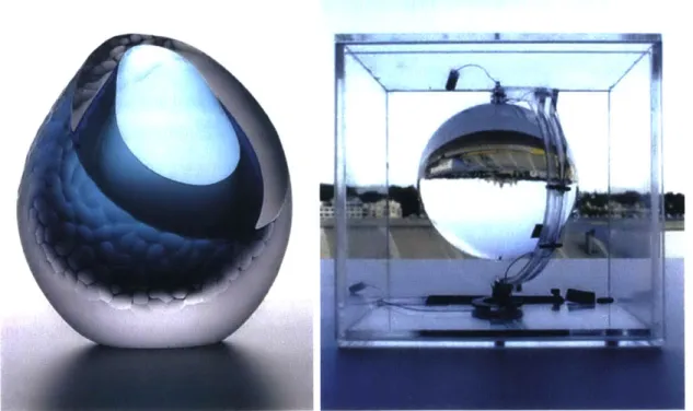
Figure 2: Sculptural glass design; Spherical solar concentrators ... 21
Figure 3: Ashby Charts; Soda-lime glass m aterial profile... 23
Figure 4: Crystal Palace in London; Forming cylindrical glass tubes ... 24
Figure 5: Float Glass m anufacturing process ... 25
Figure 6: Galileo Galilei using his telescope; Robert Hooke using his m icroscope... 26
Figure 7: Owens Bottle M achine; Thom as Edison's first light bulb ... 27
Figure 8: ExOne/Shapeway sintered glass...29
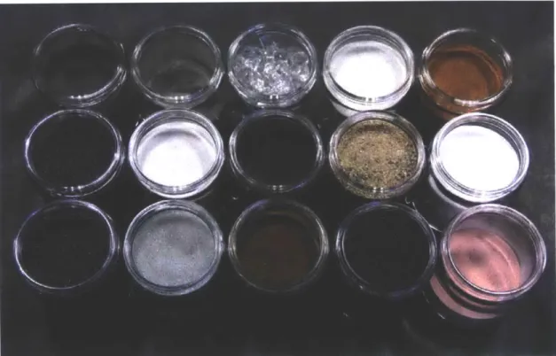
Figure 9: Varying glass com position ... 33
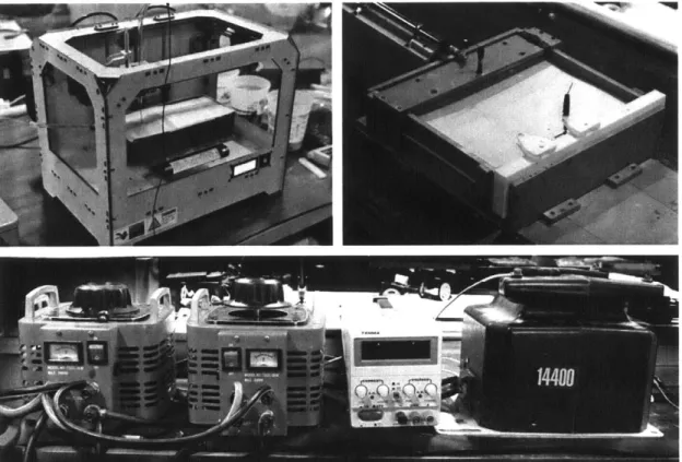
Figure 10: Sintering test setups ... 34
Figure 11: Electrosintering experim ents...35
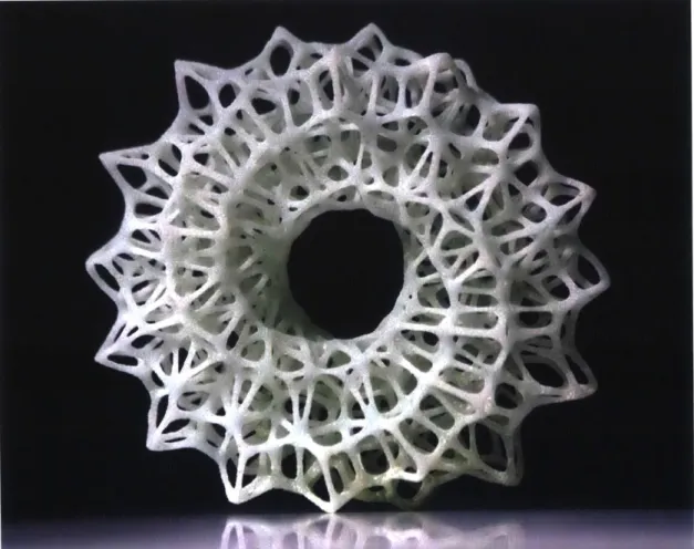
Figure 12: Sintered glass Lichtenberg structure... 36
Figure 13: SEM of the Lichtenberg glass fusion details...38
Figure 14: SLS glass experiments ... 39
Figure 15: Deposited glass powder...40
Figure 16: Evolution of the FDM glass printing process...42
Figure 17. Rendered cross-section of the FDM system ... 45
Figure 18: Platform hardware...47
Figure 19: Depositing m olten glass into the Print Annealer... 48
Figure 20: The assembled printer frame & carriage ... 49
Figure 21: Stepper m otor connected to ACM E lead screws ... 50
Figure 23: 3D design space ... 52
Figure 24: G3P custom G CO D E Generator...53
Figure 25. Experim ental viscosity data and resulting VTF equation ... 56
Figure 26. Tem perature distribution ... 57
Figure 27: M olten glass flow ... 58
Figure 28: M olten glass exiting out of the nozzle at T -990*C... 60
Figure 29. M olten glass at T -990'C ... 64
Figure 30. Objects printed using the platform ... 66
Figure 31. Falling Fluid D eposition ... 68
Figure 32. D etail of a colored printed object...69
Figure 33: Characterization of the printed parts... 72
Figure 34. 3 points bending tests...74
Figure 35: O ptical properties and caustic patterns of printed parts... 75
Figure 36: Caustic patterns ... 76
Figure 37: Caustic patterns ... 77
Figure 38: Caustic patterns ... 78
Figure 39: Caustic patterns ... 79
Figure 40: Caustic patterns ... 80
Figure 41: 3D Printing vs Press M anufacturing ... 80
LIST OF TABLES
Table 1. Glass 3D Printer evolution steps...43
Table 2. System 96® Studio Nuggets TM density and CTE estim ations...55
Table 3. Flow resistance in the crucible and nozzle assembly... 60
Table 4. Annealing cycle. ... 62
Table 5. Printed objects param eters and features. ... 65
INTRODUCTION & BACKGROUND
1.1. GLASS
1.1.1. HISTORY & CONTEXT
Figure 1: (A-top left) A painting of a carving from the tomb of Akhti-Hotep and Ptah-Hotep which shows early Egyptian glass blowing. Image source: Italmole S.N.C (B-bottom left) Pilkingtonfloat glass process. Image source: Corning Museum of Glass (C-right) Hale telescope at Palomar Observatory made from Pyrex. Image source: Corning Museum of Glass
Ancient yet modern, enclosing yet invisible, glass was first created in Mesopotamia and Ancient Egypt 4,500 years ago. Precise recipes for its production -the chemistry and techniques
- often remain guarded secrets. Glass can be molded, formed, blown, plated or sintered; its formal qualities are closely tied to techniques used for its formation.
The story of glass is largely about people overcoming limitations imposed by substantial difficulties inherent in the material itself. Among these difficulties are achieving and sustaining the elevated temperatures necessary to melt and form glass, developing methods of forming glass without being able to touch it with the human hand, and the problem of thermal shock (resulting in cracking or catastrophic failure).
From the discovery of the core-forming process for bead-making in ancient Egypt (Figure
1A), to the invention of the metal blow pipe during Roman times, to the modern industrial
Pilkington process for making large-scale flat glass (Figure 1B), to lenses that enabled human kind to see down into the petri dish and out into the universe (Figure 1C), and to the drawn
fibers that revolutionized the way humans communicate across the planet, each new breakthrough in glass technology occurred as a result of prolonged experimentation and ingenuity, and has given rise to a new universe of possibilities for uses of the material.
The thesis presents an Additive Manufacturing Enabling Technology for Optically Transparent Glass, which builds on existing manufacturing traditions and introduces new dimensions of novelty across scales by producing unique structures with numerous potential applications in product, and architectural design.
In other words, the thesis aims to contribute to a quantum context - ever-evolving, constantly breaking through limitations in order to discover new capabilities of this very challenging but limitless material.
1.1.2. PROPERTIES OF GLASS
Figure 2: (A-left) Artist Joanne Mitchell's sculptural glass design. Image source: North East Art Collective (B-right) Andri Broessel's spherical solar concentrators. Image source: Inhabitat weblog
Glass continuously converts into liquid upon heating, and has an amorphous structure with a random molecular organization39,41. Soda-lime glass (a form of glass that is used world-wide) is primarily obtained from the melting of 70% sand (silica), 15% soda ash (sodium carbonate)
and 5% limestone (calcium carbonate)39,41. This raw material mixture is commonly referred to as "batch," and has not changed dramatically since the Egyptians39.
Glass' random molecular structure impacts its material behavior under different temperatures. Soda-lime glass has a working range between 1000'F -1700'F which enables a slow transition from a solid to a liquid state39. This working range enables glass to have its unique forming capabilities such as molding, slumping, fusing and blowing39.
Since glass is an inert chemically stable substance (in its application environment) with high durability it is manufactured in large volumes as containers, vessels and laboratory equipment for the food and drug industry to prevent contamination to sensitive products.
Glass' capacity to refract and reflect light give it very appealing optical properties (Figure 2A) 41. When light travels through glass that is formed into different convex and concave
geometries, it will deviate (refract), and focus, which causes the formed glass to exhibit properties of optical magnification (Figure 2B)37.
Electronic components are often integrated with glass, due its good electrical insulation properties and its ability to withstand heat.
A property profile of glass can be seen in (Figure 3) which shows the specific values for the mechanical, thermal, electrical and eco properties (for the material and molding processes). Three Ashby charts are also shown to situate the strength vs density, strength vs toughness and energy content vs cost against other material classes. The charts show that while glass is brittle with very little toughness, it has a higher compressive strength than concrete, and requires large amounts of energy for its forming and shaping processes34.
Chemical processes and composites were developed over the 20th to further augment the properties and performance of glass such glass and polymer laminations (for safety glass), heat treating and chemical tempering (to increase the compressive strength and control shattering), and tin oxide coatings (to allow light to pass through but not heat) 37.
As a result of glass' material properties, and advances in manufacturing process, it has made its way into numerous industries with varying applications. Most notable are the architectural, automotive, aerospace and medical industries.
3NO 1 st 13 0 3 m
OwmftmI" #b-v -""*
**0j
0.1 1 10 Two mOUGpu1E .9/.2 seu -+
General properties Values lUnits
Density 2,400 - 2,490 Kg/M3
Price 0.8 - 1.7 USD/kg
Mechanical properties
Young's modulus 68-72 GPa
Yield strength 30-35 MPa
Tensile strength 31-35 MPa
Elongation 0 %
Hardness -Vickers 439 -484 HV
Fatigue strength (107 c) 29.4 -32.5 MPa Fracture toughness 0.55-0.7 MPa m12 Thermal properties
Max. service temp. 443 -673 K T. conductor or insulator Poor insulator
T. conductivity 0.7- 1.3 W/m - K
Specific heat capacity 850 -950 J/kg -K
T. expansion coefficient 9.1 -9.5 pstrain/*C
Electrical properties
E. conductor or insulator Good insulator
Electrical resistivity 7.9x10¹⁷ -7.9x10'8 pohm - cm Dielectric constant 7- 7.6
Dielectric strength 12 -14 106 V/m
co propertes: imaterial
Global production 84 x 106 m. ton / yr
Reserves 1 x 10¹² m. ton
Embodied energy 10-11 MJ/kg
C02 footprint 0.7-0.8 Kg/kg
Water usage 14- 20.5 L/kg
Eco-indicator 75 millipoints/kg
Eco properties: processing
Glass molding energy 8.2-9.2 MJ/kg
Glass molding C02 0.66-0.73 kg/kg
End of life
Embodied energy 7.4-9.0 MJ/kg
recycling
C02 footprint recycling 0.44-0.54 kg/kg
Recycle fraction in supply 22 -26 %
Figure 3: Ashby Charts (top left) Strength vs Density (middle left) Strength vs Toughness (bottom left) Energy Content vs Cost. Image source: University of Cambridge, Department of Engineering (right) Soda-lime glass material profile. Table source: Materials and the Environment'
foes o 10 1b00 toem
F
4
'
..
1.1.3. GLASS APPLICATIONS & ADVANCES
1.1.3.1. ARCHITECTURAL WINDOWS
Figure 4: (A-left) Front view of the Crystal Palace in London. Image source: Former Days (B-right) Rendition of a glass factory forming cylindrical glass tubes for window applications. Image source: Diderot Encyclopedia, Glass
Windows have been a fundamental architectural design feature as early as the Romans, and function to establish relationships with the building's interior and exterior volumes, and let light, heat and air indoors. It is inevitable that glass has been a sought out material choice for windows given its optical properties and durability. Advances in building and manufacturing technology enabled windows to evolve from fenestrations in architectural envelopes to entire transparent building skins.
One of the most notable architectural-engineering glass building precedents is the Crystal Palace (Figure 4A), which was constructed in 1851 in Hyde Park, London. Prior to this project, glass panes were manufactured through a technique of blowing large glass bubbles, then rotating them to form a flat pane (also known as a crown)37. The crowns were then annealed
and subdivided into rectangular window panes37.
The Crystal Palace used an alternative technique to make its 300,000 glass panes bigger, which involved swinging a large glass bubble instead of spinning it, to form long cylindrical tubes (Figure 4B)37. The tubes were then sheared and unrolled flat, or curved to form the glass enclosure for the Palace37. This was an intensive and laborious manual process37.
Smnai pte LIrge plate Ift-offdevices Ift-off devices Cross cuitters Continnotts ribbon of glass cooling IOUr (coating chamnber) F11m, bathD Melting furnaceW1 Ma<Imwnasswnh <2387mmi I
Raw materal feed
Figure 5: A diagram showing each step in the Float Glass manufacturing process. Image source: NSG Group
The demand for window panes increased throughout the late 19th century, which lead to the development of more efficient ways to manufacture flat sheets of glass. Initial attempts in manufacturing flat glass include Emile Foucault's vertical glass draw tower and the Pilkington Brother's (with Ford Motors) horizontal drawn twin-grinding process 37. These techniques left
defects on the glass and required large amounts of energy to polish37.
In 1959 Pilkington Brothers came up with a process that fundamentally transformed the manufacturing output of glass: The Float Glass Process37. This process flows molten glass onto a liquid tin bath (Figure 5)37. Glass floats on top of the bath of tin, and eliminates the need for any energy intensive polishing processes37. The drawn glass sheet passes through an annealer
to relieve internal stresses and is then cut down to the desired panel sizes37.
The float glass process enabled glass to become a wide spread material with automotive windshields and faeade glazing systems as its primary applications. This manufacturing process has fundamentally transformed architectural design during the 20th century with the
ubiquitous implementation of the unitized glass curtain wall system on high-rise towers across the world.
1.1.3.2. LENSES
Figure 6: (A-left) Galileo Galilei using his telescope to study the sky. Image source: Lab Spaces (B-right) Robert Hooke discovering cells through his microscope. Image source: History of the Microscope
Glass' ability to manipulate light waves augmented human's capacity to see a new range of scales: from down into the petri dish to out in the vast depths of the universe. In the beginning of the 17th century lenses were invented, and Galileo Galilei developed a telescope, which he used to study the heavens (Figure 6A) 37. Seeing into the depths of space, Galileo discovered
the stars and geographical information about the moon37.
In the late 17th century Antonj Van Leeuwenhoek was able to see spores by developing a microscope that had a spherical lens3 7
. These technologies led to Robert Hooke's compound microscope, which he used to discover cells (Figure 6B) 37. Hooke's microscope had three lenses: the first outer lens collected the light, the internal two created the magnification effect to see the formed image37
The new glasses in which humans had to see the world, drove technological developments in the field of optical lenses, through human desires to see deeper, farther and clearer. Most notable inventions were the following: Sir Isaac Newton's reflecting telescope which used mirrors to provide optical clarity,
J.
Franklin Hyde's process to create fused silica from igniting silicon tetrachloride gas / silicon rich gas, applied in the production of space shuttle windows and telescope mirrors, Augustin Fresnel's Fresnel lens technology that reflected and refracted light to create car and traffic headlights, to lighthouse lenses, and glass fibers used for optical communication systems across the world37.1.1.3.3. AUTOMATED GLASS FORMING
Figure 7: (A-left) A concept drawing of the Owens Bottle Machine. Image source: University of Houston (B-right) Thomas Edison'sfirst light bulb. Image source: National Park Service
During the late 19th century, the industrial revolution brought automated processes into manufacturing pipelines through the rise of machines. The glass industry was one of the last domains to benefit from machine automation due to the levels of difficulty associated with handling the material37.
Michael
J.
Owens received the patent in 1904, for the Owens Bottle Machine (Figure 7A), a manufacturing technology that could automate bottle making, rendering conventional labor-intensive techniques obsolete37. The American Society of Mechanical Engineers, proclaimedthe technology as, "The most significant advance in glass production in over 2,000 years3 7."
Owens proceeded to form Owens-Illinois Glass Company, which would turn out to be one of the most influential shapers of the glass industry we know today37.
Thomas Edison developed the light bulb in 1879 (Figure 7B), and realized he needed a glass vessel to house his slow-burning filament37. The concurrent development of automated bottle machinery enabled gob forming techniques to be translated to the high-throughput
manufacturing of glass light bulbs3 7. William Woods was the inventor who pioneered the
technology in 1922: The Ribbon Machine37. The machine poured glass into a mold that output a ribbon of glass blanks, which was then met with blowing tips to inflate the bulbs42. To this
While the integration of automated processes with glass forming techniques has enabled more efficient material processing and higher manufacturing speeds, what we are able to make with glass is tightly coupled with the way we make it. The reality is, the forming techniques humans use haven't evolved much since the ancient Egyptian era: we still blow, mold and cast glass.
However, the past few decades have seen a rise in complex fabricated products due to innovations in the field of Additive Manufacturing.
1.2. ADDITIVE MANUFACTURING
Figure 8: ExOne/Shapeway sintered glass via binderjetting process. Image source: Desktop Engineering
Additive Manufacturing (AM) has undergone significant developments since its conception as documented by Charles Hull in his patent of 1984 for the construction of parts using a photo-crosslinkable polymer'. Numerous processes have since been introduced, as summarized by the American Society for Testing and Materials (ASTM) which defined seven categories according to which the wide range of processes can be classified2. Each of the various approaches relies on different physical characteristics and phenomena, and is often associated with specific materials.
Throughout the history of manufacturing, the design process has often been guided by the constraints of the fabrication method. Current freeform fabrication capabilities enable a more flexible design space: fewer design constraints provide entirely new opportunities for the construction and assembly of objects at different length scales. Specifically, additional
complexity in product scale is now possible without negatively affecting its production rate, cost, or quality. Furthermore, AM allows for simple, rapid, and economic design iteration, capitalizing on the efficacy of non-linear design and optimization.
Extruded material built in three dimensions has proved its commercial value with the development of an entire consumer-level industry based on the principles of Fused Deposition Modeling (FDM)3. However, FDM printers, in their current embodiment, are unable to handle high melting point materials, and require feeding the material in filament form, thereby presenting significant limitations in size and scale1.
Two 3D printing methods are typically used for higher melting point materials, such as metals and ceramics. The first one consists of a sintering method where particles are fused together below the melting point temperature. Parts are generally printed via binder jetting on a powder bed, where a binding agent temporarily joins particles until they are sintered through bulk thermal treatment4 (Figure 8). The second method uses a laser (Selective Laser Melting, SLM) or another thermal source to melt material particles that are either injected or present on the building platform5,6.
Glass-based materials hold the potential to provide particular value in the additive manufacturing field due to their hardness, optical qualities, affordability and availability. To date, binder jetting approaches have been applied to glass materials in order to overcome their
high melting temperatures and high viscosity4,7,8. Sintered glass objects printed in this method
are commercially available, but they are extremely fragile and appear opaque due to the light scattering from glass powders caused by incomplete densification (Figure 8) 9.
Robocasting has also been investigated for the manufacturing of glass components, with particular interest in Bioglass@ formulations for bone tissue engineering. In this process, glass particles are suspended in an aqueous solution or incorporated into a binder matrix. The mixture is then extruded through a nozzle to form a porous green body. As the green body undergoes sintering however, it encounters the same limitations of the binder jetted glass parts
described previously- 1 2.
Moreover, even the most recent experiments with glass SLM have not been able to overcome such issues: products remain opaque and show poor mechanical properties. Furthermore, polishing requires extensive effort, access to all geometry and often results in the samples breaking into smaller pieces. Even when successful, internal porosity leads to significant light scattering, thus limiting transparency when implementing this method13. A
manual wire feeding approach described in the same work yielded higher quality results; however, lack of automation limits control and prohibits part production.
The extrusion of molten glass remained in traditional glass manufacturing practices. In fact it is still applied in the artistic milieu: commercial kiln packages such as Bullseye Glass Co.'s Vitrigraph, enable glass artisans to create glass canes or stringers through manual glass extrusion, ranging in diameter from fractions of a millimeter to several millimeters14.
Large scale manufacturing processes have also been developed for glass extrusion; they are particularly suitable for glass characterized by a narrow working range and a very high softening point; such as silica glass (softening point -1600'C) or with a strong tendency to crystallize such as borosilicates. The application of pressure to force glass flow through a dye extends the glass working range to higher viscosities, and enables the production of rods and tubes with complex sections".
The following chapters will present the development of tools and processes, which culminated in the first of its kind fully functional material extrusion system for optically transparent glass, along with initial explorations in glass sintering. This enabling technology and related
platform is comprised of scalable modular elements able to operate at the high temperatures required to process glass from the molten state to the final annealed product. Automated
extrusion of 10 mm diameter glass beads with a build rate of about 460 mm3/s enabled the
creation of 3D parts as described by Computer Aided Design (CAD) models with a build volume of 250 mm x 250 mm x 300 mm.
The additive manufacturing system and printed parts provide proof-of-concept for automated glass deposition and the ability to produce objects within an expansive design space. This method enables production of parts that are highly repeatable, allow light transmission, and resemble glass as conventionally produced. Printed components can be modular and scalable from artistic products to architectural constructions, as it can be seen by the examples included herein.
Chapter 2
METHOD A: GLASS SINTERING
The Lichtenberg and Direct Spark Sintering technique that is discussed in Method A: Sintering Glass has been developed by Steven Keating, PhD Candidate from the Mediated Matter Group. All work presented in the following chapter has explored techniques from Steven's research.
METHOD A: GLASS SINTERING
2.1. DIRECT SPARK SINTERING
Figure 9: Varying glass compositions collected to experiment with additive sintering processes: Soda-lime glass #13-104 grits, recycled soda-lime glass, borosilicate, boromax frits, Moroccan sand, quikrete aggregate, black sand, magnetite sand, lunar and martian regolith
While numerous approaches exist to utilize heat to solidify glass, the research explored three sintering techniques with potential for ease of automation and form generation. These methods include 1) direct spark sintering, 2) a novel process termed Lichtenberg Sintering (by Steven Keating) that was inspired by the fractal geometry inherent to the technique and 3) Selective Laser Sintering. A range of glass samples were collected to explore the sintering processes ranging from soda ash glass, glass boromax frit, glass beads fine-coarse and varying compositions of raw sand (Figure 9).
Figure 10: (A-top right) Test bed high voltage setup (B-top left) Modified makerbot replicator 2for sintering (C-bottom) Single axis drive rail setup to sinter mechanical testing samples
Through initial experiments, the direct spark electrosintering fabrication approach has demonstrated a capacity to sinter the granular materials (35-88 micron soda ash glass powder) rapidly using high voltages and power in excess of 1 kW. The test bed high voltage setup is comprised of a 220V 60A variable autotransformer and a 14,400V line transformer (Figure 10A). There are two different methods to form members using electro-sintering: the one electrode drag (1ED) and the two electrode drag (2ED) techniques. The 1ED and 2ED setups were tested on a modified makerbot replicator 2 (Figure 10B) and on a single axis rail driven with a low voltage linear actuator (Figure 10C).
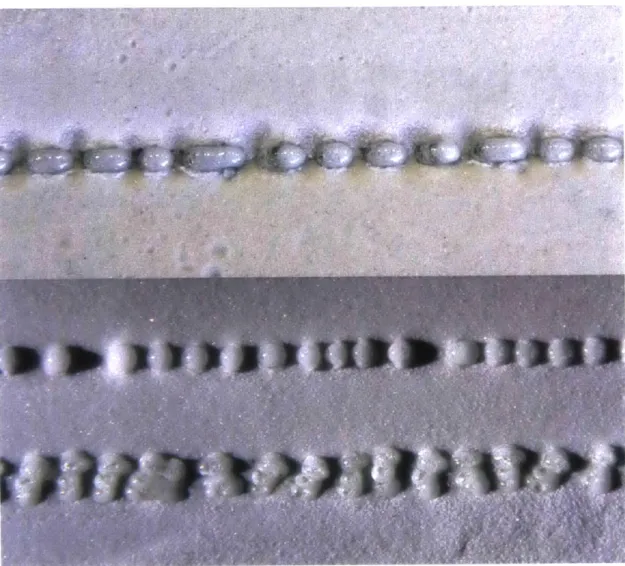
Figure 11: (A-left) Electrosintering experiments using direct spark sintering allows for designed structural members to be formed additively with controlled geometries (B-top right) Path bridging effect (C-bottom right) Member resolution and material build up
The
1ED
leaves the first electrode static while dragging the second electrode through the granular mixture. This maintains a live current running through the drag path and continually increases the thickness of the member due to the dissipation of heat. Large member elements have been produced with a rod diameter of around 0.75" (Figure 11A). The 2ED method pulls the two electrodes through the granular mixture together, which sinters the material between the two electrodes in a more controlled manner. (Figure 11B) shows a path bridging effect that occurs when the print path overlaps on itself, causing the electricity to find the minimal path of least resistance. This technique led to the design of overlapping print paths that created lattice like structures from the bridging effect. (Figure 11C) shows the resolution of a connection detail from a sintered component, and the heat buildup, which occurs from acute path angles.2.2. LICHTENBERG SINTERING
r igure i.: (A-oo1om) Licnienverg sintering etectroae setup (L-top) 3inrerea gtass Licnienverg structure (image credits: Steven Keating)
The Lichtenberg Sintering technique is a process that sinters glass along fractal paths, and generates a diffusion-limited aggregation type of structure. Similar to the Lichtenberg structures (fulgurites) formed through natural lightning strikes on silica-based soils, the process develops optimal fractal geometries through the fabrication process itself. Two electrodes are placed separately inside a granular bath with a small amount of conductive media to facilitate a starting current flow (Figure 12A). In these experiments, glass powder is the granular media and a small amount of dispersed water provides the initial conductive path. As the current flows, glass particles become heated along main current paths and the structure progresses due to increased conductivity in heated glass. The water evaporates from the heat and the current flows through the heated glass, sintering the powder together in fractal structures optimized by the dielectric breakdown process physics. The fabrication process time is controlled by the current flow and handheld samples in our setup were constructed in seconds.
The Lichtenberg fractal structure (Figure 12B) is similar in morphology to fractals found in natural systems, such as rivers deltas and biological vein networks. The exploration from this work holds potentials for its natural branching system.
Preliminary design attempts were made to control the overall geometries through different ceramic molds and varying compositions of glass. The small soda-lime glass grits had the most successful results, and glass fusion details can be seen in the SEM images, which reveal a high bondage occurring at the core of each fractal as a result of a higher heat concentration (Figure 13).
2.3. LASER SINTERING
Figure 14: (A-top) Melted glass clustering into droplets (B-bottom) Bonding occurring in the Z axis and not the X & Y
In a preliminary attempt to reduce the amount of energy required to melt the 35-88 micron soda ash glass powder, a Selective Laser Sintering (SLS) approach was pursued by modifying a Universal PLS6.150D 150w laser cutter. A MDF container was built with an attached powder hopper to deposit a layer of glass powder after each fused layer was complete. The initial tests proved to be successful in melting the glass powder; however, preventing the melted glass from clustering into droplets was rather challenging (Figure 14A). The droplet formation prevented layer bonding in the X & Y axis resulting in unsuccessful parts. Bonding in the Z axis proved to be successful and was a byproduct of the thickness of the newly deposited glass
layers (Figure 14B). Additionally, the settings that were needed to melt the glass were not sustainable for long duration runs of the laser cutter, and further attempts should be explored on a higher power setup.
Figure 15: An unsuccessful attempt to melt Deposited glass powder into 3D objects
After experiencing difficulties with the X & Y layer bondage, a different approach was tested where the glass powder was locally deposited (Figure 15), then melted in order to achieve better fusion. The pyramid buildup of the glass powder made it even more difficult to melt consistently, and this approach was considered unsuccessful.
While all the sintered glass approaches proved to be successful in their capacity to sinter glass particles, the optical qualities of the glass were distorted from the light scattering of the <100micron soda-ash glass beads, which did not encounter complete densification. This directed the research to pursue a different approach to achieve optical clarity from glass: Fused Deposition Modelling (FDM) starting from molten glass.
Chapter 3
METHOD B: GLASS FDM
The research that is discussed in Method B: Glass FDM was developed as part of collaboration between the MIT Media Lab's Mediated Matter Group and the MIT Department of Material Science and Engineering's Glass Laboratory. This chapter is adapted from a journal article; Glass 3D Printing, which will be submitted to the 3D Printing and Additive Manufacturing Journal.
Authors: John Klein, Michael Stem, Giorgia Franchin, Markus Kayser, Chikara Inamura, Shreya Dave, James C. Weaver, Peter Houk, Paolo Colombo, Maria Yang and Neri Oxman
METHOD B: GLASS FDM
3.1. SYSTEM DESIGN AND CONSTRUCTION
3.1.1. SYSTEM IMPLEMENTATION
Figure 16: Evolution of the printing process from its early stages (A) Printing in ambient air with no nozzle (B), printing in ambient air with a nozzle (C) the current setup with an annealing chamber
The apparatus design and construction was guided by a series of successive tests with increasing complexity and control. They served as demonstration of operation of the printer and are briefly presented below to illustrate the evolution (Table 2).
Table 1. Glass 3D Printer evolution steps. 1 Gravity feed proof of concept 2 Kiln auto-coiling, fixed Z 3 Kiln auto-coiling, moving Z 4 Kiln manual XY control 5 Kiln automatic control 6 Nozzle
7 Annealing chamber
Initial tests were conducted using a previously heated ceramic crucible; molten glass was added and a slow flow was observed through the hole at the base. The tests proved that gravity-driven feed was feasible, but suggested that heating of the feed material would be critical. The second step involved the addition of a kiln surrounding the crucible during the process; glass flow of continually heated feed material was demonstrated. Flow was continuous and the glass was allowed to coil autonomously, forming tapered cylindrical shapes.
Computer control of the Z-axis was then implemented which enabled the system to maintain constant deposition height and to produce coiled cylinders with constant diameters. To create the first designed shape, bumpers were mounted on the frame and the crucible kiln was manually moved, successfully producing a square cross-section object. Digital control on the X and Y axes was then added, and more complex shapes were successfully fabricated. Implementation of software and motion control also provided the chance to set a constant travel speed. A rectangular prism being printed with this setup is presented in (Figure 16A).
Despite the motion system reaching satisfactory mechanical control and precision, the printed parts showed inconsistent filament diameter, poor adhesion between layers and rapid accumulation of defects. These problems derived from a common cause: the fact that glass was dripped from an offset height. An independently heated ceramic nozzle to be attached to the crucible was therefore designed and produced; with the nozzle tip was below the carriage level it was possible to print with no offset height. With this upgrade, control of the layer height was
achieved and the above-mentioned issues were overcome. A cylinder being printed after the addition of the nozzle is shown in (Figure 16B).
Glass objects need to be cooled down to room temperature in a slow and controlled way through the glass transition temperature range, the annealing process, to release permanent stresses associated with thermal gradients that otherwise would lead to the spontaneous breakage upon cooling. The 3D printed parts were kept above the annealing temperature (Ta) with the help of propane torches (visible in Figure 16A-B) and were annealed right after the printing completion; the torching process was not automated and difficult to control, and therefore often the objects cracked. Finally, the introduction of a heated build chamber enabled in situ temperature control. (Figure 16C) shows the same build as in (Figure 16B), this time being printed directly into the heated build chamber providing consistent annealing temperature and eliminating the need for torches. The final setup resulted in a fully automated process and the capability to produce larger and stronger parts.
3.1.2. HARDWARE
3.1.2.1. HEATING ELEMENTS
The primary components of the system were the Kiln Cartridge (which contains a Crucible Kiln and Nozzle Kiln) and the Print Annealer (heated build chamber). A schematic of the whole assembly is shown in (Figure 17A).
System Section Kiln Cartridge
S6
22
9
I I
A CD
Figure 17. Rendered cross-section of the system showing (A) the printer during fabrication, (B) the Kiln Cartridge C) the Crucible Kiln and (D) the Nozzle Kiln. Detail elements are as follows: (1) the crucible, (2) heating elements,
(3) the nozzle and (4) the thermocouple, (5) removable feed access lid (6) stepper motors (7) printer frame (8) Print
Annealer (9) ceramic print plate (10) z-drive train (11) ceramic viewing window (12) insulating skirt
Inside the Kiln Cartridge (Figure 17B), the Crucible Kiln (Figure 17C) was an 1800W high temperature furnace that was used to melt and maintain molten glass at a temperature of 1040-1165'C. The kiln was made of alumina-silica fiberboard and it was heated through a FeCrAl coiled wire. Temperature was monitored via a Type K thermocouple.
The Nozzle Kiln (Figure 17D) was mounted to the bottom plate of the Crucible Kiln and provided 300W of heat to the printer nozzle. The kiln was constructed similarly to the Crucible Kiln (Figure 18A). Temperature was monitored via a Type S thermocouple for faster response times. Each component of the system was a modular unit, to allow quick development. All heating elements and thermocouples exited out to a single area in the Kiln Cartridge, reducing
limitations on the printer movements.
Glass was contained in a refractory crucible placed inside the Crucible Kiln; the Nozzle Kiln provided control over the flow of glass. The crucible included a bottom hole where the
nozzle was inserted; the assembly was then sealed with a refractory mortar. The nozzle was machined from bulk high temperature alumina bisque ceramic rods (Figure 18B). The small dimensions of the nozzle allowed it to protrude below the carriage into the annealing chamber and enabled the direct deposition of glass with a precise control on layer height.
The glass was printed directly into the Print Annealer, which maintained a temperature above the glass transition temperature 480-515'C (Figure 19). The Print Annealer remained stationary while the Z-platform moved inside it. The Z-platform was fabricated out of a ceramic kiln shelf that enabled good initial bonding at high temperature and release at annealing temperature. The X-Y control was achieved by driving the print head. The 3300W Print Annealer had two alumina-silica fiberboard doors to provide access to the nozzle and for removing the printed part, and a transparent ceramic (Neoceram®) window that enabled monitoring of the print job. The annealing chamber was based on the GlazeTech kiln (Skutt
Kilns, Portland, OR, USA).
The sealing of the annealing chamber was achieved through the addition of two light and thin alumina-silica fiberboard skirts assuring that the annealing chamber was always closed on the top. One skirt was mounted on top of the annealing chamber, and the other to the moving carriage below the feed kiln.
Figure 18: (A-bottom) The Crucible Kiln and Nozzle Kiln fabricated from alumina-silica fiber board (B-middle) Nozzles machined out of high temperature alumina bisque ceramic rods (C-top) Nozzle Kilns clam-shell fabrication strategy
Figure 19: Depositing molten glass into the Print Annealer. The Print Annealer remained stationary while the Z-platform moved inside it. The Z-Z-platform was fabricated out of a ceramic kiln sheIf that enabled good initial bonding at high temperature and release at annealing temperature. The Nozzle Kiln and Nozzle can be seen in the top of
3.1.2.2. FRAME AND CARRIAGE
Figure 20: The assembled printer frame & carriage built in the Center for Bits and Atoms
The printer was constructed of 80/20 aluminum stock and square steel tube (Figure 20). Aluminum was used for components not exposed to high heat, while the heavier steel was reserved for central components that may become hot from the Crucible Kiln, Print Annealer,
or radiating molten glass. The Crucible Kiln carriage consisted of steel supports mounted on bearings that travelled on the structural steel tracks. The entire system was mobile, mounted on pneumatic casters to enable transportation without damaging the fragile ceramic kilns.
3.1.2.3. MOTORS AND BEARING BLOCKS
Figure 21: Stepper motor connected to ACME lead screws with flex. helical coupling
XYZ motion was provided by three independent stepper motors - lead screw gantry systems and drivers that were electronically controlled by an Arduino and a RAMPS 1.4 Arduino shield. The motors had a rated holding torque of 280 N-cm; the high-torque was required due to the inertia of the Kiln Cartridge and carriage assembly.
The motors were connected to ACME lead screws with flexible helical couplings to accommodate misalignments (Figure 21). The motors were isolated from axial and radial loads by bearing blocks. The Z motor was mounted at the base of the frame requiring only one hole at the base of the Print Annealer to accommodate the build platform support rod. Limit switches were mounted at the "zeros" of the X, Y and Z axes both to provide homing information to the control software and to protect the system from mechanical crashes. These prevented the motor from driving when activated and were connected directly to the RAMPS board. The limit switch cables were bundled separately from the motor cables to prevent interference.
3.1.2.4. SAFETY MEASURE
An emergency stop button (Figure 22), mounted to the frame for easy access, is wired to cut power to the drivers and motors. Limit switches are mounted at the "zeros" of the X, Y and Z axes both to provide homing information to the control software and to protect the system from mechanical crashes. These prevent the motor from driving when activated and are connected directly to the Arduino Shield. The limit switch cables are bundled separately from the motor cables to prevent interference.
3.1.3. SOFTWARE
3.1.3.1. CAD MODEL
COSo
of CORCLE 02 CONCAVE 03 DRAFT 04 HYBRID 06 ASSEMBLY Ud MORPH 01 TWIST 08 WAVE 0 IwSk1 10 MIA I I C"ANNI
Figure 23: (Top) 3D design space (Bottom) 3D nurbs surface contained within the glass printer build envelope (250mm x 250mm x 300mm)
The 3D object was defined in Rhinoceros 5.0 environment. The model had to fit within the build chamber, i.e. 250mm x 250mm x 300mm (Figure 23). The input surface was described as a non-uniform rational basis spline (nurbs) geometry.
3.1.3.2. SLICING AND GENERATING G-CODE
H
0 ; G3P g-code generated by Grasshopper 1 G21 set units to millimeters 2 G90 use absolute coordinates
3 ; Home xyZ
4 GI X10 Y250 ZO F270.000
5 ;copy g-code from GH 6 G1 X221.591963937676 7 G1 X220.722109263911 8 Gi X219.646692055969 9 G1 X218.371304941208 10 Gi X216.902867059127 11 G1 X215.249465327399 12 Gi X213.420116119645 13 G1 X211.424949507496 14 GI X209.274555453675 15 G1 X206.980847127397 16 G1 X204.556148094855 17 G1 X202.013793147053 18 GI X199.367617220172 19 GI X196.631945611073 20 Gl X193.821745336539 21 Gi X190.952274806898 22 G1 X188.039296267922 23 G1 X185.098616616344 24 Gl X182.146265014582 25 G1 X179.198344888729 26 G1 X176.270897740127 27 Gl X173.379840777899 28 G1 X170.541015021386 29 Gl X167.769475946235 here Y150.882277759791 Y153.704401258509 Y156.454766535481 Y159.118294040156 Y161.680457737094 Y164.127336637542 Y166.445614213995 Y168.622806477761 Y170.646800415383 Y172.506799834082 Y174.192435333871 Y175.694708584393 Y177.005415709144 Y178.117224501418 Y179.024175441389 Y179.721120708356 Y180.204759781225 ZO.0225000000002912 F337.5 ZO.045000000000245 ZO.06750000000022 ZO.0900000000002014 ZO.112500000000184 ZO.135000000000167 ZO.157500000000151 ZO.180000000000136 ZO.202500000000122 ZO.225000000000109 ZO.247500000000097 ZO.270000000000086 ZO.292500000000075 ZO.315000000000066 ZO.337500000000058 ZO.360000000000051 ZO.382500000000045 Y180.47212817829 ZO.40500000000004 Y180.521696253991 ZO.427500000000037 Y180.353341281416 ZO.450000000000034 Y179.968167464651 ZO.472500000000032 Y179.368319007184 ZO.495000000000032 Y178.556652483182 ZO.517500000000032 Y177.538970012114 ZO.540000000000033
The surface was sliced using a custom C# script in Grasshopper Build 0.9.76.0 (Figure 24). The slicing script drew a helix around the CAD model structure, enabling continuous flow and accommodating for the specific filament diameter of extruded glass. This toolpath was then represented in Cartesian coordinates in the form of G-code. The layer height, curve discretization, and feed rate, could be modified in real-time, while the tool path could be monitored in the preview pane. Users could also define specific velocities for each point. The algorithm developed for the wrapping toolpath started from the input surface, intersected it based on the layer height, discretized each intersection curve based on the input resolution, and then incrementally remapped the discretized points with increasing Z values. The remapped points were then connected with a polyline to create the continuous wrapping toolpath for any given complex geometry.
3.1.3.3. MOTION CONTROL
G-code files were imported into the open source printing software Repetier-Host V1.0.6. Repetier firmware, adapted for the acceleration, velocities, and size of the build platform, was used to direct the printer.
3.2. SYSTEM OPERATION CHARACTERIZATION
3.2.1. MATERIAL CHARACTERIZATION
Commercial soda-lime glass nuggets (System 96® Studio NuggetsTM, Spectrum@ Glass Company, Inc., Woodinville, WA, USA) were used in this study.
Glass density and thermal expansion coefficients (CTE) at low (T 210'C) and high (T =
10000C) temperature were estimated based on the glass composition. Fluegel models16,17 were applied. Data are provided in (Table 3).
Table 2. System 96® Studio Nuggets TM density and CTE estimations at different temperatures Density & CTE
To (-C) 20 QO (g/cm3) 2.53 Ti ('C) 210 CTE1 (x10-6K-i) 9.8 T2 ('C) 1000 Q2 (g/cm3) 2.34 CTE2 (x10-6 K-1) 32
Glass dynamic viscosity T strongly depends on temperature; its dependence can be
modeled using the so called Vogel-Fulcher-Tammann (VFT) equation: 18-20 B
logir(T) = A + T - T (1)
where rl [Pa-s] is the dynamic viscosity of the glass, T ['C] is its temperature, and A, B and TO are experimental values depending on the glass composition.
Viscosity values were measured at different temperatures at Corning Inc. (Corning, NY, USA) with proprietary equipment. Experimental data were fitted using the VFT equation to estimate A, B and TO, leading to the results shown in (Figure 25). The VTF equation enables prediction of glass viscosity at each temperature, thus allowing flow estimation and process tailoring.
14 13 12 11 10 9 -7 5 4 3 2 1 0 - ---400 500 600 700 800 900 1000 1100 1200 1300 1400 1500 T (C)
-- logn(Pa*s) --2.47+3964.8 / (T(C)-241.5) + Measured data Figure 25. Experimental viscosity data and resulting VTF equation (Source: Corning Inc.)
3.2.2. PROCESS CHARACTERIZATION
3.2.2.1. TEMPERATURE DISTRIBUTION
Based on glass viscosity data, the operating temperature was set at approximately 1000'C, corresponding to the glass working point (i ~ 103 Pa-s). The nozzle temperature was set at T =
1010'C to account for the heat loss in the tip exposed to the annealing kiln environment. The
crucible temperature was set at T = 1040*C to overcome the heat loss due to frequent refilling. The annealing chamber was set at T = 480'C, slightly below the glass annealing temperature
(~515'C); since the glass heat radiation contributed to increase the environment temperature.
The temperature distribution in the system was simulated using Solidworks@ Flow Simulation Computational Fluid Dynamics (CFD) software. Glass and refractories thermal properties were set as standard float soda-lime glass and 96% alumina respectively. Results are shown in (Figure 26A).
D1 10mm H 1038.00 1034 57 1031.14 1027.71 1024.29 Li 1020.86 1017.43 1014.00 1010.57 1007.14 1003.71 1000.29 996.86 L 993.43 990.00 Temperature -MCL
Figure 26. Temperature distribution as observed in the printing platform: (A) Solidworks@ simulation of the crucible and nozzle assembly (with diameters and lengths of different sections highlighted) and (B) thermal image of an object being printed (Image credit: Forrest Whitcher)
Based on the CFD model, the temperature of the nozzle's outer face was expected to drop down to an average 980'C; the glass average temperature at the nozzle exit was 990C. Infrared images (Figure 26B) were acquired from the heated chamber window during a printing process using a FLIR T335 equipped with a T197000 high temperature option and were analyzed using FLIR Tools software (FLIR Systems, Inc., Cambridge, MA, USA). At the nozzle exit, glass temperature was observed to be 9201C, in agreement with the simulations. Temperature decreased drastically as new layers were deposited, creating a temperature gradient of -350'C between the most recent five layers. This led to a viscosity increase of five orders of magnitude. This rapid increase in viscosity was crucial to the stability of the object
during printing.
Note that the object always remained in the 500-570'C temperature range, which corresponds to the annealing temperature of the glass in use; therefore, no cracks were formed during printing.
3.2.2.2. PHYSICS OF GLASS FLOW
Figure 27: Molten glass flowing through the heated nozzle (Image credit: Steven Keating)
The precise speed at which glass flowed through the nozzle (Figure 27) was an important determining factor for feed rate calibration helping to avoid undesired accumulation or lack of material on the printed object.
Glass flow through the nozzle can be modeled as laminar flow of a viscous fluid through a tube21. Whether a fluid under certain conditions will flow in a turbulent or laminar motion is a function of its density