University of Nizwa, Oman December 9-11, 2014
Page 131
An MDA Based Derivation process for Software Product Lines
Nesrine LAHIANI
1and Djamal BENNOUAR
2 1Departement of Computer Science ,Saad Dahlab university, Blida, Algeria 2
Department of Computer science, Akli Mohand OulHadj University, Bouira, Algeria {lahiani.nesrine, dbennouar}@gmail.com
Keywords: Software Product Line, Product Derivation, Model Driven Architecture.
Abstract: Product derivation represents a fundamental aspect in software product line (SPL). It is also the main challenge that SPL faces. Despite its importance, there is only a little research on product derivation compared to the large work on developing product lines. In addition, the few available research reports guidance about how to derive a product from a product line. In this paper we describe a combination of SPL and MDA which both fit perfectly together in order to build applications in cost effective way. We proposed an approach for product derivation that adopts MDA with its organized layers of models to achieve SPL goals.
1. INTRODUCTION
A software product line (SPL) is as a set of software-intensive systems that share a common, managed set of features satisfying the specific needs of a particular market segment or mission and that are developed from a common set of core assets in a prescribed way [1]. A feature [2] is a system property or functionality that is relevant to some stakeholder and is used to capture commonalities or discriminate among systems in SPLs.
Figure 1 graphically represents the general SPL engineering process, as it can be found in the research literature [6]. As illustrated the SPL approach makes the distinction between a domain engineering part, where a common platform for an arbitrary number of products is designed and realized, and an application specific engineering part, where a customer product is derived (product derivation process) [6]. The process of creating these individual products from a product line of software assets is known as product derivation [4].
Derivation of a product from an SPL seems to be an easy step since it’s relied on reuse. Actually the
derivation activity represents one of the main challenges that SPL faces. A number of publications reported clearly the difficulties associated with this activity. As an example, Deelstra and al. reported in
Figure1: The software product line engineering framework.
University of Nizwa, Oman December 9-11, 2014 Page 132
[4] the following assertion: “Contrary to popularbelief, deriving individual products from shared software assets is a time-consuming and expensive activity”.
Product derivation has been defined in many different ways. In [4] Deelstra, Sinnema, and Bosch define product derivation by, “A product is said to be derived from a product family if it is developed using shared product family artifacts. The term product derivation therefore refers to the complete process of constructing a product from product family software assets” and also by “Product derivation is a key activity in application engineering. It addresses the construction of a concrete product from the product line core assets”. Model Driven Architecture (MDA) [7] defines three layer of software model specification: the CIM layer, the PIM layer and the PSM layer. In the context of MDA, a software system is produced after series of model transformation which starts from the CIM layer model. The CIM model is transformed to a PIM model. This later is finally transformed in a PIM model.
The work presented in this paper deal with an SPL derivation process based on MDA concepts. The main idea is to represent each steps of Application engineering in SPL with a model of MDA starting from requirement engineering until the product implementation. Indeed, there are needs for decisions model and transformations rules to get at the end a running application that satisfy customer's wishes.
The remainder of the paper is structured as follows: we first outline related work (Section 2). We then describe how we combine application engineering and MDA (Section 3), the process of our product derivation approach (Section 4). We finish with case study (Section 5) and finally, conclusions and futures directions are presented (Section 6).
2. RELATED WORK
In [12] Kim and al. proposed an overview of a complete method called Dream stands for
DRamatically Effective Application development Methodology, which integrates both SPL engineering and model-driven architecture. DREAM, that adopts the key activities of SPL and model transformation feature of MDA. The process consists of 9 phases, and each phase was specified with work instructions utilizing UML and representation scheme utilizing PIM and PSM of MDA. However, there is little support for the derivation process other than a high level description of the activities required. A similar approach has been proposed by Haugen et al. [10] who present a conceptual model for SPL engineering aligned with MDA and serves as the basis for both modeling and product derivation. To derive a product the process is as follows: first, the “product model” is expressed using Computation Independent Model (CIM), which is the same formalism as the product-line model is defined (modeled in terms of UML 2.0 use cases). Then, a model transformation taking both product and product line models as parameters transform the core assets so that the resulting model, “Product/System Model”, correspond to the PIM model of the product (modeled in terms of UML 2.0 composite structures). Finally product implementation is obtained after several refinements at the Product Specific Model or PSM level.
FIDJI is a flexible product derivation process [5], part of an overall model-driven SPL based development methodology [11]. The FIDJI process consists in writing a model transformation, using a set of predefined transformation operations that will reuse core assets’ models to build the product. This transformation is written by the product engineer and checked against instantiation constraints. Hence, the FIDJI PD process offers the flexibility required to support product-specific requirements by supporting them via transformation operations while controlling their realization through instantiation constraints.
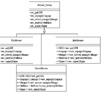
Ziadi et al. [13] modeled Core assets in terms of UML. Class diagrams are used to represent the static part and sequence diagrams to represent the behavioral part. The decision model which is a set of requirements and engineering decisions that an application engineer must resolve in order to describe and construct a product and determine the extent of variation that is possible among the systems of the domain was defined by Ziadi et al. as a class diagram (as shown in figure 1) which exposes variants as stereotyped elements. Product derivation is formalized by using a UML model
University of Nizwa, Oman December 9-11, 2014 Page 133
transformation. An algorithm is given to derive astatic model for a product and an algebraic approach is proposed to derive product-specific statecharts from the sequence diagrams of the product line. Based on product engineer’s choices, relevant classes are selected and a model transformation removes unused variants as well as optimizes the model.
3. INTEGRATE MDA AND SPL
Application engineering is the second process of SPL which comprises: (1) Application requirement engineering identifies the specific requirements for
an individual product. Then, (2) Application Design
derives an instance of the feature model, which conforms to the requirements identified in the
previous step. In parallel product-specific
requirement are captured and also modeled. (3) Application designed detailed focus on refining the design model, by considering platform specific characteristics such as programming language, middleware and component platform. Finally, (4) Application Realisation develops the final product by using the design detailed model.
The main idea is to represent all the 4 phases of application engineering by MDA model as shown in Figure 2. The requirements for the system are
modeled in a computation independent model, CIM describing the situation in which the system will be used [7]. After that, application design is transformed in a platform independent model, a PIM, is built. It describes the system, but does not show details of its use of its platform [7]. Then integrate both models into one PIM model. Application detailed design is modeled in PSM the platform specific model produced by the transformation is a model of the same system specified by the PIM; it also specifies how that system makes use of the chosen platform [7]. Finally, the PSM obtained contained all the information necessary to produce computer program code. Application Requirements Engineering Application Realisation Application Design Application Detailed Design Computational Independant Model
CIM
Platform Independant ModelPIM
Platform Specific ModelPSM
Code4. DERIVATION PROCESS
The product derivation process consists of six activities: (1) engineers starts with feature model for pre-configuration to select feature relevant to customer’s wishes. (2) Users defined in the feature instance model perform the actual configuration by taking decisions visible to them. (3) In parallel, they capture product-specific requirements in aim to do a specific-asset implementation. (4) Product integration uses generic and specific model to obtain at the end one single model. (5) Product development uses the final model to develop an
SPL MDA
Figure 1. The Abstract Factory as a decision model for the Mercure SPL
University of Nizwa, Oman December 9-11, 2014 Page 134
executable application. (6) Finally, Product testingpasses a test to the final application. Eventually, newly captured product-specific requirements are added to the product line. Figure 3 depicts the activities of our product derivation approach.
4.1 Pre-Configuration
Initially step1 uses feature models [8] as input to select the feature relevant for customer’s requirements to build the product and identify the specific-assets of the product. Once the selection is checked and validated by the engineer the output at this stage is a specialized version of feature model (instance) based on [3]. In parallel we represent this instance in MDA with CIM with UML to represent
the model but it can be represented in any form as long as the semantics of this model is well preserved.
4.2 Configuration
In this step we start with a reference configuration as input which is a partial configuration designed as basis for the development of the new product that includes all parameters setting. Reselecting or mapping of customer features according to the final instance of feature model. After that, we use the decision model as input to take decision and customize assets throw answering questions, our decisions model is based on [9]. Based on this taken decisions a configuration is generated which is also the output of this phase. The representation in MDA at this stage could be represented as PIM (Platform Independent Model).
4.3 Specific-Asset Implementation
After capturing and identifying customer's specific requirements others decision must be taken for these specific-assets. As input we used the output of the previous phase that contains taken and open decisions in order to complete those opens decisions. Based on decisions and information about their relationship with the available assets, if it's possible we just modify an already existing asset to adapt the new customer's wishes, else we develop completely a new asset from the scratch. This new developed assets must be tested individually to make sure that they work before integration. These newly developed/modified assets are the output of this phase. The representation in MDA will be also a PIM specific model to facilitate integration in a later phase.
4.4 Product Integration
In this step, we should integrate the two separated PIM specific-asset model and PIM generic model into one single PIM model in order to facilitate implementation and derivate one single coherent product that satisfy customer's requirements. After that, we use this final PIM to transform it into a PSM (Platform Specific Model) that contain all details about the final application such as component platform, a specific programming language…etc. The process of mapping PIM to PSM is automated by using a set of predefined transformation rules. The output at this stage is PSM model that represent all detailed design and includes platform decisions.
University of Nizwa, Oman December 9-11, 2014 Page 135
4.5 Product Development
Based on what we obtained from the previous phase (PSM model), we use it as an input to produce an executable application code.
4.6 Product Testing
After the product development, which is finished when we obtained the application code, this final product must pass a test before delivering to the customer. Testing means that if the integration works properly and the final product satisfies all customers' requirements, then the product is validated by the engineer. If the customer validation is failed we must repeat all the previous activities until the customer is satisfied.
5. CASE STUDY
In this section we exemplify our approach on a simplified “e-formation application” used in educational institutions. The application aim to ease and improve the teaching-learning process by means of taking advantage of internet technologies.
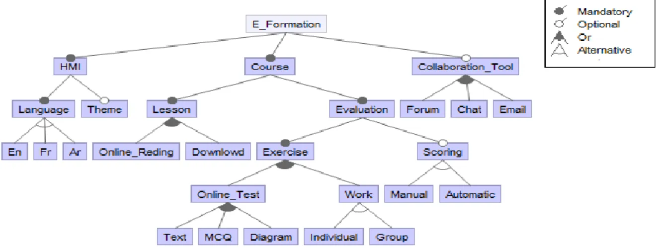
Figure 4 shows a part of the feature model we constructed for e-formation. This feature model
specifies that the e-formation application has three main features: (1) the Human Machine Interface that can supply (HMI); (2) the kind of courses that can the platform provided (Courses); and (3) the collaboration tool it uses (Collaboration tool). The HMI could contain or not Theme which is an optional feature but must contain only one of three different languages (FR, EN, and AR) since these features are mutually exclusive alternatives. Two mandatory features must be used (1) lesson which users can read the content of the lesson online (Online reading) or simply download it. (2) Evaluation the second mandatory feature of courses could be done by two different kind of Exercise (Online Test or Work).So, if we select work which is an optional feature only one of the two features must be selected (Individual or Group). Depending on the user needs, several choices are available for the type of Exercise which can be selected all of them at the same time (Text, MCQ or Diagram). Also, users can score Evaluation automatically or manually but not both since these features are mutually alternative. Moreover, Collaboration tool is an optional feature that contains three different features (Forum, Chat and Email).
In order to evaluate the described approach, we performed the case study of “e-Formation application” following the organization proposed in
section 4 in aim to create MDA models shown previously in Figure 2 (CIM, PIM, PSM and Code)
Pre-Configuration require a feature model which exposes in a concise way features and their variants
Figure4. Feature Model for e-Formation application
University of Nizwa, Oman December 9-11, 2014 Page 136
supported by SPL’s core assets. We use the featuremodel in figure 4 in aim to select the variants related to the customer’s requirements. Then, once the selection is checked we create an instance of the feature model based on [3] which can be represented in MDA as CIM. The pre-configuration step ends when the combination of the selected features is
validated. After that, the configuration phase used the output of the pre-configuration phase, during this steps decisions must be taken by the engineer. Based on this taken decisions a configuration is generated and could be represented in MDA as PIM as figure 5 shown.
Decision model rely on describing the decisions that need to be made to derive a specific product from the product line. Decisions are typically represented in form of questions with a defined set of possible answers. Decision-based variability models are often represented in tables containing decisions, their attributes, and dependencies.
Products are derived from a decision model by setting values to the decisions through answering questions and following the sequence defined by the decisions’ dependencies. Our product derivation process is also based on decisions Figure 6 shows a decision model for the e-Formation application in a
tabular notation
Name Question Range Cardinality
Online test Which type of exercise do you want to be able to use in your platform?
Text, MCQ, Diagram
1-3
Collaboration tool Which collaboration tool you want your platform has?
Forum, Chat, Email
1-3
Scoring Do you want to be able to score
student’s evaluation? Yes,no 1
Figure5. Class Diagram for e-Formation application
University of Nizwa, Oman December 9-11, 2014
Page 137
In parallel, specific-requirements are captured to bedesigned and integrated later. The model design of specific-requirements is represented as a PIM model. Application specific PIM is identical to the generic PIM except the content of PIM is only relevant to a specific application. After implementing two separate models (generic and specific) product integration phase integrates those two models into one single model which will still be a conventional PIM. Next, the obtained model after integration is detailed in order to map PIM to PSM that contain specific characteristics such as programming language, middleware and component platform. Finally, product realisation takes PSM to produce an executable application.
6. CONCLUSION
In this paper we have proposed a product derivation process using MDA approach. MDA with its organized layers of models achieving the SPL goals with more benefits and the generative natures of MDA makes it a useful approach to derive product for SPL .MDA consists in the separation of platform dependent and platform independent models, which distinct between business (CIM), applications (PIM), and technology (PSM). The main idea is to represent each phase of the application engineering (application requirement engineering, application design, application detailed design, and application realisation) by MDA models. The derivation process proposed consists of six activities, each activities output was represented by MDA. We also illustrated each step of the process with an e-Formation application.
As future work, we will add more features and also intend to build a set of components to this e-Formation application.
At the tool level, improvements may concern the visual representation of feature models (via the Ecore reflexive editor provided by Eclipse). A possibility is to develop our metamodel and generate this later using tool such as GMF (http://www.eclipse.org/gmf/).
7.
REFERENCES
[1] Clements,P., Northrop,L. Software Product Lines: Practices and Patterns. The SEI series in
software engineering. Addison-Wesley, Boston, 2002.
[2] Czarnecki, K., Helsen, S.: “Feature-Based Survey of Model Transformation Approaches”, IBM Systems Journal, 45, 3, 621-64, 2006. [3] Czarnecki, K., Helsen, S., Eisenecker, U.:
“Staged Configuration Using Feature Models”. In Proceedings of the 3rd Software Product-Line Conference (SPLC’04), September 2004. [4] Deelstra, S., M. Sinnema, and J. Bosch, Product
Derivation in Software Product Families: A Case Study. Journal of Systems and Software, 2005. 74(2): p. 173-194.
[5] Guelfi, N. and Perrouin, G., A Flexible Requirements Analysis Approach for Software Product Lines, I Requirements Engineering: Foundation for Software Quality. 2007, Springer Berlin / Heidelberg. p. 78-92.
[6] Hotz, L., A. Gunter, and T. Krebs, A Knowledge-based Product Derivation Process and some Ideas how to Integrate Product Development, in Proc. of Software Variability Management Workshop. 2003: Groningen, The Netherlands.
[7] J. Mukerji, and J. Miller, "MDA Guide," 2003. [8] Kang, K., Cohen, S., Hess, J., Novak, W.,
Peterson, A.: “Feature-oriented domain analysis (FODA) feasibility study”, Technical Report CMU/SEI-90-TR-021, SEI, Pittsburgh, PA, November 1990.
[9] K. Schmid and I. John. A Customizable
Approach to Full-Life Cycle Variability Management. Journal of the Science of
Computer Programming, Special Issue on Variability Management, 53(3), pp. 259-284. 2004.
[10] Ø.Haugen, B. Møller-Pedersen, J. Oldevik, and A. Solberg. An MDA-based Framework for Model-Driven Product Derivation. In SEA, pages 709–714. ACTA Press, 2004.
[11] Perrouin, G., Klein, J., Guelfi, N., and Jezequel, J.M. Reconciling Automation and Flexibility in Product Derivation. in 12th International
Software Product Line Conference (SPLC).
2008.
[12] S. D. Kim, H. G. Min, J. S. Her, and S. H. Chang. DREAM: A Practical Product Line Engineering Using Model Driven Architecture. In Information Technology and Applications. (ICITA), pages 70–75, Washington, DC, USA, 2005.
[13] T. Ziadi and J.-M. J´ez´equel. Product Line Engineering with the UML: Deriving Products. In Families Research Book. Springer, 2006.