A 1-mW Vibration Energy Harvesting System for
Moth Flight-Control Applications
by
Samuel C. Chang
MASSACHUSETrS INSM1E OF TECHNOLOGYFEB 2
3
2010
LIBRARIES
Submitted to the Department of Electrical Engineering and Computer
Science
in partial fulfillment of the requirements for the degree of
Master of Science in Electrical Engineering and Computer Science
at the
MASSACHUSETTS INSTITUTE OF TECHNOLOGY
February 2010
@
Massachusetts Institute of Technology 2010. All rights reserved.
Author..
... 1 .. .. . . .... .Department of Electrical En
ng and Computer Science
December 28, 2009
Certified by
... ... . .. ...Jeffrey H. Lang
Professor of Electrical Engineering and Computer Science
Thesis Supervisor
--- 7
A ccepted by ...
...
Terry P. Orlando
Chairman, Department Committee on Graduate Students
A 1-mW Vibration Energy Harvesting System for Moth
Flight-Control Applications
by
Samuel C. Chang
Submitted to the Department of Electrical Engineering and Computer Science
on December 28, 2009, in partial fulfillment of the
requirements for the degree of
Master of Science in Electrical Engineering and Computer Science
Abstract
This thesis focuses on the approach and methodologies required to build a 1-mW
energy-harvesting system for moth flight control applications. The crepuscular hawk
moth Manduca sexta is the chosen test subject. This project is part of the Hybrid
Insect MEMS (HI-MEMS) program. The objective of the program is to establish an
interface between adult insect neural systems, wireless communication and MEMS
systems so that insects may be directed to fly to specific locations in real time.
As in all micro-air vehicles, power is one of the major concerns. A power source
on the moth is required to support the flight control and wireless communication
systems. There are two methods by which these payloads might be powered. The
first method is to draw power from a battery, while the second method is to harvest
energy from the environment. Batteries have the advantage of simplicity, while energy
harvesting systems have much longer life and lower mass per total energy delivered.
In addition, the total mass of circuitry, MEMS devices, and batteries may severely
limit flight duration. Therefore, we have chosen the energy-harvesting method.
The energy harvesting system includes a vibration energy harvester and a boost
converter that delivers power at the required 1-V level for the entire flight control
system. The latest harvester has a mass of 1.28 g and output power of 1.7 mW into
a matched resistive load when the moth vibrates with a +0.37-mm amplitude at 25.8
Hz, resulting in a ±7.82-mm harvester amplitude.
A 2-stage AC-DC boost converter with off chip inductors has been designed and
fabricated in 0.18 um CMOS technology. SPICE simulation and experiments using
equivalent discrete components prove that the converter can achieve 71.68% efficiency.
The test experiment of the chip will be conducted later this winter and is not included
in the scope of this thesis.
Thesis Supervisor: Jeffrey H. Lang
Acknowledgments
This thesis was supported by the Air Force Research Laboratory as part of the DARPA HI-MEMS Program under Contract FA8650-07-C-7704. National Semicon-ductor Corporation provided the free chip fabrication discussed in Chapter 3. I was personally supported by a Presidential Graduate Fellowship provided by MIT. In addition, I would like to thank the Daniel Lab at the University Washington for charactarizing the body vibration of the moth and testing numorous resonators and harvesters for us. The Voldman lab at MIT and Alice Stone from the University of Arizona also helped us connect the harvester to the moth. Without their knowledge of the moth and generously providing their flight test facilities, this work would be impossible.
The iterations and construction of the harvester occured with plenty of guid-ance and support from Dave Otten, Frank Yaul, Francis O'Sullivan and Alejandro Dominguez-Garcia. I especially want to thank Dave for laying out the Flexible PCB, building the harvesters and implementing the discrete power electronics. I'd also want to thank Frank Yaul, the best UROP ever, for designing the ABS plastic springs such that the harvester really became flyable. Without Dave and Frank, our harvester would still be in the stone age and would have never been able to achieve the mile-stones.
I also want to extend a warm thank you to Professor Anantha Chandrakasan, Professor David Perreault and Professor Alex Slocum. Thank you all for spending time in giving me valuable insight into the lower power circuit, power electronics and mechanical harvester design.
I owe a huge intellectual debt to numerous individuals working at the Laboratory for Electronic and Electromagnetic Systems for their help during the development of this thesis. I would especially like to thank David Giuliano for generously helping me out with the Cadence simulations and inductor designs. Thanks Giuliano! Wei Li, Jiankang Wang, Jackie Hu, Anthony Sagneri, Yehui Han, George Hwang, Uzoma Orgi, Kevin Brokish, Robert Pilawa, Riccardo Signorelli and Warit Wichakool helped
me ease the transition into LEES early on and provided unwavering support whenever I ran into difficulties. Above all, making LEES a fun place to work.
Without my buddies at MIT, life would be completely different. Thank you Albert for being like a brother to me and giving me honest advices which really helped me become a better person. Thank you Wilt and Heechul for both being awesome roommates, great listeners and supporting me when I needed you guys the most. I would also like to thank Patrick Lin from BU fellowship for being my mentor and opening your home to me. Thank you Patrick! Last, I would like to thank Jingjing for being there for me and being ultra-supportive throughout the writing of this thesis. Thank you dear.
My parents, Peter and Carol Chang, provided much guidance and moral support during my educational career and allowed me to reach where I am today. Their care and understanding go way beyond the norm, and I am forever grateful. Your prayers gave me strength and helped me overcome all the challenges at school and in life. This thesis belongs to them as much as it does to me.
Professor Jeffrey Lang deserves my deepest gratitude. Throughout this research, he provided countless suggestions for overcoming difficult theoretical and experimen-tal barriers. Without these critical insights, this thesis would not exist. I will never forget all the time he spent with me both during and after research meetings, even when he already had many other businesses to attend to. Furthermore, he never hesitated to remind me to rest when I had exams in the courses I was taking. Thank you so much for being patient when progresses were slow and above all, for being a great role model for me in research and in life. I cannot possibly repay all your kindness and care. Thank you Professor Lang.
Last, I would like to thank God for everything. If it was not the miracle that gave me birth and the protection and guidance throughout my life, I would not have any of these things in my life. Thank you Lord.
Contents
1 Introduction 15
1.1 Background . . . . 15
1.2 Harvester System Outline . . . . 16
1.2.1 Resonant Geneator . . . . 17
1.2.2 AC/DC Boost Converter . . . . 19
1.2.3 Experimental Results . . . . 19
1.3 Previous Research. . . . . 20
1.3.1 Vibration Energy Harvesting . . . . 20
1.3.2 Insect Energy Harvesting . . . . 22
1.4 Chapter Summary . . . . 23
2 Vibration Energy Harvester 25 2.1 Constraints . . . . 25
2.1.1 Payload Mass and Volume Constraint . . . . 26
2.1.2 Moth Vibration Characterization . . . . 26
2.2 Harvesting Strategy . . . . 28 2.3 Resonant Generator . . . . 30 2.3.1 Overview . . . . 30 2.3.2 Spring-mass-damper Model . . . . 36 2.3.3 Electromagnetic Analysis . . . . 39 2.3.4 Simulation . . . . 42 2.3.5 Final Design . . . . 45 2.4 Experiments . . . . 46 7
2.4.1 Harvester Voltage Measurement . . . . 2.4.2 Harvester Optimal Load Experiment . . . . 2.5 Chapter Summary . . . .
3 Power Electronics
3.1 System Overview . . . . 3.1.1 Design Constraints . . . . . 3.1.2 Two-stage Boost Converter 3.2 Two-stage Boost Converter Design 3.2.1 Boost Converter Concept . 3.2.2 Optimization . . . . 3.2.3 Chip Layout . . . . 3.3 Inductor Design . . . .
3.4 Discrete Circuit Verification . . . .
3.5 Chapter Summary . . . .
4 Summary, Conclusion, and Future Work
4.1 Sum m ary . . . . 4.2 Conclusions . . . . 4.3 Future Improvements . . . . 4.4 Final W ords . . . .
A MATLAB Codes
A.1 Harvester Optimization . . . . A.2 Two Stage Tapped Inductor Boost Converter Optimization . . . . A.3 Inductor Optimization . . . .
51
. . . . 52 . . . . 52 . . . . 54 . . . . 55 . . . . 55 . . . . 57 . . . . 59 . . . . 61 . . . . 65 . . . . 67 71 71 73 73 7577
77 84 88List of Figures
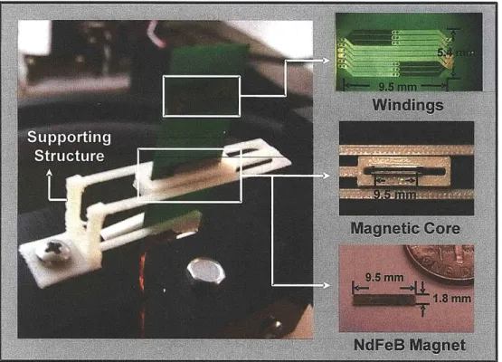
1-1 System Overview . . . . 17 1-2 Resonant generator parts. The supporting structure made from ABS
plastic was designed and fabricated by Frank Yaul. . . . . 18
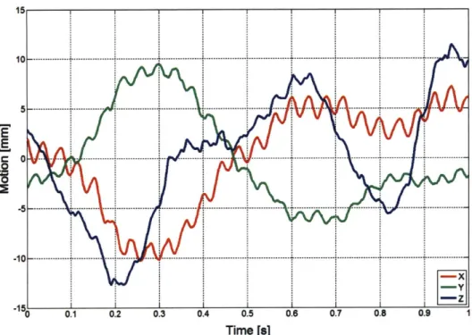
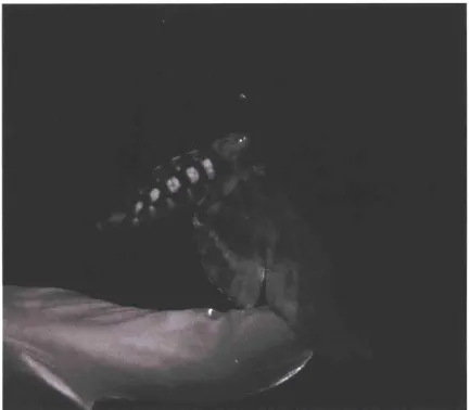
2-1 Moth dorsal thorax design space constraint . . . . 26 2-2 Moth flight motion characterization . . . . 27 2-3 Snapshots of the moth flying and flapping its wings with the resonator
attached to its dorsal thorax. This demonstrates that the moth can and will fly with the resonator. . . . . 31 2-4 ABS plastic harvester fully assembled with the magnetic core and
flex-ible printed circuit board. The ABS components were designed and fabricated by Frank Yaul, an undergraduate in the Lang Lab at MIT. 32 2-5 Configuration of the multi-pole flexible printed circuit board. . . . . . 34 2-6 Flexible printed circuit board under microscope. The winding layout
was drawn by David Otten, a research scientist in the Lang Lab, and manufactured by Altaflex. . . . . 35 2-7 The resonant converter modeled as a spring-mass-damper system. . . 36 2-8 The springboard and sandwich magnetics designs that were studied
as part of the design process for the energy harvester. In these two designs, the windings move into and out of the page. . . . . 40
2-9 Illustration of a six pole sandwich type magnetics design in the CMP user interface. These magnets each have a magnetic flux density of 1.5 T. Their magnetic flux is in the z-direction and the magnetization reverses from magnet to magnet in the y-direction of travel to form a six-pole magnetic structure. Our final two designs were three-pole and four-pole magnetic structures. . . . . 41 2-10 Harvester optimal design curve. Designs in the red box are magnified
in (b) and its detailed designs specifications are shown in Table 2.3. . 44 2-11 Harvester vibrating on shaker table . . . . 46 2-12 Loaded harvester 3-phase voltage waveforms compared with MATLAB
sim ulation results . . . . 47 2-13 Output power versus load resistance tradeoff. Simulation and
exper-iment are matched nicely with maximum output power happening at 450 milli-ohm load resistance. . . . . 48 3-1 System overview of the two-stage boost converter. . . . . 54 3-2 Boost converter circuit. . . . . 56 3-3 Inductor currents in the first and second stage of the boost converter.
Operating conditions and expected performances of the two boost con-verters are shown in Table 3.1. . . . . 58 3-4 Power transistor chip layout in CMOS 0.18 um process. The size of
the chip is 3 mm x 3mm while the bare die mass is 0.0126 g if assuming the chip thickness to be 600 tm. . . . . 60 3-5 Inductor size and operation frequency effect on one phase of the
first-stage boost converter output power and efficiency. . . . . 62 3-6 Power loss versus physical mass tradeoff of a 10 tH inductor operating
at Idc = 65 mA and f = 100 kHz. . . . . 64 3-7 Discrete 2-stage boost converter. This circuit was built by Dave Otten
and verified that our 2-stage boost converter topology works. . . . . . 66 3-8 First stage boost conveter model . . . . 67
3-9 Comparison between experimental and simulation output power of first stage boost converter . . . . 68
List of Tables
2.1 Altaflex flexible printed circuit board process capabilities and tolerances. 35 2.2 Average magnetic flux density table for different magnetic core
geome-tries. The average magnetic flux densities were measured in the middle of the air gap where the coils will be placed. Each magnet has a mag-netic strength of 1.5 T. MT, MW and PP are respectively the magnet thickness in the direction of the magnetic flux, the magnet width and the magnetic core plate-to-plate distance. . . . . 42 2.3 Harvester optimal design table with magnet and winding design details.
The two designs at the top of the table were chosen as they generate the maximum power and satisfy the mass constraint. . . . . 44 3.1 2-stage boost converter design parameters. . . . . 59 3.2 Optimal design parameters of a 10 pH inductor with a mass near 0.1 g. 64 3.3 Discrete switch model parameters. . . . . 67
Chapter 1
Introduction
1.1
Background
The research conducted within the scope of this thesis is part of the Hybrid Insect MEMS (HI-MEMS) program supported by the Defense Advanced Research Projects Agency (DARPA)1. The objective of the program is to develop and demonstrate self-contained mobile on-insect electronics through which the motion of the insect can be controlled remotely. Thus, the electronics receive motion commands wirelessly and issue motion commands to the insect via electronic connections made to its nervous system. The on-insect electronics require a power source and it is the objective of this thesis to develop and demonstrate that power source.
DARPA and other research institutes have been interested in micro-vehicle related research since the early 1990's. One example of their interest is the Nano Air Vehicle (NAV) program2, the goal of which was to miniaturize man-made flying vehicles to
a sub-10-cm size. While such vehicles would undoubtedly have impact, severe power constraints drastically limit their mission time (-20 min), while the nature of the vehicles makes them unsuitable for unobtrusive indoor missions. The most efficient small flying machines are arguably the flying insects, which can fly for days-to-weeks at a time. In the late 1990's, the DARPA Defense Sciences Office (DSO) sought to
lwww.darpa.mil/MTO/Programs/himems/index.html
take advantage of insects through the Controlled Biological Systems program, the goal of which was to use insects and other small animals to collect information, for example by training them to seek out useful targets or tapping into their sensory nervous systems to monitor sensory information.
Given developments in insect neurobiology and the evolution of Microelectrome-chanical systems (MEMS), a new interdisciplinary approach has surfaced for achieving the desired mission capability. MEMS, which are small, light and low-power, and have a diverse set of electrical and mechanical capabilities, are the ideal man-made systems for instrumenting an insect. Insects on the other hand, have biological advantages including energy storage, efficient flight control and highly adapted sensing compared to artificial micro-vehicles. The Hybrid Insect MEMS (HI-MEMS) program, spon-sored by DARPA, takes the advantage of both worlds and focuses on creating a robust long-term flight-control nano air vehicle. The crepuscular hawk moth Manduca Sexta was chosen to be the test platform by our team, which consists of researchers from MIT, the University of Washington and the University of Arizona.
As with all untethered micro-vehicles, on-board power is a major challenge. Solu-tions include long lifetime batteries, renewable energy sources, energy harvesting, etc. The goal of this thesis is to meet the energy challenge through the development of a vibration energy harvesting system capable of providing 1 mW of electrical power to the entire flight control system.
1.2
Harvester System Outline
As shown in Figure 1-1, the energy harvesting system consists of four major compo-nents: the moth body vibration, the vibration energy harvester (resonant generator), the AC-DC boost converter and the flight control battery. The moth body vibrates at a frequency of 25 Hz and amplitude of ± 1 mm in response to wing flapping. Its body vibration provides the energy scavenging source for our system. The second component is a vibration energy harvester that is a linear AC poly-phase permanent-magnet synchronous generator. This generator is supported by a resonant spring
1-VZinc
Hearing
Aid
Battery
Figure 1-1: System Overview
mass structure that enhances the moth wing-flapping vibrations; the generator mag-nets and cores serve as the resonating mass. The third component is an AC/DC boost converter. It comprises power electronics that rectify and boost the output from the generator to charge a
1-V
battery. Finally, the battery stores the harvested energy and acts as a energy source for the flight control, radio devices and the power electronics. Since the moth vibration is constrained by its own physical limitations, and the battery will be implemented by using commercially available components, the focus of this thesis is on the resonant generator and the boost converter. Design details and challenges of the two stages are given in the following subsections. At the end of this section, an overview of the results of this thesis is also given.1.2.1
Resonant Geneator
The resonant generator comprises a support structure, moving magnets and core, and stationary windings. These parts are shown in Figure 1-2. The first three components form a spring-mass resonator tuned to the wing-flapping frequency of the moth; the structure is the spring, and the magnets and core provide the dominant proof mass.
Figure 1-2: Resonant generator parts. The supporting structure made from ABS plastic was designed and fabricated by Frank Yaul.
The magnets, core and windings form the linear 3-phase AC generator.
When the moth is flying, the thorax vibration of the moth will excite the res-onator which supports permanent magnets. The permanent magnets are aligned with the windings such that as the resonator vibrates, the flux through the windings varies, inducing a voltage across the windings in accordance to Faraday's law. The energy introduced mechanically into the resonator by the vibration can be extracted electronically through the electromagnetic generator.
There are several major challenges to building a resonant generator on a flying insect. The first is the harvester mass and volume limitations due to the moth's physical constraints. A typical Menduca Sexta has a payload capacity around 0.6
-1.0 g, and a dorsal tent-shaped payload volume approximately 8 mm wide and 15 mm tall beneath the wings at their apex. The second challenge is the low frequency
(25 Hz), low amplitude (t1 mm) and narrow bandwidth vibration characteristic. Finally, more than 1 mW of power must be generated such that the flight control
and radio devices have sufficient operating power. In conclusion, the power density of this resonant generator must be higher than 1.67 W/kg at 25 Hz.
1.2.2
AC/DC Boost Converter
As shown in Figure 1-1, the AC-DC boost converter operates to extract maximum power from the generator, and deliver that power to a 1-VDC battery, through two stages. The first stage is a combined AC/DC rectifier and DC/DC boost converter. There is one such stage for each generator phase, and the outputs of these parallel stages deliver energy to a common intermediate energy storage capacitor at about 50 mV. Following the capacitor is a single DC/DC boost converter that raises the voltage from 50 mV to 1 V.
The two major challenges for designing the power electronics are the output char-acteristics of the resonant generator and the mass and volume limitations of the moth. Each winding of the resonant generator has an AC output voltage with a RMS level of 14 mV and output resistance of 0.1 Q. This means that the power electronics must provide a high voltage conversion ratio and an extremely low input resistance. On the other hand, the physical limitations of the moth, as mentioned in Section 1.2.1, limits the use of certain topologies which use heavy inductors. This thesis will pro-vide insight into the design, optimization, and experimentation of a high efficiency AC/DC boost converter for moth flight control applications.
1.2.3
Experimental Results
The resonant generator is capable of generating 1.7 mW of power at 25 Hz into a resistive load. The generator has a mass of 1.28 g and has been tested on a shaker table that simulates the vibration frequency and amplitude of the moth body vibration. Experimental details and a matching between the experimental results and the design model developed here is given in Section 2.4.1.
With 1.4 mW of input power from the resonant generator, the AC/DC boost converter is capable of delivering 1.059 mW of power into the load with 71.68%
efficiency. This converter was implemented with discrete components to demonstrate the validity of the topology. An integrated version of the circuit with power MOSFETs and rectification functions has been fabricated in 0.18 pm CMOS technology and waiting to be tested. Its efficiency is expected to be near 80%. Wiring losses and switching losses can be further eliminated in the integrated circuit and hence giving us a good chance of delivering more power at a higher efficiency.
With the target power delivered, the immediate future work would be reducing the system mass to below 1 g. This seems promising by means of trimming down our current structure or changing to a new structural material such as carbon fiber.
1.3
Previous Research
A careful literature survey of recent developments in the field of energy harvesting is appropriate for placing the current thesis in context. However, due to the wide range of techniques used for energy harvesting, such as exploiting chemical and thermal gradients, this thesis will limit the survey to vibration energy harvesting and insect energy harvesting.
1.3.1
Vibration Energy Harvesting
Vibration energy harvesting involves the creation of some physical structure that can couple in kinetic energy from small vibrations and convert it into storable electric energy. Due to the growing demand of autonomous sensors that must function with-out the need for human intervention, interest in this topic has burgeoned in recent years. Applications on the market today include shaker flashlights, ocean wave en-ergy harvesting buoys3, wireless sensor node energy harvesters4, etc. Despite all these different applications for vibration energy harvesting, three main strategies of conver-sion dominate: piezoelectric, capacitive-based electric, and permanent-magnet-based magnetic.
3www.technologyreview.com/Energy/19295/?a=f 4
Review papers by Roundy [1] and Mitcheson [2] have compared these three topolo-gies and shown that although current harvester designs are still operating well below their maximum power, there has been a significant improvement with time. One of the index to evaluate the performance of a harvester is the normalized power
Pn = P/PMAX [2]. It measures how close the performance of a specific device comes
to the optimum level. Both frequency and the mass of the proof-mass are normalized in the calculation. From the data in [2] and the latest harvesters reported at Power-MEMS 2009, all harvesters have a P, smaller than 0.2 while the harvester reported in this thesis has a P,,= 0.36 at 25 Hz.
Numerous research groups have focused on piezoelectric energy harvesting [3, 4, 5] due to its potential of achieving the highest converted power per unit volume. Piezoelectric materials, such as quartz and barium titanate, contain permanently polarized structures that produce an electric field when the materials deform as a result of an imposed mechanical strain. Kymissis et al employed unimorph strip made from piezoceramic composite material and a stave made from a multilayer laminate of PVDF foil inside sport sneakers to harvest the parasitic kinetic energy generated during walking [3]. An input signal of 1 Hz, similar in frequency to a person walking briskly, produced 20 mW peak power for the PVDF and 80 mW for the unimorph; this translates to roughly 1-2 mJ per step.
Electric energy harvesting couples vibration energy into the system by having it perform work on charges via the electric field between parallel plate capacitors [6]. In a typical scenario, charges are injected onto capacitor plates when they are closest together, meaning that the capacitance is at its maximum. Because charges of opposite polarity reside on the separate plates, the plates are attached to each other. Therefore, as vibration energy separates the two plates, it performs positive work on the charges, which are then drained from the plates when the capacitor voltage is highest, and harvested using power electronics. Besides the variable capacitor, one can also employ a layer of embedded charge, or electret, in the dielectric to carry out electric energy harvesting [7]. Such a distribution of permanent charges induces a voltage on the capacitor plates, polarizing them. As external vibration moves the
capacitor plates and alters the capacitance, charge transport along the plates delivers power to the load.
Finally, magnetic energy harvesting seeks to convert vibrational kinetic energy into an induced voltage across coils of wire, which then can deliver power to an appropriate load. This is typically done by attaching either a permanent magnet, such as that made from Neodymium Iron Boron, or a coil of wire onto a cantilever beam that is vibrationally actuated [8, 9]; the other one remains fixed. In either scenario, the coil will cut through magnetic flux as the cantilever beam vibrates, creating an induced voltage in accordance with Faraday's law.
As discussed further in Section 2.2, the magnetic vibration energy harvesting ap-proach was chosen for our application due to the low frequency and narrow bandwidth vibration characteristics of the moth shown in Figure 2-2. On the one hand, the 25 Hz vibration frequency of the moth is too low for both variable capacitors and piezo-electrics. On the other hand, the narrow bandwidth vibration argues for a resonant harvester employing a spring and proof mass to enhance the vibration stroke, which is perfect for the magnetic harvesting approach. Detailed reasonings of the harvesting method decision are given in Section 2.2.
1.3.2
Insect Energy Harvesting
Possible alternative energy sources on the insect include thermal gradient, light, or chemical energy stored within the moth. Previous work on insect energy harvesting has compared these harvesting concepts for moths [10], studied piezoelectric-based vibration harvesters for moths [11], and demonstrated 10 jtW/cm2 thermoelectric harvesting from beetles [12]. However, to this date, none of the vibration energy harvesting methods have reported experimental data and the thermoelectric harvester generates 0.8 pW, more than 1000 times smaller than our latest output power of 1 mW.
1.4
Chapter Summary
This chapter served both as an introduction to the world of energy harvesting as well as motivation for the rest of this thesis. As noted, numerous techniques exist for harvesting energy from the environment that otherwise would have been lost. Potential energy sources include solar power, thermal and chemical gradients, acoustic noise, and vibration. Vibration energy harvesting be further divided into piezoelectric, magnetic, and electric, determined by how vibration energy is coupled into the system. This thesis presents a road map for creating a magnetic vibration energy har-vester for mass-limited 1-mW applications. The road map is divided into different sections, including electromechanical analysis, harvester design and power electronics design. For each section, an analysis shows the elements of importance in the design of a complete harvester. These analyses are connected to each other, providing a complete road map for the design of energy harvesters. Furthermore, the analyses show technology challenges where more research can improve the performance of the harvesters.
Chapter 2 gives an in-depth discussion of the simulation, optimization and experi-mentations of the vibration energy harvester. Through three generations of iterations, our latest harvester built with ABS plastic weighs 1.28 g and generates 1.7 mW of power into a resistive load. Additional survey of possible ambient energy sources in the system environment, and different vibration energy harvesting methods are also discussed. Chapter 3 outlines the design, simulation and experimentation of the power electronics which performs the harvester to battery voltage conversion. Finally, Chapter 4 summarizes the thesis and its conclusions, and presents possible direction of future work in this area of research.
Chapter 2
Vibration Energy Harvester
This Chapter presents the design, fabrication, and testing of a harvester that trans-duces the mechanical wing-flapping vibration energy from the moth into electrical energy. The target moth, Manduca Sexta, has a payload capacity near 1 g, and a tent-shaped dorsal payload volume approximately 8 mm wide and 15 mm tall. In addition, it's body vibrates at 25 Hz with an amplitude of +1 mm. Operating within these constraints, the energy harvester is designed to deliver 1 mW of electrical power at 1 VDC such that the flight control and radio system can operate properly. Based on the vibration characteristics, a magnetic induction harvesting strategy driven by permanent magnets moving past windings is chosen. A thorough electromagnetic and mechanical analysis of the harvester is developed here to provide a accurate model for optimization of the harvester. Finally, a table of harvester designs that can generate 1-mW of power and satisfy all the design constraints is generated. This table includes specific dimensions, configuration, output power and mass of the harvester design. At the end of this chapter, an optimal design is chosen, fabricated and tested.
2.1
Constraints
The design constraints of our vibration energy harvester come from the physical limitations of the Menduca Sexta. In this section, we first investigate the load carrying capability of the moth. This ultimately determines the upper-bound of the volume
(a) Front view of volume design constraint. (b) Side view of volume design constraint.
Figure 2-1: Moth dorsal thorax design space constraint
and mass of our harvester. In addition, we need the vibration source characteristics to determine a suitable harvesting method. A thorough analysis on the moth vibration
frequency, amplitude and bandwidth is given in the second part of this section.
2.1.1
Payload Mass and Volume Constraint
The payload capacity of Manduca Sexta on its dorsal thorax is around 0.6 - 1.0 g. The mass of the harvester should be less to accomodate additional payloads, some to be powered by the harvester. The dorsal payload volume is tent shaped and is shown in Figure 2-1. It has a 6-8 mm base, and a 10-15 mm height beneath the wings when they close at the apex of their flapping motion. The length of this volume can be 4-5 cm so long as the harvester mass distribution does not affect the flight balance of the moth.
2.1.2
Moth Vibration Characterization
The characterization of the vibration source is essential in deciding which harvesting method to implement and in determining the output power limits. For our vibration harvesting system, the source is the thorax movement of Menduca Sexta during flight.
10 - - --- + -- - - -... ... --- -- --- + - - - -- -- - - ... ... - ---- --- - - -5 . . . . . . . . . .. . . .
-
-vvv
--10 ---- - - - - ---- --.-- t -. .... . ..-. .. .... ... ... .. ..- . . . ...-.. . ...-. . ....-. ... ..-. ....- .. ... .- . ... . . -. -- X -z 0 0.1 0.2 0 3 0.4 0.5 0.6 0.7 0.8 0.9 1 Time [s]
(a) Three dimensional moth movement provided by the Daniel Lab at UW.
7 6 -5 E .-.4 . 0
tracked by high speed video camera. Raw data
ide=11456mm
50 60 70 80 90 10
Frequency [Hz]
(b) Fourier Transform of moth motion shows that the moth thorax vibrates at 25 Hz with an amplitude of 1.1458 mm.
Figure 2-2: Moth flight motion characterization
... ... ... . ... I k
- --- - . ..- .. - .. ... . .. ..-. - .. .. . .. ..
E-E :E
Using high-speed video cameras, colleagues from the Daniel Lab at UW tracked the three-dimensional inertial motion of a moth during flight. A graph of the three
dimensional movement is shown in Figure 2-2(a).
The vibration characteristic in which we are interested is its amplitude and fre-quency. This is seen in the Fourier transform of the three dimensional inertial move-ment of the moth. As shown in Figure 2-2(b), the moth thorax vibration has an amplitude of 1.1258 mm and frequency of 25 Hz normal to the dorsal side of the thorax. It can also be seen from Figure 2-2(b) that the vibration frequency has a relatively narrow bandwidth. These vibration characteristics were observed from one moth, but additional experiments indicate that there is little variation from moth to moth. According to these vibration characteristics and physical limitations of the moth, we will explore various harvesting strategies in the following section and determine one that would acheive our goals.
2.2
Harvesting Strategy
MEMS vibration energy harvesters have employed a number of different approaches to transduce mechanical energy into electrical energy for end use. These methods include variable capacitors, piezoelectric, variable inductors, permanent electric and permanent magnet. These strategies have their own merits for vibration sources of different frequency, amplitude and physical design space limitations. As shown in Figure 2-2, our vibration source is the low frequency, low amplitude and narrow bandwidth thorax wing-beat vibration of the insect while flying. In addition, the payload has volume and mass limitations of approximately 2.4 cm3 and 0.6 g.
First, let us consider variable capacitors. In order to generate 1 mW of power at 25 Hz, the harvester has to generate 40 pJ/cycle. Taking into account the energy stored in the capacitor (leoE2) and the electric field limit of 106 V/m, the capacitor would
have to store 4.4 J/m3. By dividing the required energy per cycle by the maximum energy density density, the minimum required air-gap volume for the variable capac-itor harvester is determined to be approximately 9.1 cm3, nearly 4 times larger than
the payload volume limit of the moth. Therefore, the variable capacitor harvesting method is not feasible.
Next, let's investigate the piezoelectric harvesting approach. The kinetic force on the piezoelectric material can be expressed as MAw2, where M is the mass of the
proof mass, A is the vibration amplitude of the piezoelectric material and w is the vibration angular frequency. Considering the payload mass and volume shape limit, we can assume the proof mass to be 0.1 g with a vibration amplitude of 5 mm. The vibration angular frequency is determined by the moth's vibration frequency of 25 Hz. The maximum kinetic force on the piezoelectric material is therefore 12 mN and the output voltage can be calculated using the following equation:
Vat =
g
3 3 xF
xT/S
(2.1)
where g33 is the piezoelectric constant, F is the kinetic force, T is the thickness of
the material and S is the cross sectional area of the material. If we substitute the piezoelectric constant of 0.02 Vm/N and assume the material thickness to be 0.1 mm and cross sectional area to be 3 mm2, we can obtain the output voltage. The output voltage is 3 mV which is too small for power electronics to convert to 1 V. Therefore, the piezoelectric method cannot be implemented here due to the low frequency of the wing beat which results in a low output voltage.
Finally, let us consider variable inductors and permanent electrets. The variable inductor method generally requires too much stationary mass, hence decreasing the allowable proof mass. A lower proof mass would then greatly limit the output power. In addition, it is more complex and lossy than systems with permanent magnets, particularly at small size scales. As for permanent electrets, they have a very low energy density and poor stability in comparison to permanent magnets.
The only remaining approach is the permanent magnet topology. Additionally, the narrow bandwidth of the moth vibrations, as shown in Figure 2-2, argues for a resonant harvester employing a spring and proof mass to enhance the vibration stroke. A stroke of about t 8 mm is allowed beneath the wings at the top of their motion.
To achieve a 1-mW power output then requires the conversion of 40 mJ during each cycle with a peak force of 2.5 mN, assuming 100% energy-conversion efficiency from the generator and its attendant power electronics. This is again incompatible with small low-mass, low voltage capacitive or piezoelectric energy conversion, and so a magnetic-based harvester is selected here.
2.3
Resonant Generator
2.3.1
Overview
The resonant generator comprises a plastic spring, moving magnets, an iron core, and stationary windings. The first three components form a spring-mass resonator which is tuned to the wing-flapping frequency of the moth of 25 Hz. In the spring-mass resonator, the magnets and core provide the dominant proof mass. The magnets, core and windings form the linear poly-phase AC generator.
One of the earliest concerns of our approach was whether or not the moth would fly with a resonator on its dorsal thorax. Figure 2-3(a), shows a snap-shot of the moth carrying a resonator during flight. It clearly demonstrates that a moth can and will fly while carrying a resonant energy harvester. This is an important proof that our approach to designing the energy harvester is possible and reasonable. Figure 2-3(b) is one frame from a movie which shows our latest ABS plastic resonator attached to the moth. The movie demonstrates that wing flapping is unaffected by the resonator, even when the resonator is elevated on a pedestal. The blurred motion of the moving mass is visible at the top of the photograph.
In the following parts of this section, we will give an overview of the mechanics of each component in the resonant generator in order to aid the understanding of the vibration energy harvester.
(a) Moth taking off of the researchers thumb while flying with a res-onating spring attached to its dorsal thorax. This resonator was imple-mented by Dr. Alejandro Dominguez-Garcia, a post-doc in the Lang Lab at MIT.
(b) Moth flapping its wings with plastic resonant generator attached to its dorsal thorax. This moth took off with the resonator afterwards and was never recovered. The experiment was conducted by Wei Mong Tsang from the Voldman Lab at MIT.
Figure 2-3: Snapshots of the moth flying and flapping its wings with the resonator attached to its dorsal thorax. This demonstrates that the moth can and will fly with the resonator.
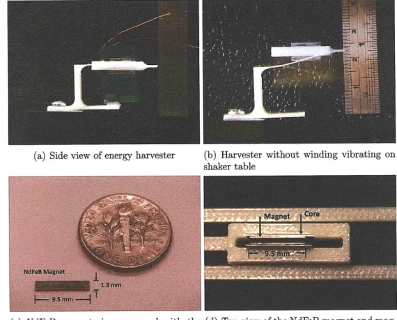
(a) Side view of energy harvester (b) Harvester without winding vibrating on shaker table
(c) NdFeB magnet size compared with the (d) Top view of the NdFeB magnet and
mag-dime. netic core inside the ABS plastic spring.
Figure 2-4: ABS plastic harvester fully assembled with the magnetic core and flexible printed circuit board. The ABS components were designed and fabricated by Frank Yaul, an undergraduate in the Lang Lab at MIT.
Spring
The spring is folded to be compact, and carry the magnets and cores level as they sweep vertically past the printed-circuit windings. The setup of the spring with the magnetic core aligned with the flexible printed-circuit winding is shown in Figure 2-4(a). The blurred motion in Figure 2-4(b) shows the spring vibrating on a shaker table which simulates the vibration motion of the moth. To limit horizontal motion, the spring is split into a left-half and right-half spring. In Figure 2-4(b), only one half spring can be seen; the second spring is behind the first. Both halves of the spring can be seen more clearly from Figure 2-4(d).
styrene (ABS) plastic. The ABS plastic material is measured to have a 0.9-1.1 g/cm3 mass density, a 2.1-GPa elasticity modulus, and a safe 0.6% yield strain. The ABS is printed layer-by-layer in orthogonal plys with a 0.07-in minimum feature size. The ABS components were designed and fabricated to the specification derived here by Frank Yaul, an undergraduate in the Lang Lab at MIT.
Magnets and Magnetic Core
The magnets and magnetic cores, held by their ABS carrier, are shown in Figure 2-4(d). Spring segments from both sides can be seen at the top and bottom of the photograph while the air gap between the coil and the core is 100 pm on both sides. Three NdFeB magnets, each 9.5 mm wide, 1.8 mm tall, and 0.3 mm thick, are stacked vertically along 0.2-mm-thick cores attached to the carrier on each side of the air gap; there are six magnets in total. These magnets each have a magnetization of 1.5 Tesla and were manufactured by Magnetic Component Engineering Inc'. A single magnet is shown in Figure 2-4(c). The magnets are magnetized across their thickness to drive magnetic flux across the air gap. Their magnetization reverses from magnet to magnet along the cores in the direction of travel to form a three-pole magnetic structure.
Multi-pole Windings
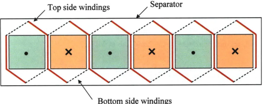
Figure 2-5(a) illustrates what one phase of the energy harvester's winding arrange-ment would look like when manufactured using a two-layer flexible printed circuit implementation provided by Altaflex. The windings are double sided, with sets of conductors on one side of a separating layer connecting with sets of conductors on the other side to form the individual coils. Typically a multiphase arrangement of windings would be used to maximize the amount of energy converted by the energy harvester. The winding pattern over a single magnet pole for a six phase winding arrangement is shown in Figure 2-5(b).
Top side windings
/ Separator
' Bottom side windings
(a) Illustration of one phase of the energy harvester winding arrangement which comprises of six coils. The solid conductors are on the top, and the dashed conductors are on the bottom. Connections between the two layers are made with plated-through vias shown as black dots in the figure.
0 00 I; -I
End Windings
L I IBottom Side
Windings
\N
Active
Windings
Top SideWindings
(b) Winding pattern over a single pole for a six phase winding arrangement manufactured using the Altaflex winding process.
Figure 2-5: Configuration of the multi-pole flexible printed circuit board.
Figure 2-6: Flexible printed circuit board under microscope. The winding layout was
drawn by David Otten, a research scientist in the Lang Lab, and manufactured by
Altaflex.
Design Rule High Density Standard
Minimum Trace / Space (Subtractive Etch) 0.001"/0.0015" (0.33 oz.) 0.0015"/0.002" (0.33 oz.) Minimum Via Hole Diameter (Before Plating) 0.0015" (UV Laser) 0.003" (UV Laser) Minimum Blind Via Diameter (Before Plating) 0.004" (UV Laser) 0.008" (UV Laser) Trace to Edge Distance 0.001" (UV Laser) 0.003" (UV Laser) Trace to Edge Tolerance 0.0005" (UV Laser) 0.001" (UV Laser) Cover Layer Aperture Positional Tolerance 0.001" (Laser Defined) 0.003" (Cover Film)
Table 2.1: Altaflex flexible printed circuit board process capabilities and tolerances.
Figure 2-5(b) illustrates that the winding pattern for a multiphase winding
ar-rangement can be very complicated. Some important features of the winding process
include the need for end windings. These are necessary in order to allow the coils to
complete, but they add to parasitic loss in the windings. Other winding design
dimen-sions include wire thickness, wire width, multi-phase and multi-layer configurations.
As with all designs, there are also design constraints due to the process capabilities.
Table 2.1 shows an abstract of the process capabilities and tolerances provided by
Altaflex
2. For our harvester coil design, the most critical one is the trace to insulator
space ratio. This process constraint limits the maximum coil density and the lowest
possible parasitic resistance and effectively limits the output power of the harvester.
These design flexibilities and process constraints were fully explored in our work and
incorporated into our optimization program written in MATLAB. The code can be
found in Appendix A.
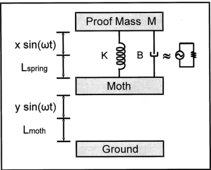
Figure 2-7: The resonant converter modeled as a spring-mass-damper system.
The three-phase windings as fabricated by Altaflex are shown in Figure 2-6. They are fabricated from two-sided 37-mm-thick printed-circuit copper on 13-mm-thick Kapton. Each phase winding contains two coils in a figure-eight pattern that can link flux from two magnets. The windings match the 9.5-mm length of the magnets, and their vertical pitch matches the 1.8-mm magnet width as shown in Figure 2-4(c). The winding terminations are located to permit easy stacking of a multi-layer winding. The generator in Figure 2-4(a) has two stacked layers.
2.3.2
Spring-mass-damper Model
The mechanical model of our resonant converter is shown in Figure 2-7. The body vibration of the insect can be modeled as a sinusoidal vibration source with an am-plitude of y relative to the inertial ground and angular frequency of w. On top of the insect, lays a resonator with proof mass M and spring constant K. Lsping is the unstressed length of the spring, and Lmoth is the average height of the moth during flight.
The proof mass vibration can also be modeled as sinusoidal with an amplitude
Proof Mass M
x
sin(t)
Lspring
Moth
y
sin(ot)T
Lmoth
I
Ground
I
x relative to the moth's body and frequency of w, same as the moth vibration fre-quency. The electromagnetic coupling, which converts kinetic energy to electrical energy, along with energy loss in the harvesting system is represented as a viscous damper of damping coefficient B (newton-seconds per meter). The total force on the proof mass Fot, consists of the spring force F, and the damping force Fd. We can then express the total mechanical force Fot~ as
Ftot = Fs + F (2.2)
The spring force F, can be expressed as
Fs = -kx (2.3)
The damping force may be mathematically modeled as a force synchronous with the velocity of the object but opposite in direction to it. If such force is also proportional to the velocity, as for our simple mechanical viscous damper (dashpot) model in Figure 2-7, the force Fd may be related to the velocity u by
Fd = -Bu = -B1 (2.4)
Finally, treating the proof mass as a free body and applying Newton's second law, the total force Fot is
Ftot =
ma =m
(x+
y
+
Lmoth+
Lspring)" = m(x+
y)" (2.5)where m is the mass of the proof mass, and a is the acceleration of the proof mass relative to the inertial ground.
With the relationships given in Equation (2.3), (2.4) and (2.5), we can rewrite Equation (2.2) as
Fot = Fs + Fd (2.6)
-m - # = m -, z+ B -, + k - x (2.7)
Solving the differential equation (2.7) in sinusoidal state, we get
mw2 -Y = -mw2 -
X +
jwB
-X + k -
X (2.8)where X and Y are the complex sinusoidal amplitudes of x and y, respectively. At resonance, the first and third term on the right hand side of Equation (2.8) cancel. Since we are interested in the amplitude of the resonator vibration, we obtain
X = (2.9)
B
The mechanical power going into the damper is
P = -Bw2X2 (2.10)
2
We can combine Equation (2.9) and (2.10) and obtain the following relationship
P = Bw2 M2W2Y 2 (2.11)
2 ( B2
mY~w W (2.12)
2B
From Equation (2.12), we can see that the only design variable remaining is the damping factor B. Y and w are respectively the vibration amplitude and frequency of the moth which are given constants. On the other hand, the mass of the resonant converter m is limited by the moth's mass carrying constraints given in Section 2.1. Therefore, in order to harvest more mechanical energy through the damper, a lower damping factor is more desirable. However, from Equation (2.9), this results in a large amplitude X. There is therefore a maximum harvester power output given a
maximum X and a maximum m. If we combine Equations (2.9) and (2.12), we can get the following relationship
P = -mwAXy (2.13)
2
which expressed power in terms of dimensional constraints. By applying a vibration amplitude X = 5 mm and proof mass m = 0.2 g to Equation (2.13), we can get an estimated output power of 1.936 mW.
2.3.3
Electromagnetic Analysis
In this section, we will focus on analyzing the electromagnetics of the resonant gen-erator. The amount of power that can be extracted from the energy harvester is a function of the voltage that can be induced by the resonant generator and the re-sistance of the harvester's windings. For an electromagnetic energy converter the voltage generated, V, can be expressed as the time derivative of the flux linkage A such that
V = -A (2.14)
dt
This equation can be reorganized asV = --
dy
(2.15)dy dt
where y is the relative position between the magnet and the winding as shown in Fig-ure 2-9. The relationship in Equation (2.15) indicates that the voltage is propotional to the displacement derivative of the flux linkage and the relative velocity between the magnet and the winding. This means that it is desirable to have the energy harvester's windings passing through a strong magnetic field as fast as possible. In addition, the key to understanding the operation of the resonant converter, is to de-termine L, or equivalently A(y). A number of magnetic designs were studied during the course of this work in an effort to identify the most suitable design for the cyborg
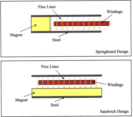
Flux Lines Windings Magnet Steel Springboard Design Flux Lines Windings Magnet Steel Sandwich Design
Figure 2-8: The springboard and sandwich magnetics designs that were studied as
part of the design process for the energy harvester. In these two designs, the windings
move into and out of the page.
moth energy harvester. The two that were examined in most depth are shown in
Figure 2-8.
The first design is referred to as the springboard design, while the second design
is referred to as the sandwich design. In both designs, the windings move into and
out of the page. The magnets, on the other hand, are stacked into the page with
alternating magnetic polarization from magnet to magnet as shown left-to-right in
Figure 2-5(a). Of the two magnetics designs, it is the sandwich design that results in
a magnetic field distribution that is more suitable for use within the energy harvester.
The reasons for this are due mainly to the fact that the sandwich design results in
a more uniform magnetic field distribution in the air-gap than is the case with the
springboard design.
Evaluation of the magnetics designs was carried out using the COMSOL
Mul-tiphysics (CMP) finite element method software suite. Using CMP it was possible
to analyze the magnetic field distributions in the air-gap through which the energy
X 10-3
- x 10-3
Steel
Air-gap
Maget
y V_
x
Figure 2-9: Illustration of a six pole sandwich type magnetics design in the CMP user
interface. These magnets each have a magnetic flux density of 1.5 T. Their magnetic
flux is in the z-direction and the magnetization reverses from magnet to magnet in
the y-direction of travel to form a six-pole magnetic structure. Our final two designs
were three-pole and four-pole magnetic structures.
harvester windings would pass. The power and design utility of CMP lies in the fact
that the program allows the fast evaluation of how changes in the magnetics design
affect the magnetic field distributions in the air-gap. Figure 2-9 illustrates what a
sandwich type magnetics design looks like when drawn using the CMP user interface.
The approach which we took to evaluate the A inside the magnetic core was to
take a few critical geometries of the magnetic core and use COMSOL to determine the
peak magnetic flux density. This would give us a table of magnetic flux densities
cor-responding to core geometries as shown in Table 2.2. Then, we can use interpolation
to find the magnetic flux density peaks for other geometries. This table is used in the
simulation described in Section 2.3.4 as a look-up/interpolation table to determine
the magnetic field strength. The magnetic flux inside the core did not saturate in the
COMSOL simulations.
A very important point that must be mentioned here is that increasing the air-gap
MT / PP .2 0.3 0.4 0.5 0.6 0.7 10.8 0 0 0 0 0 0 0 0 1 0.165 0.216 0.267 0.377 0.487 0.594 0.700 2 0.188 0.280 0.371 0.526 0.680 0.840 1.000 3 0.195 0.347 0.500 0.625 0.750 0.910 1.070 4 0.216 0.362 0.507 0.628 0.750 0.897 1.043 MW
/
PP 5 0.238 0.376 0.513 0.632 0.750 0.883 1.017 6 0.260 0.390 0.520 0.635 0.750 0.870 0.999 7 0.300 0.400 0.530 0.635 0.750 0.860 0.999 8 0.300 0.400 0.530 0.635 0.750 0.850 0.999 9 0.300 0.400 0.530 0.635 0.750 0.840 0.999 10 0.300 0.400 0.530 0.635 0.750 0.830 0.999Table 2.2: Average magnetic flux density table for different magnetic core geometries. The average magnetic flux densities were measured in the middle of the air gap where the coils will be placed. Each magnet has a magnetic strength of 1.5 T. MT, MW and PP are respectively the magnet thickness in the direction of the magnetic flux, the magnet width and the magnetic core plate-to-plate distance.
A 100 pm air-gap increase would lead to an average magnetic flux density decrase of 0.1T. Therefore, fabricating a small air-gap device would be a big challenge for the project. Nevertheless, this means that for any given energy harvester design, it is desirable to have as small an air-gap as possible. Alternatively, if a larger air-gap is required, a thicker magnetic material is needed to create sufficient magnetic flux density in the air-gap. The tradeoff is an increase in the total mass. Therefore, an optimization of the tradeoff between power and mass is required to determine the optimal solution for our design with manufacturing constraints having a significant influence.
2.3.4
Simulation
In order to find the design that can generate the most power while satisfying the moth payload mass and size limitations, and all fabrication limitations, we implemented an optimization process in MATLAB code shown in Appendix A. The optimization sweeps all possible design parameters including core and magnet dimensions, coil configurations and the resonator vibration amplitude. Design rules of the coil, shown in Table 2.1, and the resonator vibration amplitude limit, defined by the moth payload shape limit, were also taken into account.
For each design, the core and magnet dimensions were first applied to a magnet flux density look-up table, generated by magnetic simulations in COMSOL, to de-termine the magnetic flux density that passes through the coils. Once the magnetic flux density is determined, the simulation substitutes different coil configurations, vibration amplitudes and load resistances into the mechanical model to obtain the output voltage and power. The output voltage is derived from Equation (2.14), and the average output power is derived from this voltage, the harvester resistance and the load resistance.
An important point that must be made here is that the open circuit voltage of the harvester, is not a constant AC voltage source. This is because the load resistance will affect the vibration amplitude of the harvester. A smaller load resistance will create a larger damping effect on the harvester and as a result decrease the amplitude and velocity of the vibration. The decreased velocity will then decrease the open circuit voltage. Since the open circuit voltage is a function of the load resistance, the maximum output power does not necessarily happen at the matched load condition. We can express the output voltage across the load resistance as follow
Voad
=
a
-V
(2.16)
1 + a
where Vload is the voltage across the load, a is the ratio between the load resistance and the output resistance of the harvester, and V is the open circuit voltage. The load voltages were calculated for different vibration amplitudes and load resistances of the same harvester design. Therefore for each harvester design, there exists an optimal load resistance which yields maximum output power. This phenomenon is confirmed in experiments in Section 2.4.2.
Finally, we sum up the mass of all the components and calculate the output power from the load voltage. Therefore, for each design, we would have its output power and total mass along with specific design details.