Acoustic Noise Suppression for
Helicopter Communication Systems
by
Jeffrey Thomas Evernham
S.B., Aeronautics and Astronautics Massachusetts Institute of Technology, 1991Submitted to the Department of Aeronautics and Astronautics in partial fulfillment of the requirements for the degree of
Master of Science in Aeronautics and Astronautics at the
MASSACHUSETTS INSTITUTE OF TECHNOLOGY
September 1992
@ Jeffrey T. Evernham, 1992. All rights reserved.
The author hereby grants to MIT permission to reproduce and to distribute publicly copies of this thesis document in whole or in part.
A
uthor ....
-
.
...
... ...
Department of Aeronautics and Astronautics
August 25, 1992
Certified by ... -• - •-. .-....- Harold L. Alexander, Assistant Professor Department of Aeronautics and Astronautics Thesis Supervisor
Certified by... ...w... ... ...
Richard S. Teal, Staff Engineer Boeing Defense and Space Group, Helicopters Division Thesis Supervisor
Accepted by... ... .. .... ...
. . Professor Harold-Y, Wachman, Chairman
Department Graduate Committee
fro
MASSACHUSETTS INSTIUTE
NOV 18
1992
Acoustic Noise Suppression for
Helicopter Communication Systems
by
Jeffrey Thomas Evernham
Submitted to the Department of Aeronautics and Astronautics on August 25, 1992, in partial fulfillment of the
requirements for the degree of
Master of Science in Aeronautics and Astronautics
Abstract
This document describes the design and implementation of three digital acoustic noise suppression systems for the Boeing CH-47D Chinook helicopter's interphone system. The Chinook's forward transmission produces narrowband noise spikes, or gear whine, which change frequency as the gearbox's rotation rate varies. Three algorithms are explored as possible methods to remove this changing narrowband noise from the pilots' microphone signal in order to increase the signal-to-noise ratio
and intelligibility of the pilots' voices. These algorithms are the Least Mean Squared Adaptive Noise Cancellation (LMS) algorithm, the Tracking Filter (TF) algorithm, and the Variable Sampling Rate (VSR) Algorithm.
The LMS and TF algorithms, were implemented in computer simulation and in real-time hardware, and were tested with four inputs: sinusoidal, speech, cockpit noise, and cockpit interphone (speech plus noise). A normalized-frequency VSR al-gorithm was studied as well, but hardware limitations prevented its implementation as a real-time system. The parameters of the LMS and TF systems were varied, and the outputs of the resultant systems were compared with one another and the unfiltered signal. Also, maximum-attenuation systems were implemented to examine the distortion caused by a large number of filters.
The LMS and TF algorithms were found to reduce the noise content at the noise spike frequencies by 10-35 dB, without significantly affecting the signal content of the pilots' voices. The systems were successful at tracking the RPM changes of the forward transmission in order to maintain suppression of the notch frequencies as they changed over time. The noise reduction capability of the two algorithms were comparable for very narrow (less than 5 Hz) band noise, whereas the TF algorithm provided better attenuation for larger bandwidths. However, both systems added distortion to the signal, in the form of a ringing sound at the suppressed frequencies. The ringing sound was stronger for the LMS algorithm than for the TF approach, although the TF algorithm removed more of the pilots' speech frequencies. Using equivalent-parameter systems, tuned to provide a subjective best tradeoff between noise reduction and distortion, the TF algorithm resulted in a slightly better quality
output. These two algorithms do (and the VSR algorithm promises to) improve the sound quality of the CH-47D interphone system, and may be useful in other, similar applications.
Thesis Supervisor: Harold L. Alexander, Assistant Professor Title: Department of Aeronautics and Astronautics
Thesis Supervisor: Richard S. Teal, Staff Engineer
Acknowledgments
Thanks must be extended to the countless people at Boeing Helicopters who helped
me througout this project, but mentioning every one of them would kill too many
trees. I will list many on this page; those whom I have overlooked, please accept
my apologies. So, thanks go to Angelo "Bring that Back" Drammissi, for ordering
parts and hardware for the real-time system, and providing assistance in circuit
mod-ification. To Clark Sechler, also for ordering material and constructing circuits. To
Ed "The Handyman" Nester, who gave his support to just about every aspect of the
real time system and many VAX-IBM-Mac-Other interface tricks, helping to diagnose
problems, teach me how to use equipment, debug hardware interfaces, and
occasion-ally providing much-needed stress relief. To Blair "Hardware is Heaven" Harro, who
selflessly devoted time and expertise to help debug the multiple hardware problems
that occurred during development, from VME interfaces to zero crossing detectors.
To Ken "Wire Wrap" Wochele, who designed, constructed, tested, and helped (often
on his own time) debug the zero crossing detection systems for both the MIZAR card
and the PC interface; good luck with your thesis! To Bob Spencer, who furnished help
with the acoustics side of the project, providing equipment and observations, as well
as making suggestions for the document. To Harry Sternfeld, for his guidance with
the project's acoustics side, and also for reading drafts of the thesis. To Perry
Zigin-bein, for acoustics help and for digitizing the CH-47 noise on the VAX for analysis.
To Nick Albion, for sparking my interest in the initial idea of reducing noise in the
CH-47 cockpit. To Rich "Yes, I've got one minute" Teal, who also got me interested
in the idea, and who provided technical support for the theory and implementation
of the real time systems. To Rob "You're Back!" Cloutier, for encouragement and
support throughout- my time at Boeing. To Dorothy "Time Card" Carroll, for making
the ways of the business world easier for a relative newcomer. To Walt Ballauer, for
allowing flexibility in my work schedule during the long hours of thesis creation. To
the late John Senese, for help with the cockpit interphone system. To Joe Schluck,
who assisted me greatly with setup guidance for flight testing, helped to make the
recordings themselves, and who gave me my second helicopter flight (the first on a CH-47). To Phyllis Schultz, for her help with the EIP program from the Boeing side, and a smiling face of encouragement every time I saw her. To Steve "Alarm Clock" Llorente, for providing a haven away from work, stress-relieving tennis, and for waking me up at 7:00 after those 16-hour workdays.
Thanks to those, at M.I.T. and at Boeing, who allowed me to alter the EIP schedule to suit my needs - the project would have suffered greatly otherwise.
There are also many people outside of Boeing who this project would have been impossible without. I extend thanks to Steve Curtain at Ariel, for providing an excel-lent product and even better support during the purchasing and development stages of the project. To Steve "Athena God" Ellis, who helped to debug my MATLAB sim-ulation code and explained how to make the MIT-Boeing computer connection work. To Liz "What is it now?" Zotos, for handling the bureacracy of mixing business with education. To Tim "Yes No Ok Cancel" Hazen, my long-time partner in DSP and digital circuit labs, for help with DSP techniques, analog filter design, and digitizing the signals for use in the simulation. To Will "Burr" Gorgen, my long-time partner in Aeronautics (among other things), for taking care of MIT-related duties while I was at Boeing, most notably helping with transfer of data and IATEXcompilation of thesis drafts - now it's your turn. To Jen, for everything she's done for me, but especially her support and understanding during the stressful long hours and weeks of thesis preparation. To Kevin "AutoCAD" Evernham, for the 3-D rendition of the lower planetary gear system. To my parents, for their support, concern, encouragement, and guidance over the last 22 years - much of who I am and what I have accomplished would have been impossible with any others. And, of course, to Sandy "Thesis-by-Mail" Alexander, for his guidance, explanations, instruction, suggestions, and ideas for all aspects of the noise reduction project, and for helping make this document
readable and understandable.
I can only hope that all those whom I have mentioned have had as much fun as I have had, and not as much frustration.
Contents
1 Introduction 9
1.1 Project Overview ... 9
1.2 Problem Description ... 11
1.2.1 Noise in Helicopter Cockpits and a Potential Solution .... . . 11
1.2.2 Types of Noise and What is Affected . . . . . .... .. . . . 12
1.2.3 CH-47D Cockpit Noise Characteristics . . . . 13
1.3 Existing Technologies for Cockpit Noise Reduction . . . . ... . . 14
1.3.1 Suppressing Direct Noise ... 15
1.3.2 Suppressing Indirect Noise ... ... . . 18
1.3.3 Summary of Noise Suppression Capability ... .. 20
1.4 Proposed Solutions ... 22
1.4.1 Adaptive Noise Cancellation . . . . 22
1.4.2 Algorithms Examined ... 23
1.4.3 Testing Procedures and Results ... . . . . . 24
1.5 Reader's Guide to Document ... 25
2 CH-47D Noise Characterization 27 2.1 General A alysis ... 27
2.1.1 Cockpit Noise Spectra ... 27
2.1.2 Primary Noise Sources ... 32
2.2 Forward Transmission Gear Whine Analysis . . . . 32
2.2.1 Gearbox Description ... 32
2.2.3 Prevalent Harmonics ... 39
2.3 Reduction Goal ... 42
2.3.1 Rotation Rate Variance Characterization . ... 42
3 Proposed Solutions 47 3.1 Introduction to the Noise Suppression Algorithms . ... 48
3.1.1 LMS ANC Algorithm ... 48
3.1.2 TF Algorithm ... ... 49
3.1.3 VSR Algorithm ... 50
3.2 Modulate-Filter-Demodulate Algorithm . ... . 50
3.3 Least-Mean-Squared Adaptive Noise Cancellation . ... 53
3.3.1 Transfer Function Derivation . ... . 54
3.3.2 Implementation ... 58
3.3.3 Design Considerations ... ... 59
3.3.4 LMS Algorithm using Ambient Noise as Reference Signals . . 61
3.3.5
LMS Algorithm using Sinusoidal Reference Signals ...
62
3.4 Tracking Notch Filters ...
63
3.4.1
Transfer Function Derivation . ...
67
3.4.2 Design Considerations ...
68
3.4.3 Tracking Filter Algorithm using Finite Impulse Response Filters 72 3.4.4 Tracking Filter Algorithm using Infinite Impulse Response Filters 72 3.5 Variable Sampling Rate Filtering . ... . 77
3.5.1 Transfer Function Derivation . ... 78
3.5.2 Design Considerations ... 79
3.5.3 Variable Sampling Rate Algorithm using IIR Notch Filters . . 81
3.5.4 .. Simulation of System at Nominal Frequencies . ... 82
3.6 Reference Signal Analysis and Obtaining Frequency Information . . . 84
3.6.1 Required Signal Characteristics . ... 84
3.6.2 Implications for Reference Signal Selection . ... 87
4.1 Choosing the Reference Signal ... ... 92
4.1.1 Transmission Accelerometer . ... 92
4.1.2 Blade Tracking Signal ... 93
4.1.3 Aircraft Power ... 94
4.1.4 Oil Pump Ripple ... 94
4.1.5 Rotor Tachometer Signal . ... .. 94
4.2 Data Recording ... 96
4.3 Simulation and Modelling ... 97
4.3.1 Implementation Considerations . ... 98
4.3.2 Simulation of the Least Mean Squared Algorithm ... 102
4.3.3 Simulation of the Tracking Filter Algorithm . ... 102
4.3.4 Simulation of the Variable Sampling Rate Algorithm .... . 104
4.4 Real-Time Implementation ... . 105
4.4.1 Frequency Determination System for LMS and TF Algorithms 105 4.4.2 Frequency Multiplication System for Variable Sampling Rate Algorithm ... 106
4.4.3 Implementation on Texas Instruments TMS32020 Microprocessor 1l08 4.4.4 Implementation on Motorola DSP56001 Microprocessor . . . . 108
5 Results, Conclusions, and Recommendations 110 5.1 Implementation ... 110
5.2 Results ... .. .. . . . . .. . . . .. .. .. . .. . . . .. . 112
5.2.1 Frequencies Suppressed and Filter Characteristics ... . 115
5.2.2 Frequency Response and Input/Output Spectra ... . 117
5.3 Conclusions ... 129
5.3.1 -Subjective Results ... .. 129
5.3.2 Comparison of the Three Algorithms . ... 130
5.4 Recommendations for Future Work . ... 134
5.4.1 Real-Time Implementation and Testing of the VSR Algorithm 135 5.4.2 Error Reduction, Update Rate improvements of FDS ... . 135
5.4.3 Flight Testing ... ... .... .... 136
5.4.4 LMS Algorithm with Delayed-Noise Reference Signals ... 136
5.4.5 Characterization of Gearbox and Interphone Noise ... . 137
5.4.6 Combining Noise Reduction Techniques . ... 138
List of Figures
1-1 Boeing CH-47D Chinook Tandem-Rotor Helicopter ... 15
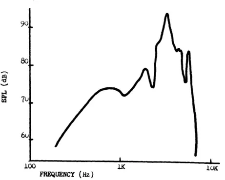
1-2 Transfer Function of Standard CH-47 Interphone System ... 20
1-3 Transfer Function of Improved CH-47 Interphone System ... 21
2-1 Frequency Spectrum of CH-47D Cockpit ... 31
2-2 Close-up of Frequency Spectrum Near 1450 Hz ... 31
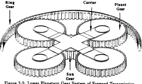
2-3 Lower Planetary Gear System of Forward Transmission . . . . . .. . 34
2-4 Gear System of Forward Transmission (Side View) ... 34
2-5 Two Interlocking Gears ... 35
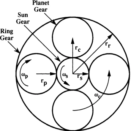
2-6 Overhead View of a Typical Planetary Gear System ... 36
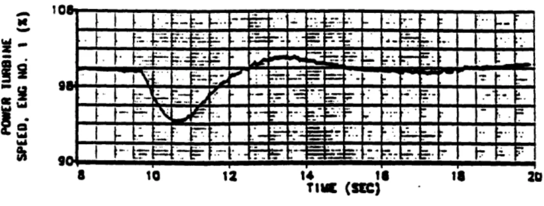
2-7 Strip Chart Record of Transmission Rotation Rate During Jump Takeoff 46 3-1 Block Diagram of the Modulate-Filter-Demodulate (MFD) Algorithm 51 3-2 Block Diagram of the Adaptive Noise Cancellation Algorithm . ... 54
3-3 Block Diagram of LMS Algorithm for Multiple Notch Filters ... 55
3-4 Pole-Zero plot of GLMs(z) for a = .8 . . . . 58
3-5 Bode Response of One-Notch LMS Algorithm at Constant Frequency 64 3-6 Bode Response of Five-Notch LMS Algorithm at Constant Frequency 65 3-7 Block Diagram of Tracking Filter Algorithm ... 65
3-8 Block Diagram of TF Algorithm for Multiple Notch Filters ... 66
3-9 Pole-Zero plot of GTF(z) for a = .8 ... 69
3-10 Bode Response of High-Order IIR Lowpass Filter and its use in the TF Algorithm ... 71
3-12 Bode Response of One-Notch TF System with First-Order IIR Lowpass
Filters at Constant Frequency ... 75
3-13 Bode Response of Five-Notch TF Algorithm with Five First-Order IIR Lowpass Filters at Constant Frequency . ... . . . 76
3-14 Pole-Zero plot of GvsR(z) for a = .8 ... 80
3-15 Bode Response of Normalized Five-Notch VSR System ... 83
4-1 Schematic of Recorder Connections . ... 97
4-2 Linear Interpolation of Digitized Rotor Tachometer Signal ... 99
4-3 Digitally Calculated Rotor Tachometer Frequency . ... 101
4-4 Smoothed Rotor Tachometer Frequency . ... 101
4-5 Frequency Response of Simulated Five-Notch LMS Algorithm to CH-47D In-Flight Data ... 103
4-6 Frequency Response of Simulated Five-Notch LMS Algorithm to CH-47D Takeoff Data ... 103
4-7 Frequency Response of Simulated Five-Notch TF Algorithm to CH-47D In-Flight Data ... 104
4-8 Frequency Response of Simulated Five-Notch TF Algorithm to CH-47D Takeoff Data ... 104
4-9 Block Diagram of Frequency Determination System . ... 105
4-10 Block Diagram of Frequency Multiplier System . ... 107
5-1 Frequency Response of "Optimized" Real-Time LMS and TF Algorithms 120 5-2 Frequency Spectrum of CH-47D Cockpit Noise . ... 121
5-3 Frequency Spectrum of Cockpit Noise after "Optimized" LMS Filtering 122 5-4 Frequency Spectrum of Cockpit Noise after "Optimized" TF Filtering 123 5-5 Frequency Spectrum of CH-47D Cockpit Interphone System .... . 124
5-6 Frequency Spectrum of Interphone after "Optimized" LMS Filtering . 125 5-7 Frequency Spectrum of Interphone after "Optimized" TF Filtering . . 126
5-8 Frequency Spectrum of Interphone after Maximized LMS Filtering . . 127
List of Tables
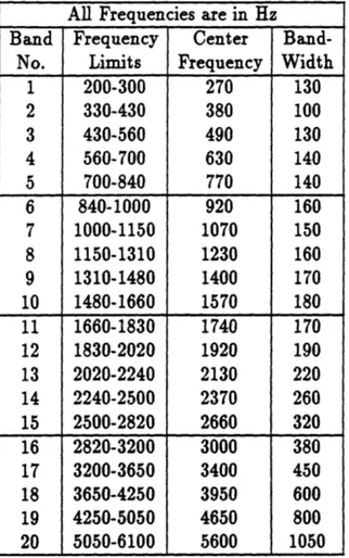
2.1 Frequency Bands of Equal Contribution to Speech Intelligibility . .. 30
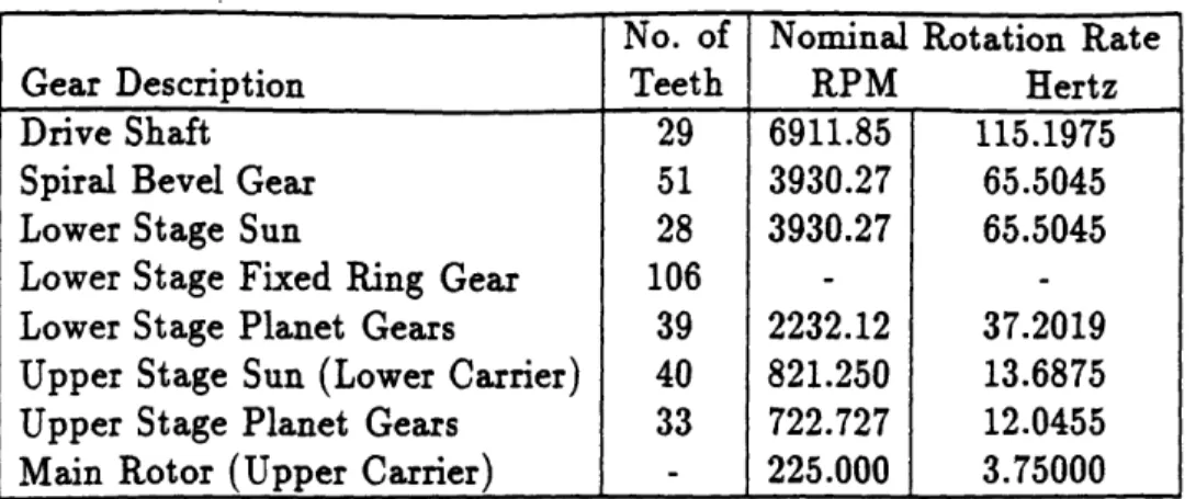
2.2 Teeth Per Gear and Rotation Rates of Forward Transmission Gearbox 38
2.3 Fundamental Gear Mesh Frequencies of Forward Transmission Gear-box for Nominal Rotation Rate ... 40 2.4 Nominal Gear Mesh Frequencies and Harmonics of Forward Tranmission 40 2.5 List of Noise Spikes, Approximate Decreasing Amplitude ... 43 5.1 Filter Characteristics of "Optimized" LMS and TF Algorithms .. . . 116
Chapter 1
Introduction
1.1
Project Overview
This document describes the development, testing, and results of applying adaptive
notch filter techniques to reduce noise in the interphone system of the Boeing CH-47D
Chinook helicopter. Gear whine generated by the forward transmission produces high
amplitude, narrowband noise spikes which are picked up by the pilots' microphones
and mask their speech, reducing the signal to noise ratio (SNR) in the cockpit radio
system and decreasing the intelligibility of pilots' speech. As the rotation rate of the
transmission changes during wind gusts and manuevers, the gear mesh frequencies
change, "sliding" up and down the frequency spectrum.
Three adaptive filtering techniques were used in an attempt to suppress the noise
spikes while leaving most of the desired signal intact, with the hope of increasing
the SNR and the intelligibility of the pilots' speech. First, the Least-Mean-Square
Adaptive Noise Cancellation (LMS ANC) algorithm was applied to implement notch
filters of constant bandwidth whose center frequencies could be controlled by changing
the frequencies of reference inputs. The LMS algorithm determines the correlation
between the input and reference inputs, and subtracts the integral of this value from
the input. The frequencies of the reference inputs were proportional to the rotation
rate of the gearbox, allowing the filters to track the frequencies of the gear mesh noise.
Second, the Tracking Filter (TF) algorithm, which utilizes quadrature modulation
and a lowpass filter in a feedforward manner to obtain a notch filter, was applied in a similar manner. Last, a Variable Sampling Rate (VSR) algorithm was implemented, which utilized fixed-coefficient notch filters and a sampling rate proportional to the transmission rotation rate. Because the frequencies of digital systems are normalized to the sampling frequency, changing the sample rate changes the frequencies of the filters. The sample rate was proportional to the gearbox rotation rate, allowing the filters to track the gear mesh noise as well.
The three algorithms were first modelled on a computer, to explore their poten-tial, evaluate the effects of nonidealities, and compare the results. Then, the LMS and TF algorithms were implemented in hardware systems and run in the labora-tory with recordings from the CH-47D helicopter. The real-time VSR algorithm was not fully implemented due to unforseen hardware limitations of the development sys-tem. The VSR algorithm required the least computation time', although obtaining a high-frequency, stable signal to drive the sampling rate required careful design of a phase-locked loop frequency multiplier. The LMS algorithm needed a moderate amount of calculation time, and had better frequency-response characteristics than the other two. The TF algorithm required the most computation, but had a better subjective effect on the interphone signal than the LMS approach. All three algo-rithms proved satisfactory in ideal and nonideal (limited precision) implementations, and when designed carefully, produced comparable reductions in the background noise of the interphone system without greatly affecting the pilots' speech2. While formal intelligibility tests were not conducted, the LMS and TF algorithms improved the quality of the interphone signal, providing 10-35 dB of attenuation at the noise spike frequencies, while introducing low to moderate amounts of distortion to the pilots'
speech. The distortion was noticeable as attenuated speech frequency bands and a ringing sound present at the attenuated frequencies. The ringing was somewhat more
'While the system was not able to run with the variable sampling rate, it was implemented in a normalized form with a constant sampling frequency. Thus, the LTI characteristics of the algorithm were evaluated, but the time-varying effects remain unstudied.
2The normalized-frequency VSR algorithm had effects very similar to the TF algorithm, but its
pronounced with the LMS algorithm, making the TF algorithm slightly more pleasing to the ear.
1.2
Problem Description
The harsh environment of a helicopter cockpit makes it difficult for the pilot and copilot to concentrate on the jobs they must perform. They must constantly moni-tor their instruments, surroundings, and crew, while enduring continuous vibration, movement, and loud noise. The tasks and environment demand a great deal from the pilots, and any device to lessen the strain they must endure is a welcome addition. Noise is perhaps one of the least controllable and most annoying of these problems, causing increased fatigue, shifts in hearing threshold levels, and reduced intelligibility of communication[15, 25]. Repeated exposure without personal hearing protection (earmuffs, earplugs, etc.) to the noise levels in many of today's helicopters would cause permanent hearing damage. These high levels of noise exist because of system design tradeoffs. A helicopter that was almost noise-free internally would result in extreme performance penalties, so sacrifices (such as the requirement to wear per-sonal hearing protection) are made in order to maximize the aircraft's potential. As a result, high noise levels are present in many of today's helicopters, and the CH-47D is no exception.
1.2.1
Noise in Helicopter Cockpits and a Potential Solution
Excessive noise in the cockpits of helicopters contributes to, among other things, reduced intelligibility of pilot and copilot speech[15, 25, 44]. This occurs becausemicrophones used by the pilots and crew pick up noise inside the helicopter, and
transmit this noise over the helicopter's communication system. Many approaches
have been tried in the past to reduce this unwanted noise, but as the lifting powerof new helicopters increases, previous solutions become less and less effective, and
new techniques are sought[40, 44]. A new approach has become feasible with the
advent of high-speed Digital Signal Processing (DSP) microprocessors, utilizing the
fact that the noise spectrum is dominated by narrowband noise spikes generated by the forward transmission[7, 25, 41, 44]. These noise spikes degrade the signal-to-noise ratio, making the pilots' speech difficult to understand. Notch filters may be used to decrease the contribution of this narrowband noise to the transmitted signal, without greatly affecting the signal power of broadband speech. This decreases the noise power while leaving the signal power relatively unchanged, resulting in a higher signal-to-noise ratio and better intelligibility. As the rotating speed of the transmission varies over time due to wind gusts and maneuvering, the notch filters must change their center frequencies as well in order to continue suppressing the gear mesh noise. In other words, the filters must track the rotation speed of the transmission. Filters with changing characteristics are difficult to implement using analog techniques, but are quite feasible with the use of DSP algorithms.
1.2.2
Types of Noise and What is Affected
The noise present in the cockpit gets to the pilots' ears by two routes: direct and indirect[25]. Direct noise is the sound that travels from the noise source to the eardrum directly, most often through the pilots' helmet and earcups. Indirect noise is the sound that gets picked up by the pilots' microphones, travels electronically through the communication system, and is then converted to an audible signal by the speaker in the pilots' earcup. Direct noise is experienced only by the pilots and crew in the helicopter, whereas indirect noise is heard by anyone listening to the communication system: the pilot and copilot as well as air traffic controllers, other pilots, ground troops, etc. Both noise sources contribute to reduced intelligibility for the pilots, but only the indirect noise makes the pilots harder to understand by others. Furthermore; this indirect noise, because it is combined in the microphone with what the pilots say, creates a major obstacle to the use of voice recognition (VR) systems. VR systems are becoming feasible as a method to reduce pilot workload in airplanes, but extending their use to helicopters has been hindered by the extremely noisy cockpit environment. If this noise could be suppressed, perhaps VR systems could become an integral part of helicopter avionic systems, and some of the demands
imposed on helicopter pilots could be reduced.
1.2.3
CH-47D Cockpit Noise Characteristics
In examining how to reduce noise in the cockpit, the sources of the noise must be identified. For all helicopters, there are three primary noise sources: the sound of
the rotor blades moving through the air, the turning of the gears in the transmission,
and the turning of the engine components[44]. The rotors produce loud but very
low frequency vibrations which are often transferred to the entire fuselage of the
helicopter. Noise from gears in the transmission tends to be narrowband, but has
substantial noise power at several frequencies. Engine noise has high power, due
largely to its wide bandwidth, and is primarily located in high frequency ranges.
The helicopter used in this project was the Boeing CH-47D Chinook helicopter,
which produces a great deal of noise due to its large size and lifting capability. This
aircraft generates noise levels as high as 115 dB and 100 dBA
Sinside the cockpit, even
with full acoustic treatment[7, 15, 41, 44]. This is mostly due to the large size and
lifting capacity of the helicopter; the noise of rotors, transmissions, and engines is a
function of the power they must provide or transfer. In fact, the noisiest point in the
helicopter is immediately below the forward and aft transmissions [7], and their high
noise levels are largely due to the high power transmitted through the gearbox[24].
The CH-47 is therefore a good choice for testing noise reduction equipment for several
reasons. First, the noise problem is so evident that a minor improvement will be
more noticeable than if the noise were not so severe. Second, noise reduction in
such an environment will provide a greater benefit than a proportional reduction
in a helicopter where noise is not so severe. Third, if the noise suppression system
is capable of reducing such high-amplitude noise, it is also likely to work on lesser
amplitude noises; this is not necessarily true the other way around. Therefore, if a
3Decibels (dB) is a measure of absolute sound pressure level, defined as 20 log
, where spl is
the sound pressure level, and ref is a reference sound pressure level (usually 20 pPa). dBA is the
A-weighted sound pressure level, which takes into account the human ear's varying sensitivity to
different frequencies. While dBA is most important for measuring intelligibility, the actual level in
noise reduction system has the potential for use with various helicopters4, it makes
sense to develop and test the system on a CH-47.
The D-model of the CH-47 has been selected for several reasons. First, it is the most common of the five basic Chinook models, and is manufactured in both military and civilian configurations. Second, they are still being manufactured (unlike the A, B, and C models) and are expected to remain in service for some time. Third, the E model is substantially different, utilizing more modern components, so that a noise reduction system that works on the E model may not work for any of the earlier models.
A diagram of the CH-47D can be seen in Figure 1-1, and shows how the helicopter's
specific configuration makes its noise problems unique. First of all, the gas turbine engines that provide its power are located at the aft of the rather large helicopter, so their contribution to the cockpit noise is relatively small. Secondly, the CH-47D is a tandem rotor helicopter, and therefore has a forward rotor and transmission as well as an aft rotor and transmission. The cockpit and the pilots are located very close to the forward transmission and rotors, and as a result, most of the cockpit noise is generated by these sources. Furthermore, the fact that these sources are so close to the cockpit does not allow room for much soundproofing material to be applied. In fact, the forward transmission sits immediately behind and above the two pilots; a pilot with a long arm could touch the bottom of the gearbox casing while still sitting in his or her seat. As a result, the noise from the forward transmission dominates the frequency spectrum of the cockpit.
1.3
Existing Technologies for Cockpit Noise
Re-duction
Noise in helicopter cockpits is not a new problem. Much time and effort has been devoted to reducing the amount of noise they produce in the first place, and to
'Other helicopters have very similar noise problems; Laskin[24] found the UH-1D's noise is dom-inated by its gearbox as well.
AFT SYUCHKOUIZIUSG SHAFTING 12 SHAFTS) FOIWARD SHAFTII FORWARO TRANSMISSION
Figure 1-1: Boeing CH-47D Chinook Tandem-Rotor Helicopter
suppressing the noise that they do generate. As the focus of this project is to suppress noise that is already present, the sound-reducing design issues of rotors, gearboxes, and engines will not be explored. However, many other approaches have been used to attack the direct and indirect noise that reaches the pilots, and a brief introduction to these techniques is presented in the following sections. Also included is a synopsis of previous literature on adaptive noise cancellation, the noise reduction technique used in this project.
1.3.1
Suppressing Direct Noise
Perhaps the most obvious solution to reducing the effect of noisy machinery is to isolate the machinery from the operating environment, either by distance or sound absorbing and insulating materials. Because of the design of the CH-47, it is not possible to move the pilots further away from the transmission. However, sound insu-lation and blanketing can lessen the noise substantially; soundproofing has obtained
AFT SHAFT COMBINING TRANSMISSION MISSION ES)
reductions of up to 35 dB at speech frequencies in the CH-47 cabin, but cockpit
reductions have been limited to no more than 20 dB
5[40]. But, using this sound
absorbing material has two drawbacks. First, a lot of insulation is required to obtain
substantial dissipation of loud sounds, such as those generated by the tranmission,
and second, the insulation is bulky and heavy. There isn't much room in the CH-47
cockpit to place a lot of insulation, and the weight of the material imposes a
sacri-fice on the performance characteristics of the helicopter. Each additional pound of
soundproofing means that one less pound of fuel or other cargo can be carried. This
can be a difficult sacrifice to make, especially when lives are at stake; helicopter pilots
in Vietnam were known to strip out cabin insulation material in order to obtain as
much performance as possible from the helicopter[44]. As a result, better methods
have long been sought to provide the same benefits as physical soundproofing, but
without its weight and size penalties.
To this end, several alternate and complementary approaches have been found.
The simplest of these is isolating the pilots' ears from the noise source, rather than
isolating the source from the whole cockpit. This is most often done through the
use of insulated helmets and/or noise reducing earcups. Because these treat only the
small area around the ear instead of the entire cockpit, the same noise dissipations
of other insulating techniques can be achieved with much smaller weight penalties.
The attenuation achieved by the standard helmet/earcup combination used on the
CH-47 ranges from under 15 dB below 250 Hz to a maximum of about 50 dB near
3500 Hz[15]
6. The drawbacks of this approach stem from the fact that the
reduc-tion obtainable is largely a funcreduc-tion of the earcup's seal to the pilot's head. The
amount of attenuation is directly related to the integrity and force of the seal, so
attenuating loud sounds requires high-pressure "bonecrusher" headsets that are often
painful and fatiguing, especially when worn for extended periods. Furthermore, while
sEven with 95% surface coverage using 1.5 bT blanketing material, cockpit reductions did not
exceed 20 dB at speech frequencies. This is largely due to the fact that windows are excellent sound
radiators, and the surface of the cockpit of the CH-47 (as with any helicopter) is mostly windows.
"This is typical, as most flight helmets achieve more than 30 dB of attenuation at frequencies
these earcups do a good job of attenuating high-frequency noise (above approx. 1000 Hz)[15], they become less effective as the frequency decreases. So, while such earcups are excellent for relatively low-amplitude, high-frequency noise, the extreme volume and lower frequencies of helicopter cockpit noise (especially that of the CH-47) makes these earcups only a partial solution.
A more recent development has been Active Noise Reduction (ANR). An ANR
system "listens" to the ambient noise present, and drives speakers to send out an identical noise signal, but 180 degrees out of phase with the original signal. This technique attempts to achieve complete elimination of the unwanted noise through destructive interference. These systems can produce reductions (in the pilot's earcup) of 10-20 dB for low-frequency (below 500 Hz) aircraft engine noise[6, 42, 43], these systems have several drawbacks. First, a microphone must be present very close to the point where the noise is to be cancelled7, because displacement between the microphone and the zero-noise location affects the phase of the signals. Obviously, phase errors decrease the effectiveness of the system, and enough error (greater than
90 degrees) can actually lead to constructive interference, which only worsens the
noise. While phase errors do not pose a problem for the use of ANR in an earcup, it does prevent such systems from working in large spaces, such as the cockpit. Second, such systems are limited by their finite response times and the need to listen to the noise present while attempting to cancel it. These two problems can cause positive feedback, where an ANR system actually generates its own noise, causing negative attenuation. For typical systems, this positive feedback can occur at frequencies as low as 1 kHz[42]. Finally, ANR systems do not perform well with extremely high amplitude noise, as the very high sound levels (on the order of 125 dB) can cause the control system to go unstable[43]. Thus, while ANR is attractive for in-the-earcup, low-frequency noise reduction, it does not provide a very good solution to high-frequency, cockpit-wide noise.
7Typically, reduction can only be achieved when there is less than half a wavelength distance
1.3.2
Suppressing Indirect Noise
A limitation of the latter two techniques is that they only attack the direct noise that reaches the pilot's ears. Every time the pilot or copilot tries to talk to the other or transmit a message, his or her microphone picks up all the noise in the cockpit, including any noise that is reduced by his or her earcups. As a result, the pilots is speech mixed with a blast of noise - the indirect noise. While this noise (at the proper volume settings) is not as dangerous to their hearing as the direct noise, it makes their speech difficult to understand, hindering communications between pilot and copilot as well as between the helicopter and external receivers. Furthermore, as described earlier, it is the indirect noise that has prevented the use of VR systems in helicopters. At least four methods (in addition to insulating the entire cockpit from the noise source) have been used in attempts to address the problem of indirect noise. One approach involves the use of a pressure-gradient microphone, instead of an absolute pressure microphone. By exposing the diaphragm of the microphone on both of its sides, it should only move when a pressure gradient existss. Assuming that the noise field is nearly uniform on both sides of the microphone, the noise impinges equally on both sides of the diaphragm, and it registers nothing. However, when the pilot speaks, his or her voice is present only (or at least mostly) on one side of the microphone, and the resulting pressure gradient is picked up and amplified by the communications system. While such a device has great promise in theory, the improvements actually realized by such microphones have generally been small[25].
Along the same lines, alternate means of picking up the pilots' voices has led to some improvements in reducing the indirect noise. Throat-mounted accelerometers can be used to directly measure vocal cord vibrations to complement and enhance the signal of a standard microphone[35, 46, 47]. Summing the outputs of the micro-phone and the accelerometers results in a signal with higher intelligibility, because
SMost microphones are absolute pressure microphones, with the diaphragm exposed to the am-bient air on only one side. These microphones register pressures that are different from the pressure on the inside of the microphone, which is held constant. The relative pressure (what is measured) thus comes from the difference between the two pressures, rather than the pressure gradient between the external and the internal pressures.
the accelerometer is relatively insensitive to acoustic noise. Thus, the microphone provides most of the high-frequency content of the signal, whereas the accelerometer registers more of the low frequencies of the pilot's voice. Dividing the information acquisition in this manner allows better signal-to-noise ratios over the range of speech frequencies (especially if there is a large amount of low frequency noise), resulting in
better intelligibilty.
Another approach involves filtering the microphone signal to lessen its signal power at frequencies where the noise is the loudest. While such filtering will affect the speech quality as well (the filter must be applied to the speaker's voice as well as the ambient noise, as the microphone picks up both), the technique has promise for narrowband or well-defined noise spectra. If the noise is narrowband and its frequency is relatively constant, the filter can be designed such that the power of the broadband speech
signal is only moderately affected, while the power of the narrowband noise can be greatly reduced. Such filters were used on early production aircraft of the CH-47A
helicopter, but their wide bandwidth proved to degrade communication so severely
that they were discontinued in later models[25].
More recently, an evaluation of the communication system used in the CH-47 was
performed. The results of this analysis concluded that the communication system
itself (particularly the resonances of the microphone and the earcup) contributed
greatly to the intelligibility problems, because its transfer function is nonlinear, and
amplifies many of the frequencies which contain the most noise[25]
9. The transfer
function of the standard CH-47 communication system (including microphone,
junc-tion box, and speaker output inside the earcup) is shown in Figure 1-2. If the current
communication system could be replaced with a linear-response microphone and a
redesigned earcup, then perhaps the unwanted noise could be decreased and
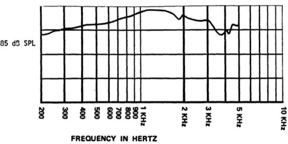
intelligi-bility could be increased. An improved design was developed, resulting in the transferfunction shown in Figure 1-3[32]. This system obviously has better performance than
9More specifically, the intercom system's transfer function has a large peak in the 2500 to 4500 Hz
frequency range. Many of the gear mesh frequencies of the transmission fall into this frequency range, and are thus amplified more than the pilot's speech, which consists primarily (for male speakers) of frequencies below this range.
901 8o co 7c 6u p 100 IU( FREQUENCY (Hz)
Figure 1-2: Transfer Function of Standard CH-47 Interphone System
the standard configuration and thus provides a more intelligible signal, but very few helicopters were upgraded to the improved communication system. This was largely a result of the fact that the current system is adequate, and the upgrade would require modification of the cockpit hardware, costing money10.
1.3.3
Summary of Noise Suppression Capability
Even with the many attempts to reduce the noise in the cockpit, problems remain. The extreme amplitude of the noise, scattered over a large range of frequencies, cre-ates a spectrum that is particularly difficult to attack. Furthermore, most of the previous work intends to attack broadband noise, making small gains at many fre-quencies. While this is adequate for low volume noise, the amplitude of the CH-47D's noise remains high even after subtantial sound treatments, keeping intelligibility low
enough that attempts to use voice recognition systems in helicopters have met with repeated failure[45]. Solutions to these problems seem to lie along two separate paths:
1
oThe upgrade uses a powered microphone, while the CH-47's standard microphone is an un-powered condenser microphone. Thus, upgrading to the new system would require modification or replacement of the current interphone junction box, in order to provide power to the mike.
I
85 d3 SPL
o 0 a coooX X X
N
FREQUENCY IN HERTZ
Figure 1-3: Transfer Function of Improved CH-47 Interphone System
combining previous work to gain the best aspects of different suppression techniques, and finding new approaches tailored to the noise spectra that obtain significant noise reductions in the frequency ranges that cause the largest problems. Combining a linear-response interphone system with a microphone and accelerometer input system would certainly improve the quality of speech over the radio system, and matching ANR techniques with good earcups can provide substantial noise reductions over the entire range of speech. However, this project concentrates on utilizing the charac-teristics of the noise spectra to tailor a noise reduction system to the frequencies of the CH-47's gearbox that are most intrusive. Taking this approach should yield a substantial difference in the signal's unwanted noise power without greatly affecting the desired signal, the pilots' speech. The result is a better signal to noise ratio, critical for thesuccess of voice recognition systems, and better intelligibility for the humans who have to listen to the gear whine picked up by the microphones.
1.4
Proposed Solutions
In order to develop a system that is customized to the sound spectrum of the CH-47D,
knowledge of the spectrum is crucial. If some characteristic of the noise can be
well-defined, then this knowledge can be used to reduce the noise that causes the greatest
problems. The Chinook's noise spectrum has this characteristic, in that the noise
created by the forward transmission is periodic in nature, producing narrowband noise
spikes. However, while this noise is periodic, its frequency does not remain constant,
and a system is needed that can predict or react to changes in the characteristics of
the noise. This can be done with an adaptive filter or similarly adaptive system, and
the technique of cancelling varying periodic interference is known as Adaptive Notch
Filtering, or Adaptive Noise Cancellation (ANC).
1.4.1
Adaptive Noise Cancellation
Many papers have been published exploring techniques of ANC filtering, especially
for the retrieval or cancellation of periodic, sinusoidal signals in a noisy environment.
Widrow[48] described the LMS ANC algorithm and several of its applications to notch
filtering. Also describing the use of this algorithm for notch filtering is Glover[17],
who demonstrated that if the reference sinusoid signals have amplitudes of less than
one, the resultant notch is of narrower bandwidth, and that a sum-of-sinusoids
ap-proach can be used to reduce the required number of reference signals, at the sacrifice
of substantial time-variant noise. Clark[10] expanded the basic LMS to a block LMS
method, in order to take advantage of parallel processing techniques for MIMO LMS
algorithms. The LMS algorithm itself can be greatly simplified if the sampling rate
is an integer multiple of the noise frequencies[11], producing better notch filters with
large reductions in computation time. Goodwin[16] explored the Kalman filter as
an adaptive notch filter, and related its characteristics to the LMS methods. In
situations where the input is not well-characterized and LMS performs poorly, the
Recursive LMS (RLMS) method can be used[13], at the cost of calculation speed. If
low steady state error must be combined with rapid convergence rate, then the
inte-gration constant can be varied over time rather than held constant, called the Variable Step (VS) LMS algorithm[19]. Another option is to utilize the Sequential Regression (SER) method, especially if extremely narrow notches are required[29]. Again, this comes at the cost of higher complexity, especially for MIMO problems. Higher Har-monic Control has been explored by several[18, 36, 37] for elimination of narrowband vibrations, especially as applied to helicopter rotor harmonics. Sievers[38] brought classical control, HHC, LMS, and modern control methods together for comparison in one paper.
1.4.2
Algorithms Examined
There are several DSP algorithms which can be used to implement notch filters with varying center frequencies, three of which were explored in this project. Perhaps the most common approach is to utilize some form of Widrow's Adaptive Noise Cancella-tion (ANC)[3, 12, 13, 17, 31, 33, 48] techniques, most notably the Least-Mean-Squared (LMS) algorithm, which implements a notch filter whose center frequency can be con-trolled by changing the frequencies of the sinusoidal reference inputs. In short, the algorithm uses an integrator to progressively estimate the frequency components of the input signal that are near the reference frequency, and uses a feedback loop to subtract this error from the input signal. If the reference input's frequency is propor-tional to the transmission rotation rate, then the algorithm can be used to cancel the gear mesh frequencies. A second approach, related to this technique, is the Tracking Filter (TF) algorithm[18, 231". This procedure performs the same frequency esti-mation, but uses a lowpass filter and a feed-forward loop to cancel the noise. The third approach is to utilize the frequency normalization that occurs when sampling an analog signal to .control the center frequencies of constant-coefficient filters. In this case, traditional digital notch filters are designed and implemented based on a nom-inal sampling rate, and as the actual sampling rate changes, their center frequencies will change proportionally with that rate. Thus, if the sampling frequency is
pro-"
1 The TF algorithm is a particular implementation of an algorithm more generally known as
portional to the transmission rotation rate, the notches will reduce the signal power in the desired frequency bands. This approach is called the Variable Sampling Rate
(VSR) algorithm. These three algorithms were explored'
2to evaluate their relative
effectiveness in improving speech intelligibility in the helicopter cockpit environment.
1.4.3
Testing Procedures and Results
The algorithms were implemented and tested in several ways. First, the LMS and
TF algorithms were numerically simulated on a computer. This allowed analysis of
their performance under ideal, controllable circumstances, and provided the ability
to explore the effects of non-idealities, such as quantization errors. The simulations
were run with impulse inputs as well as recorded flight data, providing
frequency-domain graphical analyses. These two algorithms were also implemented in 12-bit
forms on a Texas Instrument TMS32020 microprocessor. Unfortunately, its speed
limitations prevented utilization of this chip for more than one or two notch filters.
These two algorithms were also implemented in 14-bit, constant sampling versions
on the Motorola DSP56001, as was the normalized version of the VSR algorithm.
The systems were tested with frequency-response analysis equipment, to compare
to the computer simulation, and several inputs were used to examine the system's
characteristics. Speech was used to explore the system's impact on the intelligibility
of speech with no noise, and cockpit noise recordings were used to determine how
effective the systems were in reducing the transmission's gear whine. Laboratory
tests also explored recordings of the cockpit interphone system as a substitute to
in-flight testing, to determine their effects on the interphone signal.
The LMS and TF algorithms successfully attenuated the selected gear mesh
fre-quencies, and were able to adapt the filter locations as the transmission rotation rate
varied. Both algorithms provided attenuations of 10-35 dB at the selected
frequen-cies, thereby decreasing the noise in the interphone signal. However, they also added
12The LMS and TF algorithms were analyzed fully in a simulation and in real-time hardware.
The VSR algorithm's normalized frequency response was simulated and run in real-time as well, but the variable nature of the algorithm was not implemented.
distortion to the pilots' speech, evident as a noticeable reduction in the speech's fre-quency content, and a ringing sound at the attenuated frequencies. The systems' characteristics were tuned by varying the parameters of the system to provide a good subjective tradeoff between noise reduction and speech degradation. The resultant systems, with equivalent design parameters, were compared using speech, cockpit noise, and the cockpit interphone. The LMS algorithm caused a slightly more no-ticeable ringing, whereas the TF algorithm produced a more nono-ticeable absence of speech frequencies. Subjectively, the ringing was more degrading than the missing frequencies, and the TF algorithm provided slightly better sound quality. Then, to explore the maximum attenuation, notch filters were added to the systems until the computation limits of the processor were reached. The resulting systems provided significant reductions in almost all of the gear mesh noise, but introduced substantial distortion into the speech signal, such that the overall sound quality was reduced. The VSR algorithm was not implemented in real time due to an unforseen hardware limitation, but was run in a frequency-normalized format. The results of this imple-mentation indicate that its characteristics should be very similar to those of the TF algorithm, with substantially reduced computation requirements.
1.5
Reader's Guide to Document
Chapter Two is devoted to characterizing the noise of the helicopter used for this project, the Boeing CH-47D Chinook. It describes the sources of noise, the potential effects of this noise on intelligibility of speech, the way the noise changes over time, and the implications of this variance on the noise reduction algorithms. Chapter Three details the three algorithms used to combat this noise. It explains how the algorithms work, describes practical considerations of the algorithms, and defines the requirements of the reference signal in designing the systems' characteristics. Chapter Four is devoted to the implementation of the algorithms, including data recording, how the algorithms were modelled in computer simulations, and testing procedures. Chapter Five explains the results of the testing, describing how the simulations and
real-time implementations were used to determine the best algorithm design, the results of testing those systems, and recommendations for future work.
Chapter 2
CH-47D Noise Characterization
2.1
General Analysis
The cockpit of the CH-47 is a very noisy environment, due to its proximity to noise sources and its poor sound damping qualities. Noise in the cockpit is reflected off of surfaces such as the windows and instrument panels, and is partially absorbed
by the seats, acoustic blankets, and pilots themselves. Some of the obvious sources
of this noise include noise from the rotors turning overhead, noise from the forward transmission which sits immediately aft and above the pilots, and to a lesser extent, noise from the auxiliary power units and turbine engines at the rear of the helicopter. Modelling the acoustics of such a complex environment is virtually impossible, and analyzing the problem leads instead to collecting experimental measurements of the noise. Boeing has collected a rather exhaustive library of recordings of cockpit noise, and has attempted to determine the sources of this noise as well as the contribution of each source to the total noise. These analyses are presented and built upon in the following section.
2.1.1
Cockpit Noise Spectra
To identify what noise creates the largest problems for pilots and voice recognition systems, it is perhaps best to first identify the frequency range used for speaking.
For this purpose, the frequency range from 200 to 6100 Hz has been broken down
into 20 frequency bands, each of which contributes equally to the intelligibility of
adult male speakers[1]'. These frequency bands are shown in Table 2.1. If each of
these frequency bands supplies an equivalent amount to the understanding of speech,
removing any one of these bands should have the same effect on intelligibility as
removing any other band. This breakdown provides a good start at examining how a
noise spike at a particular frequency affects intelligibility. A noise spike will be defined
as a narrowband (less than approximately five Hz) noise signal of large amplitude;
in the case of the CH-47 interphone system, the noise spike has an magnitude larger
than that of the pilot's voice at the same frequency. By this definition, a noise spike
will dominate the spectrum of the signal at the frequencies where it is present. So,
if a noise spike is present in a larger frequency band (such as that from 5050 to
6100 Hz), it will obscure a smaller percentage of the total frequency band than an
equivalent spike in a smaller band (such as 330 to 430 Hz). Thus, the noise spike in
the larger band will have a smaller effect on the intelligibility of the voice signal that
it is superimposed on. So, reducing a noise spike in a smaller frequency band is more
important than suppressing one in a larger frequency band.
Furthermore, the table denotes a good range of the frequencies that compose male
speech. Defining an upper limit on the necessary frequency range is important,
be-cause a digital system is going to be used. The sampling frequency must be more
than twice the maximum frequency desired because of Nyquist's sampling theorem.
Of course, the higher the sampling frequency, the less time the microprocessor will
have to perform calculations. Furthermore, the input signal will have nonzero
magni-tude at frequencies above the maximum desired frequency, so an analog lowpass filter
must be used to attenuate these frequencies before sampling the signal. This analog
filter will need a finite frequency bandwidth above the highest desired frequency in
order to achieve adequate rolloff at the Nyquist frequency. Based on the idea that the
lower the sampling frequency, the more flexibility will be available in implementing
1A similar breakdown for the adult female would undoubtedly be quite different. However, as
the algorithm on the DSP chip, the sampling frequency should be chosen as small as possible, while allowing for the analog filter and the highest necessary frequency for communication. For instance, if 5000 Hz is chosen as the highest frequency and 3000 Hz is allowed for filter rolloff, we must sample faster than 2(5000 + 3000) = 16 kHz.
This will allow ' = 62.5 ms for calculation, and if the DSP chip has a clock speed
of 5 MHz, then it has an instruction cycle of • = 200 ns. Therefore, with this example, the algorithm on the DSP chip must be performed in less than 62500= 312 cycles, including time for the analog-to-digital (AD) and digital-to-analog (DA) con-versions. If this is not possible, then the sampling frequency must be decreased so that more time is available to perform the necessary computations. Obviously, how-ever, the highest desired frequency must cover most of the range of speech. The range of speech as defined by the military is identical to that of the frequency response of telephones, spanning from 300 to 3000 Hz[26]2. Because the noise reduction system will be designed to maximize intelligibility, it will be designed with a substantially larger range (to at least 6 kHz, the point where the CH-47D interphone begins sub-stantial rolloff) so that more of the important speech frequencies are present, and to enable the system to be transferred to other environments where higher frequencies may be more important (such as for female speakers).
Once the maximum frequency to work with has been identified, the next step is to examine the frequency spectrum of the helicopter cockpit. A typical noise spectrum of the CH-47D cockpit is shown in Figure 2-1. The sampling rate for this graph was 12 kHz, and the spectrum represents a data sample of 2.75 seconds. It is obvious from the diagram that there are several noise peaks that are substantially louder than the rest of the noise. The loudest of these peaks occur at around 1500 and 3400 Hz, although there are substantial peaks near 800, 1200, and 3000 Hz as well. These frequencies all fall within the range of speech, and appear to be narrowband noise (note especially the three distinct peaks near 1450, 1500, and 1600 Hz). Such characteristics make these peaks good candidates for suppression, and closer inspection is warranted. Shown in
2
Note, however, that telephones operate in a largely noise free environment, and intelligibility over phone lines becomes seriously degraded if the background noise exceeds 75 dBA.
All Frequencies are in Hz
Band Frequency Center Band-No. Limits Frequency Width
1 200-300 270 130 2 330-430 380 100 3 430-560 490 130 4 560-700 630 140 5 700-840 770 140 6 840-1000 920 160 7 1000-1150 1070 150 8 1150-1310 1230 160 9 1310-1480 1400 170 10 1480-1660 1570 180 11 1660-1830 1740 170 12 1830-2020 1920 190 13 2020-2240 2130 220 14 2240-2500 2370 260 15 2500-2820 2660 320 16 2820-3200 3000 380 17 3200-3650 3400 450 18 3650-4250 3950 600 19 4250-5050 4650 800 20 5050-6100 5600 1050
Frequency, Hz
Figure 2-1: Frequency Spectrum of CH-47D Cockpit 80 S60 S40 S20 0 1370 1410 1450 1490 1530 Frequency, Hz
Figure 2-2: Close-up of Frequency Spectrum Near 1450 Hz
Figure 2-2 is a closeup of the highest peak in the frequency spectra. It is apparent
in this view that the peak actually consists of several very narrowband noise spikes. These spikes appear to be centered around the peak at 1452 Hz, at roughly ±13.5 Hz,
±27 Hz, ±40.5 Hz, and about ±54 Hz. Because of the even spacing of these spikes,
it is logical to conclude that the peak is actually comprised of a central noise spike and several sidebanded frequencies. All of the spikes have very small bandwidth, on the order of less than 2 Hz. It would therefore seem that removing the signal content at these frequencies could yield a substantial improvement in speech intelligibility.