HAL Id: hal-02380026
https://hal-amu.archives-ouvertes.fr/hal-02380026
Submitted on 26 Nov 2019
HAL is a multi-disciplinary open access
archive for the deposit and dissemination of
sci-entific research documents, whether they are
pub-lished or not. The documents may come from
teaching and research institutions in France or
abroad, or from public or private research centers.
L’archive ouverte pluridisciplinaire HAL, est
destinée au dépôt et à la diffusion de documents
scientifiques de niveau recherche, publiés ou non,
émanant des établissements d’enseignement et de
recherche français ou étrangers, des laboratoires
publics ou privés.
Distributed under a Creative Commons Attribution| 4.0 International License
Negative ion source development for a
photoneutralization based neutral beam system for
future fusion reactors
A. Simonin, R. Agnello, Stéphane Bechu, J. Bernard, C. Blondel, J. Boeuf, D.
Bresteau, Gilles Cartry, W. Chaibi, C. Drag, et al.
To cite this version:
A. Simonin, R. Agnello, Stéphane Bechu, J. Bernard, C. Blondel, et al.. Negative ion source
devel-opment for a photoneutralization based neutral beam system for future fusion reactors. New Journal
of Physics, Institute of Physics: Open Access Journals, 2016, 18 (12), pp.125005.
�10.1088/1367-2630/18/12/125005�. �hal-02380026�
Negative ion source development for a
photoneutralization based neutral beam system for future
fusion reactors
A. Simonin1, R. Agnello2, S. Bechu4, JM. Bernard1, C. Blondel7, JP. Boeuf3, D. Bresteau7, G. Cartry5, W. Chaibi8, C.
Drag7, B. P. Duval2, H.P.L.de Esch1, G. Fubiani3, I. Furno2, C. Grand1, Ph. Guittienne6, A. Howling2, R. Jacquier2,
C. Marini2, I. Morgal5
1CEA, IRFM, F-13108 St Paul lez Durance, France
2Ecole Polytechnique Fédérale de Lausanne (EPFL), Swiss Plasma Center, CH-1015 Lausanne, Switzerland 3Laboratoire Plasma et Conversion d’Energie, LAPLACE, P. Sabatier University, F-Toulouse, France 4LPSC, Université Grenoble-Alpes, CNRS/IN2P3, F-38026 Grenoble France
5 Aix Marseille Univ, CNRS, PIIM, Marseille, France
6Helyssen, Route de la Louche 31, CH-1092 Belmont-sur-Lausanne, Switzerland.
7 Laboratoire Aimé-Cotton (LAC), CNRS, université Paris-Sud, école normale supérieure de Cachan, bât. 505,
F-91405 Orsay cedex
8 ARTEMIS, OCA, CNRS, Université Côte d’Azur, Boulevard de l'Observatoire, F06304 Nice, FRANCE
Abstract: In parallel to the developments dedicated to the ITER neutral beam system, CEA-IRFM with laboratories
in France and Switzerland are studying the feasibility of a new generation of Neutral Beam (NB) system able to provide heating and current drive for the future DEMOnstration fusion reactor (DEMO). For the steady-state scenario, the NB system will have to provide a high neutral beam power level with a high wall-plug efficiency (~60%). Neutralization of the energetic negative ions by photodetachment (so called photoneutralization), if feasible, appears to be the ideal solution to meet these performances, in the sense that it could offer a high beam neutralization rate (> 80%) and a wall-plug efficiency higher than 60%. The main challenge of this new injector concept is the achievement of a very high power photon flux which could be provided by 3 MW Fabry-Perot optical cavities implanted along the 1 MeV D- beam in the neutralizer stage. The beamline topology is tall and narrow to
provide laminar ion beam sheets, which will be entirely illuminated by the intra-cavity photon beams propagating along the vertical axis. The paper describes the present R&D (experiments and modelling) addressing the development of a new ion source concept (Cybele source) which is based on a magnetized plasma column. Parametric studies of the source are performed using Langmuir probes in order to characterize and compare the plasma parameters in the source column with different plasma generators, such as filamented cathodes, radio-frequency driver and a helicon antenna specifically developed at SPC-EPFL satisfying the requirements for the Cybele (axial magnetic field of 10 mT, source operating pressure: 0.3 Pa in hydrogen or deuterium). The paper compares the performances of the three plasma generators. It is shown that the helicon plasma generator is a very promising candidate to provide an intense and uniform negative ion beam sheet.
1.
INTRODUCTIONNeutral Beam (NB) heating systems are required to provide heating and current drive in the future DEMOnstration fusion reactor (DEMO); two different DEMO machines are so far under consideration [1-3]: a pulsed tokamak (DEMO1) with 50 MW D° beam at 1MeV, and, a steady state fusion reactor (DEMO2) requiring more advanced technologies and high neutral power, i.e., ~135 MW of D° beam at 1 or 2 MeV. For DEMO2, maximizing the NB system efficiency (the so-called wall-plug efficiency) becomes a major requirement to minimize both the recirculating electrical power within the plant and the electricity cost; indeed, a tolerable electricity cost produced by a fusion reactor requires a global wall-plug efficiency () ideally higher than 60% [4].
To fill the gap between the present low efficient (< 28%) negative ions based NB devices which rely on collisional neutralization with gas [5], exploration of different beam neutralization processes targeting a higher neutralization rate have been underway over the last decades; indeed, gas neutralization only offers a modest neutralization rate (less than 58% for D- at 1 MeV, with a line density ofl·n= 1.2·1020 m-2 where l is the neutralizer
length, and n the gas density in the neutralizer cell. On the other hand, amongst the constraints experienced in a fusion reactor, the tokamak building dimensions, which strongly impact on the electricity cost, have to be minimized. To do so, the available free space allocated to the NB systems is tight; to comply with it, the neutralizer cell is short (only l=3 m long on ITER), and the amount of gas injected in the neutralizer cell is significant. On ITER, despite large cryo-pumping systems (pumping speed ~5000 m3/s), the background gas density in the accelerator is high, it
leads to 28% of D- losses by stripping [5,6], and several MW of thermal loads on the accelerator grids [7] thus
contributing to a low wall-plug efficiency (< 28%).
2.
NEGATIVE ION NEUTRALIZATION FOR THE NEXT GENERATION OF NEUTRAL BEAM SYSTEMSIn the energy range and neutral power of interest for fusion reactors, different neutralization processes have been investigated such as the mutual beam-beam (D+-D-) neutralization [8], or electron stripping by collisions on
different targets: solid target (foils), heavy gases or metal vapors [9,10], plasma (plasma neutralizer) [11-12], or photons (photoneutralization) [13-15]
It has been shown that D- collisions with heavy nuclei (from helium up to heavier gases (Ne, Ar)) induce an
emittance growth of the neutral beam, and whatever the gas target, the neutralization rate is always lower than 58% [9]). Making use of a transverse supersonic alkali metal vapour jet with lithium (Z = 3) [10] as a ribbon across the ion beam could increase the neutralization rate up to 62% and reduce the gas load (low target thickness: n·l ~0.5·1020
m-2). The lithium vapour jet at high temperature (~1100-1200 K) efficiently condenses on cold metal surface (vapour
pressure: 10-18 Pa at 20°C) limiting its migration along the beamline. Unfortunately, a recent 2D-3D simulation of a
lithium based neutralizer for ITER [16] has highlighted that the lithium ionization and momentum transfer by the 1 MeV D- beam within the neutralizer cell induces a migration of lithium along the beamline.
Much attention and experiments have been devoted to neutralization of high energy negative ions by collisions with plasma electrons (hydrogen plasma neutralizer) [11,12] which potentially could reach 80% of neutralization rate with an electron line density of l·ne ~ 2·1019 m-2, corresponding for an ITER plasma neutralizer
(of 3 m long) to a density of ne ~7·1018 m-3. A low scale experiment [11] has shown that an ITER plasma neutralizer
would necessitate a complex set up based on superconducting coils implanted around the neutralizer cell (under vacuum) to efficiently confine the plasma by a strong magnetic field of B ~1 T. In addition, to attain the required plasma density, 500 kW of microwave plasma heating would be necessary. It is worth to note, that leakage of plasma particles up and downstream of the neutralizer cell would become a significant issue.
It turns out that up to now, these different R&D have not come up with a solution for the future NB systems. In contrast, photoneutralization is a candidate solution presently under R&D for the future fusion reactors; if feasible, it would be the ideal solution in the sense that it could offer at the same time a complete suppression of the gas injection in the neutralizer, a potentially high beam neutralization rate (> 80%) and wall-plug efficiency > 60%, but, the reverse side of the medal are significant technological problems to be solved.
Prior to envisage the development of a real photoneutralizer, a study of the photoneutralization feasibility [14,17,18] has been conducted over the last decade in France via collaborations between CEA and several university laboratories.
3. P
RINCIPLE OF AP
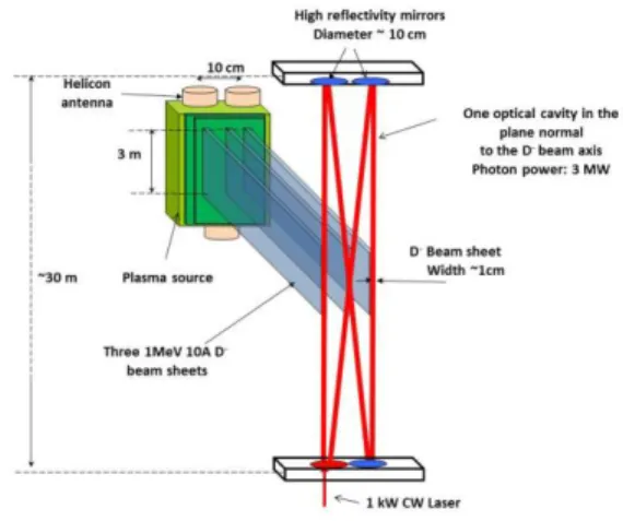
HOTONEUTRALIZATION BASED NEUTRAL BEAM SYSTEMThe low photodetachment cross-section, which ranges between 3.6 and 5·10-21 m2 for = 1064 nm [19, 20],
gives us insight into the way to design both the beamline and its photoneutralizer; indeed, 50% of neutralization rate for a 1 MeV D- beam sheet of 1 cm width requires a photon beam of 3 MW [14, 15, 18].
Past studies have shown [14,17,18] that this high power photon beam could be achieved within a high finesse (10,000) Fabry-Perot optical cavity powered by a 1 kW range CW mono-mode mono-frequency highly stabilized laser.
In parallel, the beamline has to be designed in order to maximize the overlap of the D- beam by
the intra-cavity photon beam; the injector topology will be based on three vertical laminar ion beam sheets of 1 cm width and 3 m height with a kinetic energy of 1 MeV in the photo-detachment area (see Fig.1 and 2). These ion beam sheets are crossed and fully overlapped from top to bottom by the intra-cavity Gaussian TEM(0,0) photon beam propagating
in the plane perpendicular to the ion beams. The photon beam diameter of w = 1 cm (waist) is nearly constant in the interaction region due to a Rayleigh length of zR ~15 m. To comply with these optical
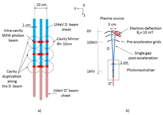
parameters, the cavity is long (cavity roundtrip of 100 m minimum), it is composed of four high reflectivity mirrors (mirror diameter ~10 cm) aligned in the plane perpendicular to the ion beam sheets (see Fig. 1) located far away from the ion beam, about ~15 m above and below from the ion beam. Moreover, to attain a high neutralization rate, several independent identical cavities of 3 MW each can be implanted along the D- beam in the photoneutralizer
region (see Fig. 2-a). The cavity axial dimension along the D- beam (Oz axis) is imposed by the
mirror diameter, = 10 cm. With 50% of
neutralization rate per cavity, the duplication of two adjacent cavities leads to 75% neutralization, or
87.5% with three cavities and so forth. In this configuration, the central ion beam sheet which interacts with the two crossed photon beams (see Fig. 1) will be illuminated by 18 MW of photon power yielding to around 98% of neutralization rate.
Figure 1: Front view: Topology of one cavity; it is a recycling cavity composed with four mirrors aligned in the plane perpendicular to the ion beam; the three D- ion
beam sheet (3m high) cross the 3MW intra-cavity photon beam in the cavity centre. Each D- beam sheet is extracted
from a dense plasma jet produced by Helicon antennas implanted side by side on the source extremities (top and bottom).
This new injector aspect ratio imposes to develop a new type of ion source and accelerator to provide about 10 A of D- per sheet at the relevant D- current density extracted from the plasma source, namely J
D- ~300 A/m2.
Making use of curved extraction grids with slotted apertures in the pre-accelerator stage (from 0 V to 100 kV) followed by a single gap acceleration (post-acceleration) to 1 MeV(see Fig. 2-b), the beam is laterally focussed downstream in the photodetachment region in a thin laminar low divergence (~5 mrad) ion beam of 1 cm width.
A single gap accelerator is proposed with the photoneutralization, because the D- stripping losses are
negligible (less than 1%) in the post-acceleration stage to 1 MeV: there is no need to intercept these electrons on intermediate grids. On the other hand, the co-extracted electrons from the plasma source are deflected out from the ion beam by the vertical magnetic field (Bx ~10 mT) diffusing from the ion source (see paragraph 4.1) and dumped
on the first pre-accelerator grid. It is worth to mention that the pre-accelerator grids do not contain any SmCo permanent magnets.
The 1 MeV non-neutralized fraction of negative ions (D-) can be decelerated at the exit of the
photoneutralizer cell down to a low energy (~50 keV) and collected onto the cooled recovery electrode (see Fig. 3), decreasing in this way the load of the 1 MV power supply. This energy recovery system allows attaining very high injector efficiency even with incomplete photoneutralization. Moreover, the energy recovery system is essential to reduce the power density on the calorimeter surface during the injector conditioning phase to full power; indeed, the
photoneutralizer would operate at a low photoneutralization rate (less than 5% photodetachment), while the energy recovery system would collect the remaining 95% fraction of the negative ion beam current decelerated at a low energy (50 keV). By this way, the thermal load both on the recovery electrode (~9.5 A D- per sheet at 50 keV) and on
the calorimeter (~0.5 A D° per sheet at the high energy 1 MeV) are reduced to an acceptable level, and the power density distribution on the calorimeter surface would provide information on the negative ion beam properties (beam profile and divergence) at the accelerator exit. With the short photoneutralizer length (only 30 cm long, see Fig. 2-a and Fig.3), the additional divergence induced by the 1 MeV D- space charge (~9.5 A D- per sheet) remains limited, it
does not impact on its transport to the recovery electrode.
The nickname “Siphore” of this new injector concept stands for SIngle gap accelerator with PHOtoneutralization and energy REcovery system.
Figure 2: a) Top view: Duplication of three optical independent 3MW cavities along three D- beam sheets. b) Pre
Figure 3: SIPHORE injector concept (Top view of the beamline)
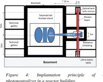
Fig. 4 shows the implantation of a photoneutralizer in a reactor environment; the optical tanks containing the mirrors are located in technical galleries (outside the bioshield) 15 m above and below the injector tank. They are connected to the beam tank by pipes equipped with vacuum pumps to maintain a high vacuum within the optical tanks (pressure of 10-6 Pa);
such high vacuum protects the mirrors from any pollutants coming from the beam tank. These pipes and optical tanks will be housed in a radiation shielding to avoid damages and rapid ageing (by X-rays and neutrons) of the optical components (laser, optical fibres and mirrors).
Figure 4: Implantation principle of a
photoneutralizer in a reactor building.
Active servo loops are combined to tune and lock the external laser frequency and position (Pound-Drever-Hall and Ward methods [22,23]) on the cavity resonance. In addition, to prevent mechanical vibrations of the reactor building and the seismic noise, passive and active mitigation systems will contribute to keep the mirror fine alignments. It is worth to note that, these systems are currently used on Gravitational Wave Detectors (GWD), which have recently proved their maturity with the detection of gravitational waves [24]; the development of a future photoneutralizer for fusion would benefit and make use of these different advanced technologies (optics, laser, mirrors, vibration mitigation, etc.), knowledge and experience gained in the European laboratories working on the GWD: Virgo [25] and GEO600 [26].
The main challenge and specificity of a photoneutralizer for Fusion, is the high power in the cavity which necessitates to control the mirror mechanical deformation induced by the intense CW photon flux (~3 MW over 1 cm diameter); indeed, despite a very low photon absorption rate (~1 ppm 3 W heat load) of the mirror layers, dedicated mirror cooling and compensation systems [14, 22] are required to annihilate the mirror distortion and control its planeity. On the other hand, the cavity has to be fed by a 1 kW range highly stabilized monomode CW laser which does not exist yet. The present laser achievements are significant: several hundreds of watts of single mode and single frequency laser beam have already been demonstrated in a fiber amplifier based system [27, 28], making us confident on the fact that the kW range could be reached using coherent superposition techniques on a few laser beams [29].
4. I
ON SOURCE DEVELOPMENT FORS
IPHOREConventional negative ion sources [30] used for NBI systems are either based on filaments or on radio-frequency (RF) heating. All make use of Cesium to produce sufficient amounts of negative ions. Most RF-based negative-ion sources use Inductively Coupled Plasmas (ICPs) produced by several RF plasma generators, called “drivers”. These are all connected to the common diffusion chamber at the back of the negative ion source [30] and produce a hydrogen or deuterium plasma, which pass through a transverse magnetic field (called filter field) in the diffusion chamber and bombards the first accelerator electrode (the Plasma Grid (PG)). Here, negative ions are formed and extracted
The filter field acts as a magnetic barrier which cools down the hot electrons generated within the drivers and prevents a high destruction rate of the negative ions formed on the PG. The source has to produce high and uniform current density (JD- = 300 A·m-2 of extracted current density with ±10% of homogeneity) over a large area
(plasma grid surface of ~0.8 m2 on ITER) at a low operating pressure (p < 0.3 Pa) to limit the negative ion losses by
stripping reactions in the accelerator.
Past experiments on source prototypes [31] and plasma modelling [32-38] have shown that a diamagnetic plasma drift occurs along the vertical axis leading to significant plasma inhomogeneity (along the vertical axis) in the extraction region; as a consequence, the transverse filter field is not well adapted for the production of a long blade shaped negative ion beam (3 m height, 1 cm width in the photodetachment region), as required by the Siphore injector.
4.1. THE CYBELE SOURCE AT IRFM
The Cybele ion source is a tall and narrow ion source (see Fig. 5-a) with a rectangular aspect ratio that is particularly relevant to study a new source concept for Siphore; its plasma source dimensions are: height 1.2 m, width 15 cm, depth 20 cm. One of the rectangular face of the source is connected to the accelerator and would be used to extract the negative-ions. This face is called hereafter the source front.
During the first stage of the developments, Cybele was a filament plasma source in which 5 sets of 3 tungsten filaments were used as cathodes (Vcathode=-70V) along the source vertical axis. The filaments are introduced in the
source through the back face (see Fig.6). The filaments supply the plasma centre with several hundred amperes of 70 eV primary electrons (Ie-) emitted along the source axis (Ox). Cybele was tested first with a transverse magnetic
filter of 40 mT cm (same magnitude as the ITER source magnetic filter field) on the source front (i.e. at the position of the PG), and the plasma (the primary electrons) was produced by the hot cathodes at the back of the source. These tests have revealed a strong plasma in-homogeneity between the top and the bottom of the source due a diamagnetic plasma drift: at an arc power (Parc= Vcathode * Ie-) of 100 kW, the ion density at the top of the source
was 7 times higher than at the bottom [31].
To overcome the vertical plasma drift, the filter field topology was replaced by a uniform vertical magnetic field parallel to the source vertical axis (Ox), in order to form a vertical magnetized plasma column. The magnetic field is generated by two lateral coils sitting on opposite sides of an iron rectangular frame which surrounds the source (see Fig. 5-a, -b). The two coils generate magnetic fields in the opposite direction inside the iron structure (see Fig. 5-b). It is the leakage field between the two coils that then uniformly fills the plasma source volume.
The magnetic field intensity within the whole plasma volume can be tuned between 0 and 10 mT by adjusting the DC electric current in the coils. In such magnetized plasma column, charged particles are not magnetized identically. For a magnetic field intensity of 7 mT, the Larmor radius of 70 eV primary electrons emitted in the plasma centre is a few mm.
Electrons can move freely around the vertical magnetic field (Bx) lines: they leak at the source extremities
(top and bottom) due to the open magnetic field lines, and make the plasma density along the column axis (Ox) uniform [31]. Perpendicularly to the magnetic field lines (plane Oyz), the electron transport is impeded and occurs mainly due to collisions. In this geometry, density gradients obviously exist, between the centre of the source where heated filamented cathodes are located (see Fig. 6) and the source walls (anode) where ions recombine.
Ions move more slowly than electrons along the magnetic field due to their lower thermal velocity, but their radial diffusion is faster. The fact that ions diffuse preferably radially (towards the extraction region) while electrons escape vertically along the field lines is a rather interesting behavior for a negative ion source which must extract a uniform high negative ion current (in the plane Oxy) along the Ox axis with a low co-extracted electron rate (less than 1e- per D-).
Figure 5: a) Scheme of the RF plasma driver implantation on the top and bottom of Cybele; b) Horizontal cross section of the Cybele source .
Figure 6: Horizontal cross section of the Cybele source; the heated filament (cathodes) supply the source centre with primary electrons. The combination of the density radial gradient (∇𝑛) with
the vertical B-field induced a horizontal plasma rotation (J).
In parallel to experiments, simulation of the Cybele source operation with filaments have been performed at the Laplace laboratory with the PIC MCC (Particle-In-Cell Monte Carlo Collisions) model described in Refs. [39-40]. The PIC MCC model is two-dimensional in the plane perpendicular to the magnetic field. A discharge in pure H2 is
considered and no plasma chemistry is included in the model. A complete set of electron-H2 collision cross-sections,
charge exchange collisions of positive ions, and electron-ion Coulomb collisions are taken into account. Since it is practically impossible, with PIC simulations, to simulate steady state situations with plasma densities as large as 1018
m-3, which are expected in Cybele, smaller plasma densities (on the order of 1015 m-3) and use of a scaling factor
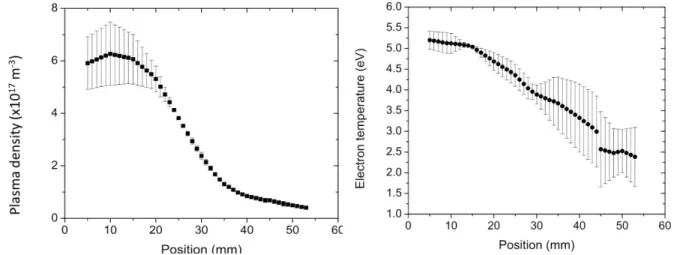
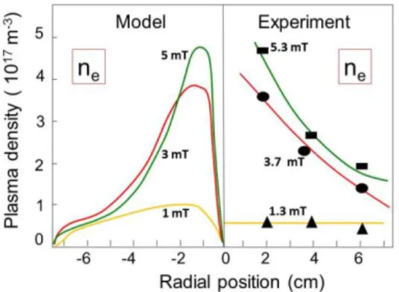
were considered. Experimentally, the radial plasma density, temperature (and potential) distributions have been measured using movable Langmuir probes (see Fig. 6) for different magnetic field intensities at 30 kW of arc power
coupled to the plasma (Parc = Vcathode · Ie-). These profiles (model predictions and experimental results) are shown in
Fig. 7 and 8. At a low magnetic field (low plasma confinement), the plasma density is low (less than 1017 m-3) with a
flat radial distribution (see Fig. 7), while the electron temperature is high and nearly constant (Te ~ 5.5 eV) (see Fig.
8) between the plasma center and the wall.
Figure 7: Radial profile of electron density (ne) at
different magnetic field intensities (1.3, 3.7, 5.3 and 7 mT) with the filamented cathodes with 30 kW of electrical power coupled to the plasma.
left: Model prediction (at Laplace) right: Experiment on Cybele (IRFM)
Figure 8: Radial profile of the electron temperature (Te); same conditions than Fig. 7.
left: Model prediction (at Laplace) right: Experiment on Cybele (IRFM)
At higher magnetic field (B = 5.3 mT), we observe a hot and dense plasma in the centre (ne ~ 5·1017 m-3, Te =
9 eV) with a radial Te cooling towards the source walls. The increase of the plasma density in the source centre is due
to the magnetic confinement of the primary electrons, and most of the ionization takes place in a region of a few cm radius around the filamented cathodes.
The 2D plasma model of the magnetized plasma column developed at Laplace laboratory shows a good qualitative agreement with the experimental results (see Fig. 7 and 8); it highlights the need of a higher magnetic field than 5 mT to lower electron temperature to less than 2 eV in the extraction region of the accelerator. The model also reveals that the density profile does not fit ambipolar diffusion profile with classical diffusion coefficient; by contrast, it predicts that due to the radial density gradient, rotating instabilities are present and contribute to electron transport acrossthe confining magnetic field. Indeed, the radial profile shows that at a low magnetic field (3 mT), the plasma bulk is quasi-equipotential (E = 0V/cm), while a higher magnetic field than 5 mT, a time-averaged radial electric field of about 1 V/cm appears in the plasma. This is consistent with Langmuir probe measurements in Cybele [18].
Further simulations including negative ions (nH- ≈ ne-) generated on the source wall will be performed. The
rotating instabilities may however be less important in the presence of non-negligible densities of negative ions because of the resulting increase in conductivity (ions are much less magnetized than electrons).
4.2. Cybele with an ICP RF plasma generator
Experiments with filamented cathodes discharges have shown that the primary electrons emitted in the plasma center along the source axis undergo a radial cooling. This should allow an effective production of negative ions in the extraction region. However, hot cathodes cannot be used to produce negative ions in the plasma core as the tungsten evaporated by the heated filaments would contaminate the low work function caesiated metal surfaces
(where negative ions are formed) and consequently increase the Cesium consumption. RF plasma generators, ICP or helicon sources, have to be implemented at the extremities of Cybele (top and/or bottom) (see Fig. 5) to inject the plasmas in the direction parallel to the magnetic field lines. The RF generators are immersed in the source vertical magnetic field generated by the surrounding coils (electro-magnet).
An ICP driver at 1 MHz, 10 cm inner diameter, with a solenoid antenna has been installed at the bottom of the Cybele source (see Fig. 5-a). The ICP driver currently operates at 30 kW of active RF power coupled to the plasma at an operating source pressure of 0.3 Pa. Movable Langmuir probes have been used in the source volume above the RF driver to measure the plasma radial parameters (mainly ne and Te) along the x- and radial directions.
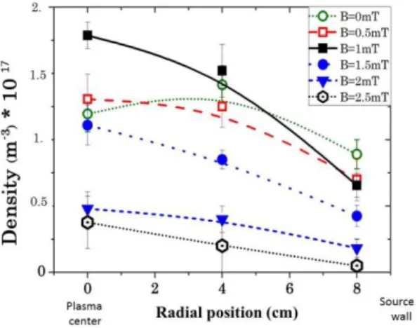
Figure 9 and 10 show the radial profiles of the plasma density and temperature at 15 cm above from the driver exit for different magnetic field intensities (from 0 up to 2.5 mT).
Figure 9: Radial profile of electron density (ne) at
different magnetic field intensities (0 up to 2.5 mT) with a 30 kW ICP RF driver.
Figure 10: Radial profile of effective electron temperature (Te) at different magnetic field intensities
(0 up to 2.5 mT) with a 30kW ICP RF driver.
The DC vertical magnetic field strongly affects the coupling of the RF power above 1 mT. Without magnetic field, the density in the plasma center (radial position = 0 cm) ranges around 1.2·1017 m-3, it increases up to
1.5·1017 m-3 and rapidly drop to less than 1·1017 m-3 for B
x > 1.5 mT. This effect probably comes from the fact that
the primary electrons accelerated by the RF azimuthal electric field (E) experience a radial Lorentz force (v x Bx)
which reduces the transverse plasma conductivity and thus, the induced RF azimuthal current flowing within the plasma. For magnetic fields larger than 2.5 mT, it becomes impossible to couple the RF active power to the plasma. On Fig. 9 and 10, one can also note that the density variation from center to edge is low (ne < 1·1017 m-3) and
temperature radial profile is nearly flat. Furthermore, we observe a rapid decay of the plasma density (along the source axis Ox) with the distance from the driver exit (see Fig. 11), at the source mid-height (60 cm), the plasma density is below the probe resolution.
So far in this section, the experiment of the Cybele source equipped with one 30 kW RF driver has highlighted a strong limitation of the RF wave coupling when the driver is immersed in the axial (vertical) DC magnetic field; the drop of the plasma density with the field intensity or with the distance from the driver exit indicates the inability for such RF plasma generator to supply a long magnetized plasma column as required for the Siphore negative ion source of 3 m height.
Figure 11: Plasma density distribution along the source vertical axis (Ox)
4.3. HELICON PLASMA GENERATOR DEVELOPMENT FOR CYBELE (SPC-EPFL)
SPC laboratory and Helyssen Sarl are developing for Cybele a 10 kW helicon plasma generator operating at 13.56 MHz on the Resonant Antenna Ion Device (RAID) test bed at SPC. Although a single 10 kW helicon generator will probably not achieve the relevant plasma density required for ITER or DEMO (JD- ~300 A/m2), the 10 kW
helicon source is an intermediate step allowing investigation of the main technology and physics issues of high power helicon sources. These include tests with Hydrogen and Deuterium gas at different pressures, magnetic field and RF power levels, spectroscopic measurements of the H/D dissociation rate and Langmuir probe measurements of electron density and temperature profiles.
Figure 12 shows the experimental set up with the main elements; the helicon antenna [41-43] is axially mounted on the right end side of the vacuum chamber. The cylindrical vacuum chamber (diameter 0.4 m, length 1.8 m), is equipped with 6 magnetic coils allowing the generation of an axial magnetic field up to approximately 50 mT that can mimic the magnetic field configuration of Cybele.
Figure 12: The Resonant Antenna Device (RAID) testbed, with the Helicon antenna on the right end side generating a plasma jet in the downstream vacuum chamber.
The helicon antenna, shown on Fig. 13, is based on a resonant network antenna [41-43], also
dubbed birdcage antenna. The RAID device is
equipped with a positioning system allowing for three-dimensional measurements with internal probes (Langmuir and magnetic probes). A spectrometer in the visible range also equips the RAID, which allows for absolute spectroscopic measurements.
Figure 13: Helicon antenna [41-43] which consists of a 9 leg cylindrical resonant network used for helicon excitation.
An experimental campaign was performed with a compensated Langmuir probe in collaboration with LPSC laboratory to measure the radial profile of electron density and temperature along the diffusion. The movable Langmuir probe is installed perpendicularly to the RAID axis at 37 cm away from the helicon antenna in the downstream region. The probe tip is oriented perpendicularly to the magnetic field; hence the drift coefficient defined by Popov et al. [44]
is weak (< 0.3) with respect to 1, the reference value given in [44]. As a consequence, at the measurement locations, the plasma is considered as isotropic, hence the Druyvesteyn relation between second derivative and EEDF [45] is considered as valid. As the electron temperature is higher than 2 eV, in these radial positions, the production of negative ions by dissociative attachment could be neglected. Hence, the sheath edge potential or the Bohm’s criterion does not suffer from negative ions presence in the plasma [46]. Each I(V) curve is the result of the average of three I(V) curves and a curve consists of 200 points averaged over 800 measurements. These measurements have been performed both in Hydrogen and Deuterium under the same working nominal conditions required in the Cybele source, namely 0.3 Pa of pressure and approximately 10 mT of axial magnetic field.
The plasma profiles of the electrons density and temperature are illustrated in Fig. 14 and 15 in the case of a hydrogen plasma and with 3 kW of injected RF power. By comparison with the plasma sources previously tested on Cybele, namely the filamented cathodes and ICP drivers, the magnetized plasma column on Fig. 14 and 15 peaks in the center (r = 0 m) with a hot and dense plasma. This plasma regime enhances the dissociation rate of hydrogen molecules and their excitation to the high ro-vibrational levels; other noticeable advantage is the efficient radial cooling with an electron temperature of less 2 eV (Bx = 100 mT) near the source wall. This behavior is optimal both for the production
of negative ions in volume and on caesiated surfaces. Indeed, the volume production requires the excitation of molecules by hot electrons in the center followed by a dissociative attachment with cold electrons (on these excited molecules) on the edge, while, negative ion production on a surface requires an intense atom flux on the caesiated metal in a cold plasma (Te < 2eV).
Figures 16 & 17 show visible light images of the hydrogen plasma obtained from an end-on view perspective in Cybele with 30 kW RF power coupled in the ICP (Fig. 16) driver and, on Fig. 17, the RAID device with only 3 kW of RF in the helicon source. These figures clearly highlight the advantage of the helicon antenna with respect to the ICP driver for the Siphore ion source: with ten times less input RF power, the helicon generates a dense plasma jet which propagates along the diffusion chamber axis; additional Langmuir probes will be implanted soon along the chamber the measure the axial density profile and uniformity.
By comparison with the other plasma generators, it clearly appears that the Helicon efficiency is impressive: (i) with 30 kW of arc power with filamented cathodes, ne = 4.7·1017 m-3, for Bx = 5 to 7 mT; (ii) with 30 kW of active RF
power coupled in the ICP driver delivered by the 1MHz generator, ne = 1.6·1017 m-3 for Bx = 1 mT, and ne decreases for
higher magnetic fields; and, (iii) with only 3 kW on input RF power in the Helicon, the plasma density at 37 cm away from the antenna attains around 6·1017 m-3.
The next step of experiments at SCP-EPFL is to increase the input RF power up to 10 kW (nominal value for Cybele) , and, in a second time, to measure the negative ion density in the plasma (produced in pure volume without Cesium seeding) by implementing a photodetachment diagnostic developed at LPSC laboratory.
Figure 14 : Radial profile of electron density (ne) at
37 cm away from the helicon antenna with 3 kW RF power in the Helicon
Figure 15: Radial profile of the electron temperature (Te) 37 cm away from the helicon antenna.
Figure 16: Photo of the Plasma (H plasma emission) emitted in the Cybele source with ICP 30 kW driver (no magnetic field).
Figure 17: Photo of the plasma jet (H plasma emission) emitted by the 3 kW Helicon in the cylindrical diffusion chamber of the RAID testbed. Axial magnetic field of ~10 mT.
5. C
ONCLUSION AND PERSPECTIVESThe helicon plasma generator is a very promising candidate for a Siphore type negative ion source for application to a photoneutralization based neutral beam system. The second phase of the developments both on the RAID testbed and on Cybele, will be to characterize the ability of the magnetized plasma column (Bx = 10 mT)
powered by a 10 kW helicon to produce a high negative ion density in the plasma in pure volume production and in a second step with Cesium seeding. Cybele equipped with the 10 kW helicon will be coupled to a 30 keV pre-accelerator (see Fig. 6) with slotted apertures on the DEIS testbed (at IRFM) to provide and a thin blade-like shaped negative ion H- beam which will be diagnosed in complement to the plasma source diagnostics. The experimental
results will be compared to the predictions of the different negative ion extraction numerical models [47-49] under development and benchmark in laboratories.
6. ACKNOWLEDGEMENTS
This work benefited from financial support by the French National Research Agency (Agence Nationale de la Recherche; ANR) in the framework of the project ANR-13-BS04-0016 (Siphore), ANR-13-BS09-0017 (H-Index), by the PACA county in the framework of the project “dossier 2011_11042” (PACA Siphore) and “dossier 2012_10357” (PACA-Ging). This work has been carried out within the framework of the EUROfusion Consortium and has received funding from the Euratom research and training programme 2014-2018 under grant agreement No 633053. The views and opinions expressed herein do not necessarily reflect those of the European Commission.
7.
REFERENCES[1] G. Giruzzi et al.; Nucl. Fusion 55, 073002, 2015.
[2] R. Wenninger et al., “The physics and technology basis entering European system code studies for DEMO”, submitted to Nuclear Fusion [3] T. Franke, et al., “On the Present Status of the EU DEMO H&CD Systems, Technology, Functions and Mix”; poster SP13-63, 26th SOFE conference proceeding, Austin, Texas USA, 2015.
[4] J. Pamela et al.; Fusion Eng. And design 84, pp 194-204, 2009.
[5] RS. Hemsworth et al.; Review of scientific instrument; vol 79, issue 2, pp02C109 - 02C109-5, 2008. [6] G. Fubiani,et al. ; Physical Review Special Topics – Accelerators and beams- 11, 014202, 2008. [7] HPL. De-Esch et al. ; Nucl. Fusion 55, 096001, 2015.
[8] Nathaniel K. Hicks, Alfred Y. Wong; Journal of fusion energy, vol 26, nos ½, 2007. [9] C.J. Anderson et al.; Phys. Rev. A22, 822, 1980.
[10] L.R. Grisham ; Physics of plasmas 14, 102509 ,2007. [11] V.M. Kulygin et al. ; Nuclear Fusion, Vol. 41, No. 4 , 2001. [12] E. Surrey and E. Holmes; AIP Conf. Proc. 1515, 532–540 ,2013.
[13] J.H. Fink, Photodetachment now, Symposium on fusion engineering; Monterey CA 12-16 October,1987. [14] W. Chaibi at al.; AIP conference proceedings, ISBN 978-0-7354-0630-8, p385,2009.
[15] M. Kovari and B. Crowley; Fusion Eng. Des. 85, 745–751, 2010. [16] F. Duré et al.; Chemical Physics 398, 17–26, 2012
[17] D. Fiorucci, J. Feng, M. Pichot, W. Chaibi; AIP Conference Proceedings, ISBN 978-0-7354-1297-2, 050010, 2015. [18] A. Simonin et al.; Nucl. Fusion 55, 123020, 2015.
[19]M. Vandevraye, Ph. Babilotte, C. Drag and Ch. Blondel; Physical Review A 90, 013411, 2014. [20] A.P. O’Connor et al. ; RSI 86, 113306, 2015.
[22] D. Fiorucci; Ph-D thesis ; Nice-Sophia Antipolis University, UFR Science ; Côte d’Azur Observatory, Nice, France; June 2015 [22] R.W.P. Drever, et al. Applied Physics B, 31 :97 105, 1983.
[23] A. J. Mullavey et al. ; Opt. Express 20, 81,2012.
[24] B. P. Abbott et al. (LIGO Scientific Collaboration and Virgo Collaboration); Phys. Rev. Lett. 116, 241103 – Published 15 June 2016. [25] C. Bradaschia et al.; Nucl. Instr. and Meth.in Physics Research A 289:518 525, 1990.
[26] H. Grote and the LIGO Scientific Collaboration; Class. Quantum Grav. 27, p084003, 2010. [27] Theeg et. al. IEEE Photonics Technology Letters, vol. 24, n° 20, 2012.
[28] G. Guiraud, N. Traynor, G. Santarelli; Optics Letters Vol. 41, Issue 17, pp. 4040-4043, 2016. [29] Sheng-wey Chiow et al.; Optics Letters 37, 3861, 2012.
[30] U. Fantz, P. Franzen, W. Krauss, L. Schiesko, C. Wimmer, D. Wunderlich; AIP Conference Proceedings 1655, 040001 (2015); doi: 10.1063/1.4916443.
[31] A. Simonin, L. Christin, H.P.L. De-Esch, R. Futtersack, P. Garibaldi, F. Villecroze; Nucl. Fusion 52, 063003, 2012. [32] G. Hagelaar, G. Fubiani, JP. Boeuf; Plasma Sources Sci. Technol. 20, 015001, 2011.
[33] JP. Bœuf, G.J.M. Hagelaar, P. Sarrailh, G. Fubiani, N. Kohen; Plasma Sources Sci. Technol. 20, 015002, 2011. [34] G. J. M. Hagelaar, N. Oudini ; Plasma Phys. Control. Fusion 53, 124032, 2011.
[35] St Kolev, G.J.M. Hagelaar, G. Fubiani, JP. Boeuf; Plasma Sources Sci. Technol. 21 025002, 2012. [36] G Fubiani, G.J.M. Hagelaar, JP. Bœuf, S. Kolev ; Phys. Plasmas 19 043506, 2012.
[37] JP. Boeuf, B. Chaudhury; PRL111,155005, 2013. [38] G Fubiani, JP. Bœuf ; Phys. Plasmas 20 113511, 2013. [39] G Fubiani, JP. Bœuf ; Phys. Plasmas 21 073512, 2014.
[40] G Fubiani, JP. Bœuf ; Plasma Sources Sci. Technol. 24 055001, 2015.
[41] Ph. Guittienne, E. Chevalier, Ch. Hollenstein, Journal of Applied Physics 98, 083304, 2005. [42] Ch. Hollenstein, Ph Guittienne, A.A. Howling, Plasma Sources Sci. Technol. 22, 055021, 2013. [43] Ph. Guittienne, A. A. Howling, Ch. Hollenstein, ,Phys. Rev. Lett. 111, 125005.30, 2013.
[44] K. P. Tsv, P. Ivanova, M. Dimitrova, J. Kovačič, T. Gyergyek, and M. Čerček, Plasma Sources Science and Technology. 21, 2012. [45] M. J. Druyvesteyn, Z. Phys. 54, 790, 1930.
[46] J. E. Allen, Plasma Sources Science and Technology. 13, 2004. [47] S. Mochalskyy et al.; Nucl. Fusion 55, 033011, 2015.
[48] JP Boeuf, G Fubiani, L. Garrigues, Plasma Sources Sci. Technol. 25 045010, 2016. [49] F. Taccogna et al.; Plasma Sources Sc i. Technol.; 22, 045019, 2013.

![Figure 12 shows the experimental set up with the main elements; the helicon antenna [41-43] is axially mounted on the right end side of the vacuum chamber](https://thumb-eu.123doks.com/thumbv2/123doknet/12967837.377416/11.918.157.768.658.1003/figure-experimental-elements-helicon-antenna-axially-mounted-chamber.webp)
![Figure 13: Helicon antenna [41-43] which consists of a 9 leg cylindrical resonant network used for helicon excitation.](https://thumb-eu.123doks.com/thumbv2/123doknet/12967837.377416/12.918.499.786.161.382/figure-helicon-antenna-consists-cylindrical-resonant-network-excitation.webp)