HAL Id: cea-02339779
https://hal-cea.archives-ouvertes.fr/cea-02339779
Submitted on 5 Nov 2019
HAL is a multi-disciplinary open access
archive for the deposit and dissemination of
sci-entific research documents, whether they are
pub-lished or not. The documents may come from
teaching and research institutions in France or
abroad, or from public or private research centers.
L’archive ouverte pluridisciplinaire HAL, est
destinée au dépôt et à la diffusion de documents
scientifiques de niveau recherche, publiés ou non,
émanant des établissements d’enseignement et de
recherche français ou étrangers, des laboratoires
publics ou privés.
The DEMO Helium Cooled Lithium Lead advanced-plus
Breeding Blanket design improvement and FEM studies
R. Boullon, J. Aubert, G. Aiello, J.-C. Jaboulay, A. Morin
To cite this version:
R. Boullon, J. Aubert, G. Aiello, J.-C. Jaboulay, A. Morin. The DEMO Helium Cooled Lithium
Lead advanced-plus Breeding Blanket design improvement and FEM studies. Fusion Engineering and
Design, Elsevier, 2018, 146 Part B, pp.2026-2030. �10.1016/j.fusengdes.2019.03.092�. �cea-02339779�
_______________________________________________________________________________ author’s email: [email protected]
The DEMO Helium Cooled Lithium Lead “advanced-plus” Breeding
Blanket: design improvement and FEM studies
Rémi BOULLON
a, Julien AUBERT
a, Giacomo AIELLO
a, Jean-Charles JABOULAY
a,
Alexandre MORIN
aaDen - Département de modélisation des systèmes et structures (DM2S), CEA, Université Paris-Saclay, F-91191
Gif-sur-Yvette, France
In the framework of the European “HORIZON 2020” research program, the EUROfusion Consortium develops a design of a fusion demonstrator (DEMO). CEA-Saclay, with the support of Wigner-CR and IPP-CR, is in charge of one of the four Breeding Blanket (BB) concepts investigated in Europe for DEMO: the Helium Cooled Lithium Lead (HCLL) BB. The BB directly surrounding the plasma is a major component ensuring tritium self-sufficiency, shielding against neutrons from D-T plasmas and heat extraction for electricity conversion.
In this article, the equatorial outboard module of the HCLL reference DEMO BB (“advanced-plus” BB) concept is studied regarding thermal and mechanical behavior during normal and accidental conditions that led to modify the design and enhance the performances. A numerical approach based on the Finite Element Method (FEM) is followed. The methodology established, the assumptions done as well as the results obtained in each case are reported and critically analysed, scrutinizing some open issues on this “advanced-plus” reference concept.
Keywords: DEMO, HCLL, Breeding Blanket, thermo-mechanic, Finite Elements, RCC-MRx code
1. Introduction
In DEMO, the Breeding Blanket (BB) is the component surrounding the plasma which has to withstand severe and various operating conditions while insuring tritium self-sufficiency, neutron shielding and coolant temperature range suitable for heat extraction in order to supply a turbine for producing electricity [1]. Thus, this component is one of the most challenging in DEMO.
During the last few years, the HCLL BB design has evolved from a TBM-like concept, based on the HCLL Test Blanket Module for ITER, to a so-called “advanced-plus” concept in order to increase Tritium Breeding Ratio (TBR). This last concept, which is now the reference design for the DEMO HCLL BB, is characterized by the absence of vertical stiffening plates allowing a reduction of steel amount. The thermo-hydraulic scheme and mechanical design of the HCLL BB has been adapted to fulfill design criteria. Previous studies [2] brought out some weak points in the design. For this reason, this paper is particularly focused on the evolution perspectives of the HCLL “advanced-plus” BB design in order to improve the behavior of the structure. Thermal and mechanical Finite Element Method (FEM) calculations performed with ANSYS and Cast3M FEM-qualified codes [3] [4] on the equatorial outboard module are presented and analysed with RCC-MRx nuclear design and construction code [5] during normal and accidental conditions.
2. HCLL ‘advanced-plus’ BB description
2.1 Mechanical design
In the Multi-Module Segment (MMS) configuration, the HCLL BB is composed of several boxes attached to a
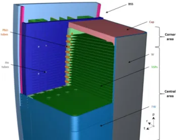
Back Supporting Structure (BSS) which have the same design concept. Fig. 1 presents ¾ of the equatorial outboard module. Helium at 8 MPa is used as coolant with Tin=300°C and Tout=500°C, Eurofer as structural material and PbLi as breeder and neutron multiplier.
The box is formed by a 25 mm thick U-shaped actively cooled First Wall (FW) in front of the plasma, closed on its top and bottom by 75 mm thick actively cooled Caps and on the back by 2 successive 30 mm and 31 mm thick Back Plates (BPs) enclosing a 13 mm thick Helium manifold. The box is reinforced by 41 actively cooled horizontal Stiffening Plates (hSPs) with a thickness of 5 mm in order to withstand the Helium pressure in case of accidental over-pressurization. The dimensions are given in Table 1 and more details of the design are presented in [6].
Fig. 1. HCLL advanced-plus design - ¾ of module isometric view in the (r, t, p) general coordinates
Table 1. General dimensions of the equatorial outboard module Component Parameter Value Unit
Module Poloidal size Toroidale size 1741 1417 mm mm
Tungsten Thickness 2 mm
FW
Poloidal dimention of channel 15 mm Radial (or toroidal) dimension of channel 10 mm Channel rib dimension 5.2 mm Overall FW thickness 25 mm
hSPs + Caps
LiPb poloidal thickness between 2 hSPs 35.4 mm
hSPs pitch 40.4 mm
Poloidal dim. of hSPs and Caps channel 3 mm Toroidal dim. of hSPs and Caps channel 6 mm hSPs and CAPs ribs dimension 8 mm Overall hSPs thickness 5 mm Overall CAPs thickness 75 mm
2.2 Hydraulic scheme
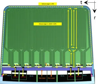
The FW helium channels are the first hydraulic stage (cf. Fig. 2) of the BB module. Helium coolant comes from the BSS at a temperature of 300°C and enters directly into the 86 FW cooling channels of 15*10 mm² after exiting in the Manifold 2. The hSPs & Caps helium channels are the second hydraulic stage (cf. Fig. 2) of the BB module and are cooled in parallel. In its central area, the hSPs are actively cooled thanks to 24 cooling channels per plates of 3*6 mm2 rectangular cross section
each. The Caps are composed of 3 Helium poloidal channel layers per Caps with the same scheme than the hSPs. Helium exits in Manifold 1 and goes out into the BSS.
The 41 hSPs define a poloidal 40.4 mm pitch array allowing the PbLi eutectic breeder flow distribution through the 35.4 mm internal space. The PbLi breeder enters from BSS and is routed to half of the slices in parallel (one slice out of two). PbLi flows between two hSPs frontward (radially), and goes to the slice above through the holes designed one other two on the back of the FW, and then radially flows backwards until it is collected by the BSS.
Fig. 2. Global Helium hydraulic scheme
3. Mechanical calculations in LOCA
A FEM model of a ¼ module has been developed in ANSYS [3]. Its mesh has a quadratic mathematical formulation with 4.9 M nodes and 2.8 M elements.
In case of Loss Of Coolant Accident (LOCA), the box is considered pressurized at P = 10 MPa (cf. [6]).
However, no pressure has been applied on the hSPs upper and lower surfaces due to their equilibrium in case of a LOCA event. Thus, pressure is only applied on the back surface of the FW, the Cap and the BP. Boundary conditions are used in order to make the FEM model consistent with the full geometry of the module thanks to the symmetries: #1 the nodes included in the planes of symmetry are fixed along the direction normal to these ones (i.e. in toroidal and poloidal directions in the design) and #2 displacements of nodes at the back of the box are blocked in the radial direction.
Fig. 3. Von Mises stresses (Pa) in LOCA on a quarter module (deformed x100)
Fig. 4. Stresses linearization scheme in the most stressed area according to RCC-MRx code [5]
Table 2. Stress linearization results (MPa)
Memb. Memb. +Bend. SmD
550°C Pm / SmD Pl / 1.5*SmD Pm+Pb / 1.5*SmD Pm Pm + Pb
Line [MPa] [MPa] [MPa]
1 202.2 278.5 238 0.57 0.78 2 253.0 404.2 238 0.71 1.13 3 370.5 373.4 238 1.56 1.05 4 355.4 588.0 238 1.00 1.65 5 362.9 603.0 238 1.02 1.69 6 97.1 443.0 238 0.41 1.24 7 90.1 126.6 238 0.25 0.35 8 63.7 103.0 238 0.27 0.29 9 266.1 357.8 238 0.75 1.00 10 168.6 211.6 238 0.47 0.59 11 229.8 854.5 238 0.64 2.39 12 413.8 1027.5 238 1.74 2.88 13 325.7 778.0 238 0.91 2.18 14 324.2 757.4 238 0.91 2.12
Regarding the results in LOCA in Fig. 3, in the central area (defined in Fig. 1), the stresses in the FW are relatively reduced comparatively to past models due to the decreasing distance between 2 hSPs which is a clear advantage of the ‘advanced-plus’ model. Some margins
are noticed in the central area, the FW thickness could be reduced locally and/or its shape modified then TBR could raise.
However, some particular areas of the global structure are above the limits fixed by the RCC-MRx as illustrated in the zoom in Fig. 4 and in Table 2 of stress linearization results. The FW structure near the Cap in the corner area (defined in Fig. 1) is locally affected by immediate excessive deformation and immediate plastic instability due to bending effect of the FW near the module corner area: these overstresses are very localized and reached a maximum ratio in membrane plus bending of 2.88 against SmD = 238 MPa (see Table 2 and Fig. 4)
in the corner at the FW back. The area will have to be reinforced.
Moreover, in a Single Module Segment (SMS) configuration, the stresses in the corner area should be reduced by the remoteness of the critical areas and the reduction of the Caps length at the top and bottom of the banana.
4. Thermal calculations in normal condition
Global calculation assumptions have been taken into account and the following hypotheses and boundary conditions have been considered for solving the physical problem: #1 temperature dependent material properties is used for the Helium, PbLi and Eurofer structure in the thermal simulations, #2 the volumetric heat generation deposited inside the steel and PbLi comes from [7], #3 a Heat Flux (HF) of 0.5 MW/m² is considered, #4 the Helium inlet temperature in the FW is 300°C, the outlet temperature from the module is calculated, #5 Helium mass flow rate is calculated to recover the power deposited on the module and plasma Heat Flux (HF) in order to reach a He outlet temperature of 500°C: its value is 4.77 kg/s for the outboard equatorial module, #6 no channels roughness in the channels is considered for the calculations, #7 a Heat Transfer Coefficient (HTC) due to the forced convection with Helium at 8 MPa is calculated for each channels components with the formulas described in Gnielinski equation [8] , #9 proper advection line model is implemented in order to reproduce the thermal effects of the Helium flowing into the cooling channels and #10 thermal coupling between FW outlet advection lines and inlet hSPs advection lines is considered as well as temperature raise in the Manifold.
First, a model of the Cap region and two slices has been developed in Cast3M [4] in order to test various number and position helium channels layers in the Cap thickness. Regarding these results with only 2 helium channels layers, the Cap cannot be cooled enough in the configurations studied and the maximum Eurofer temperature obtained is equal or upper than 594°C. Consequently, 3 helium channels layers in the Cap (cf. Fig. 5) have been implemented for cooling the structure with a 75 mm - thick Cap in a ¼-module model in Cast3M [4]. Its mesh has a linear mathematical formulation with 2.7 M nodes and 13.6 M elements. With this solution (Fig. 5), the temperature of the Cap
reaches a maximum of 556°C which is just above 550°C. The maximum temperature on the Eurofer is now localized on the hSPs and equals 575°C (Fig. 6). The hot spot is always observed in the corner of the elementary hSPs at the end of the second He pass near the FW where the He reached its highest temperature too: this hot spot is localized on small areas. The maximum Eurofer temperature in the FW is 548°C and consequently below 550°C. The thermo-hydraulic results are summarized in Table 3 and Table 4.
Fig. 5. Temperature field in (°C) in the module
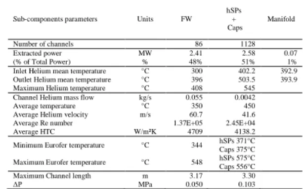
Fig. 6. Temperature (°C) above 550°C in the hSPs Table 3. Sub-components thermo-hydraulic results
Sub-components parameters Units FW
hSPs + Caps Manifold Number of channels 86 1128 Extracted power MW 2.41 2.58 0.07 (% of Total Power) % 48% 51% 1% Inlet Helium mean temperature °C 300 402.2 392.9 Outlet Helium mean temperature °C 396 503.5 393.9 Maximum Helium temperature °C 408 545 Channel Helium mass flow kg/s 0.055 0.0042 Average temperature °C 350 450 Average Helium velocity m/s 60.7 41.6 Average Re number 1.37E+05 2.45E+04 Average HTC W/m²K 4709 4138.2 Minimum Eurofer temperature °C 344 hSPs 371°C Caps 375°C Maximum Eurofer temperature °C 548 hSPs 575°C
Caps 556°C Maximum Channel length m 3.17 3.30
ΔP MPa 0.050 0.103
Table 4. Global thermo-hydraulic results on the module Global parameters Values Units
Equatorial Outboard module
Thermal power to be extracted 5.06 MW Helium mass flow rate 4.77 kg/s Helium ΔT calculated 203.5 °C Total ΔP 0.153 MPa Maximum LiPb Temperature 602 °C Maximum Eurofer Temperature 575 °C Maximum Tungsten temperature 556 °C
5.
Thermo-mechanical calculation in normal
condition
A FEM model of the Cap region and two slices has been developed in Cast3M [4]. This model is reduced compared to the quarter one for calculation time considerations and its mesh has a quadratic mathematical formulation with 4.5 M nodes and 2.9 M elements.
Concerning the loads for the thermomechanical calculation, a representative temperature field of the thermal results (Fig. 6) is applied. Moreover, the mechanical action of the helium inside FW-SW, Caps and hSPs channels is simulated by a pressure of 8 MPa applied on the helium “wetted” surface. Mechanical boundary conditions are imposed to simulate: #1 the symmetry of the model, nodes included in the plans of symmetry are fixed according to the degree of freedom normal of the plans and #2 the BSS influence, nodes at the back of the structure are blocked in the radial direction.
Highest Von Mises equivalent stresses have been calculated under thermomechanical loads (Fig. 7), whereas if only mechanical loads are applied, in this case, low Von Mises equivalent stresses occur within the model and more particularly in the FW. The highest VM stresses are reached in the FW near the Cap. They are due to the dissimilar behavior of the module central area and the corner area which is more massive. Indeed, there is a traction of the FW central area and a compression of the FW in the corner due to thermal field combined with the Cap rigidity. Moreover, high stresses are reached in hSPs due to the thermal expansion of the module in the corner and the effect of pressure in the Helium manifold. Regarding the RCC-MRx A-Level criteria, the criteria are mainly fulfilled for all the channels of the central slices area (i.e. far from the Cap). However, the thermo-mechanical overstresses which have been noticed in the analyses are particularly localized in the FW corner channels in correspondence of the Cap (see red circle on Fig. 7). Immediate plastic flow localizations and ratcheting criteria show stress to limit ratio above 1, respectively equal to 2.06 and 2.09. (Table 5). Note that in this zone, the mesh is gross and could be refined in further study for a better precision of results. Moreover, some previous analyses [9] have shown that in reducing the FW thickness (i.e. less thermal gradient), the values of stresses could be reduced. Moreover, regarding the LOCA analyses, the structure near the last 4 channels in the corner could be reduced insofar this region is not the most significantly stressed and because some margins remain. All the thermo-mechanical results obtained are summarized in Table 5 regarding damages.
Fig. 7. Thermo-mechanical VM equivalent stresses (MPa) in the module corner (deformed x20)
Table 5. Summary of thermo-mechanical results for each damages analysed according to RCC-MRx code [5]
Criteria Immediate plastic collapse and plastic instability Creep damage
Immediate plastic flow localization Ratcheting Fatigue Ratio /Sm Pm Pm+Pb /1.5Sm Pm /St (Pm+Pb) /St (Pm+Qm) /Sem max(Pl+Pb) +∆Q /3Sm Numb. of cycles vs. limit Corner area Respected in each line Respected in each line Respected in each line Respected in each line Some overstresses Some overstresses Respected in each line Central area Respected in each line Respected in each line Respected in each line Respected in each line Respected in each line Respected in each line Respected in each line
6. Conclusions
The results obtained on the ‘advanced-plus’ model are encouraging. Firstly, regarding the LOCA analyses, in the central area, some margins are clearly noticed and the FW thickness could be reduced locally, then TBR could raise: further investigations are needed in order to validate this aspect. Then, concerning the thermo-hydraulic analyses, the total pressure drops for the FW+hSPs+Cap are 0.153 MPa and the temperature reaches a maximum of 575°C locally in hSPs. Finally, regarding the thermomechanical analyses in normal condition, the RCC-MRx criteria are respected regarding immediate plastic collapse and plastic instability, creep and fatigue for all the module structure. Only in the corner area, slight overruns remain at the FW-Caps connection concerning immediate plastic flow localization and ratcheting: evolutions for dealing with these local overruns are provided in this article.
Acknowledgments
This work has been carried out within the framework of the EUROfusion Consortium and has received funding from the Euratom research and training programme 2014-2018 under grant agreement No 633053. The views and opinions expressed herein do not necessarily reflect those of the European Commission.
References
[1] Fusion Electricity – A roadmap to the realization of fusion energy, F. Romanelli et al. EFDA, 2012.
[2] R. BOULLON et al., Investigation on the ‘Advanced-plus’ Helium Cooled Lithium Lead Breeding Blanket design concept for TBR enhancement regarding thermal and mechanical behavior, In press (2018)
[3] ANSYS v17.2 https://www.ansys.com/fr-fr
[4] Cast3M 2017 http://www-cast3m.cea.fr/
[5] RCC-MRx, Design and Construction Rules for Mechanical Components of Nuclear Installations, AFCEN, 2013.
[6] J. AUBERT et al., Report on Deliverable DDD 2017 for HCLL, WPBB‐DEL‐BB‐2.1.2‐T006‐D001
[7] J-C. JABOULAY et al., Nuclear Analysis of the HCLL “Advanced-plus” Breeding Blanket, Fusion Engineering and Design , In press (2018)
[8] V. GNIELINSKI, New equations for heat and mass transfer in turbulent pipe and channel flow, International Chemical Engineering, Vol. 16, No.2, pp. 359-368 (1976) [9] J. AUBERT et al., Thermo-mechanical analyses and ways of optimization of the helium cooled DEMO First Wall under RCC-MRx rules, Fusion Engineering and Design, Volume 124, November 2017, Pages 473-477
![Table 5. Summary of thermo-mechanical results for each damages analysed according to RCC-MRx code [5]](https://thumb-eu.123doks.com/thumbv2/123doknet/12955384.376287/5.892.458.821.407.516/table-summary-thermo-mechanical-results-damages-analysed-according.webp)
