HAL Id: hal-00533708
https://hal.archives-ouvertes.fr/hal-00533708
Submitted on 14 May 2021
HAL is a multi-disciplinary open access
archive for the deposit and dissemination of
sci-entific research documents, whether they are
pub-lished or not. The documents may come from
teaching and research institutions in France or
abroad, or from public or private research centers.
L’archive ouverte pluridisciplinaire HAL, est
destinée au dépôt et à la diffusion de documents
scientifiques de niveau recherche, publiés ou non,
émanant des établissements d’enseignement et de
recherche français ou étrangers, des laboratoires
publics ou privés.
Mode conversion in High overtone Bulk Acoustic wave
Resonators
M. Pijolat, D. Mercier, A. Reinhardt, E. Defaÿ, C. Deguet, M. Aïd, J.S.
Moulet, B. Ghyselen, S. Ballandras
To cite this version:
M. Pijolat, D. Mercier, A. Reinhardt, E. Defaÿ, C. Deguet, et al.. Mode conversion in High
over-tone Bulk Acoustic wave Resonators. Joint Meeting of the 23rd European Frequency and Time
Forum/IEEE International Frequency Control Symposium, Apr 2009, Besançon, France. pp.290-294,
�10.1109/FREQ.2009.5168188�. �hal-00533708�
Mode conversion in High overtone
Bulk Acoustic wave Resonators
M. Pijolat, D. Mercier, A. Reinhardt, E. Defaÿ,
C. Deguet, M. Aïd
CEA, LETI, MINATEC Grenoble, France
J.S. Moulet, B. Ghyselen
Silicon-on-Insulator Technologies SOITEC Crolles, FranceS. Ballandras
FEMTO-ST UMR CNRS-UFC-ENSMM-UTBM 6174 Besançon, France
Abstract— High overtone Bulk Acoustic Resonators (HBAR) have been realized using the Smart Cut™ technology to transfer a thin X-cut LiNbO3 layer onto an X-cut LiNbO3 substrate.
When the bonding of the two wafers is performed, an additional rotation along the normal axis is set to generate mode conversion between the two acoustic shear waves electromechanically coupled in X-cut LiNbO3. This enables
excitation of only one of the two acoustic shear waves. I. INTRODUCTION
As the demand for frequency sources or filters for embedded communication systems is still increasing, High Overtone Bulk Acoustic Resonators (HBAR) are considered as solutions for applications requiring very high quality factors - tens of thousands - at GigaHertz frequencies. Among Very Large Scale Integration devices, rare are those able to face such specifications. The state of the art of Quality factor versus frequency is still hold by Lakin et al. [1] with a maximum of 1.1.1014 obtained with a thin Aluminum Nitride film on top of a 650 microns thick sapphire substrate. More recently, Lithium Niobate (LiNbO3) has been investigated as
single crystal layers on top of several substrates. Gachon et al. [2] have obtained 8.1.1013 with grinded Y+36 Lithium Niobate films down to 30 microns bonded via a thin gold layer on a Lithium niobate wafer and 5.2.1013 with the same process but on a sapphire substrate. On a similar structure we present in this paper - with a different purpose - we obtained 7.9.1013 on HBAR realized thanks to the Smart Cut™ technology applied to piezoelectric layers. 3 inches sub-micron thick X-cut lithium niobate layers were successfully transferred onto lithium niobate wafers [3,4].
Thin piezoelectric layers are easily obtainable from standard microelectronic deposition techniques. However, for Bulk Acoustic Wave resonators for example, sputtered AlN layers are widely known to be non single crystal. Layer
transfer techniques such as grinding polishing or Smart Cut™ technology preserve the integrity of the single crystal materials [5,6,7]. As those layers are both used as transducers and propagating medium, the quality of the thin film has a major impact on performances. One illustration is a band pass filter where a higher quality factor will lead to steeper skirts and thus to easier specifications matching.
Furthermore, the possibility of choosing crystalline orientations of the thin layer is a tremendous advantage compared to deposition techniques. Although AlN grows easily along the c-axis, extreme difficulty appears when one wants growth along a more interesting orientation [8,9]. This extra degree of freedom allows temperature compensated orientations, improved electromechanical coupling factor or the choice for shear or longitudinal waves propagating in the device.
In this paper, we describe a method to convert the two shear waves piezoelectrically coupled in X-cut lithium niobate into a single one. The way is an additional rotation performed when the two wafers are bonded together. The resulting device presents a misalignment between the in-plane axis of the piezoelectric thin layer and of the substrate and hence a mode conversion between the two shear waves occurs. A single wave propagating into the substrate might be obtained while choosing the proper angle.
As a beginning, X-cut Lithium Niobate HBAR devices will be introduced, followed by the experimental process focusing on the Smart Cut™ approach and the additional rotation set for the mode conversion. Finally RF characterizations as well as simulations will be presented to demonstrate the conversion of the shear waves in this device.
Sponsors:
* Substrates were developed in the frame of the CEA-SOITEC joined program.
* This work has been performed with the help of the “Plateforme technologique amont” de Grenoble, with the financial support of the “Nanosciences aux limites de la Nanoélectronique” Foundation.
II. HIGH OVERTONE BULK ACOUSTIC RESONATORS
A. HBAR devices
For filtering applications, Surface Acoustic Wave resonators (SAW), Film Bulk Acoustic Resonators (FBAR) and Solidly Mounted Resonators (SMR) are the three main kinds of acoustic based devices. SAW resonators are opposed to FBAR and SMR as the acoustic wave generated by an InterDigitated Transducer (IDT) is propagating along the surface of the piezoelectric layer. For FBAR and SMR, a “sandwich” of metal – piezoelectric layer – metal is generating the acoustic waves propagating in the bulk of the piezoelectric layer. For FBAR and SMR, when considering only the piezoelectric layer, mechanical resonances exist when half a wavelength of the acoustic wave is an odd multiple of the piezoelectric thickness.
How works a High overtone Bulk Acoustic Resonators (HBAR) is slightly more difficult to understand as it includes, beyond the traditional “sandwich” metal / piezoelectric / metal, a substrate with a much larger thickness (fig.1). An HBAR device is hence divided into two different parts:
• The metal-piezoelectric layer-metal stack is the transducer and converts the electrical signal into a mechanical acoustic wave.
• The substrate is the main acoustic wave propagation medium and mechanical resonances are observed when the substrate thickness is a multiple of half a wavelength.
Electrodes LiNbO3Thin film
LiNbO3Substrate Propagating
acoustic wave
Electrodes LiNbO3Thin film
LiNbO3Substrate Propagating
acoustic wave
Figure 1. High Overtone Bulk Acoustic Wave Resonator (HBAR) principal with LiNbO3 thin film and substrate.
As the first harmonic of an HBAR approaches tens of MegaHertz, RF characterizations at gigahertz range give an outlook of higher order overtones of the first resonance. Furthermore, these high order overtones are modulated by the response of the thin piezoelectric layer. Indeed such a modulation is corresponding to the behavior that the thin piezoelectric layer would have if the effect of the substrate were decoupled. From the corresponding envelop one can extract an approached value of the electromechanical coupling factor of that layer.
B. X-cut LiNbO3
Bulk lithium niobate has been largely investigated for SAW devices. A large number of 3 inches and now 4 inches single crystal wafers are produced for the filters or resonators industry. Its large electromechanical coupling factors contributed to its success. For BAW purposes, X-cut lithium niobate is still really interesting to study owing to its two electromechanically largely coupled acoustic shear waves.
Although the fastest one (4000 m.s-1) is already largely coupled (kt² = 20%) compared to traditional AlN (kt² = 7%), the slowest one (3600 m.s-1) reaches a theoretical maximum value of kt² = 45%. For a resonant frequency above the GigaHertz, thickness of X-cut lithium niobate has to be below 1 micron.
III. EXPERIMENTAL PROCESS
A. Smart Cut™ process applied to piezoelectric media
Obtaining thin layers of single crystal piezoelectric materials is a real challenge. Previous work shows examples of LiNbO3 reported via Smart Cut™ technology [10].
However, such work was focused on Surface Acoustic Wave devices. For BAW resonators, a similar technique can be employed comprising an extra metallic layer which will be used as the bottom electrode (fig.2). Although it was only on a 1cm² sample, efficiency of such technique has already been proved with a thin LiNbO3 layer/Ag layer/Si wafer by Diest et
al.[11].
In our paper, a full 3” transfer has been obtained using Smart Cut™ technology, including an embedded metallic electrode. The process flow used for the fabrication of our devices is as follows:
• A stack comprising metallic electrode and silicon dioxide is deposited on donor wafer ‘D’
• Helium ions are implanted on the donor wafer ‘D’ thus creating an implanted zone at a defined depth. • Molecular bonding is achieved between the donor
wafer and a handle wafer with a silicon dioxide layer. The bonding is followed by the splitting occurring at the implanted depth.
• Chemical Mechanical Polishing may then be used in order to remove the damaged top LiNbO3 layer,
recover a roughness comparable to starting material and adjust the thickness of transferred layer.
• Finally, platinum is deposited by evaporation and etched with an Argon-assisted Ionic Beam milling Etching (IBE) technique to pattern the top electrode.
H D D H H D H + D ¾Metal + oxide deposition and ion implantation ¾Splitting ¾Wafer bonding ¾Top electrodes deposition and patterning H H D D D H H D D H H D H + D H + D ¾Metal + oxide deposition and ion implantation ¾Splitting ¾Wafer bonding ¾Top electrodes deposition and patterning
Successful transfer of 3 inches single crystal X-cut LiNbO3
layer of 800 nm thick was achieved (fig. 3.a). High Resolution TEM (fig. 3.b) images as well as XRD measurements were proofs to demonstrate the single crystal quality of the transferred layer [4].
Figure 3. (a) Full 3 inches LiNbO3 800nm layer transfer. (b) HRTEM of LiNbO3 transferred layer, no extended defects is seen.
B. Additional rotation for mode conversion
This step occurs during the molecular bonding which is performed with a handling wafer with X direction upwards and a donor wafer with X direction downwards. Then the alignment of the in plane axis of the two wafers is realized. Usually, effort is made to align the in plane axis of the donor wafer with the corresponding one of the handling substrate. A rotation along the normal axis (X axis for the X-cut) when the bonding is achieved will have consequences on the device and how acoustic waves propagate. In this paper we intentionally exploit this misalignment in order to convert acoustic waves (fig. 4). Donor wafer
yG
yG
yGyG
zGzG
zGzG
Handling wafer Wafer bonding Additional rotationFigure 4. Additional rotation along the normal axis of wafers during the molecular bonding.
C. RF measurements
Samples were characterized using a two port electrode design via a Vector Network Analyzer HP 8753ES and SOLT calibration. Room temperature characterizations were performed between 1942 MHz and 1958 MHz to focus only on four resonances of the HBAR.
IV. MODE CONVERSION
The aim is to exploit the two shear waves and to demonstrate the possibility of mode conversion.
A. Principal
When the RF voltage is applied, the metal / piezo / metal stack is transducing the electrical signal into mechanical deformations.
• First, the acoustic waves created in the X-cut LiNbO3
are two shear waves as explained previously. Analogy with electromagnetic waves has been demonstrated in previous work [12,13] and those two shear waves can be compared to a polarized EM wave.
• Below the thin LiNbO3 piezoelectric layer, the
amorphous materials have no influence on the polarization.
• Finally, the acoustic wave reaches the LiNbO3 wafer
which is an anisotropic media. Mode conversion between the two shear waves occurs because of the rotation between the axis of the thin layer and the axis of the substrate. Such a conversion is analogous to a polarizer mechanism for electromagnetic waves: polarization changes from elliptical (the two shear waves are excited with different amplitudes) to circular (the two shear waves are excited with the same amplitude) or linear (only one shear wave is excited).
Due to the large thickness ratio between the substrate and the thin lithium niobate layer, the measured impedance, focused on overtones of the HBAR, reveals mainly the behavior of acoustic waves propagating into the substrate. Thus from the elliptical polarization of two shear waves it is possible for HBAR to obtain a single shear wave i.e. a linear polarization.
B. Simulations approach
The concept of mode conversion is validated with acoustic simulations based on the scattering matrix method [14]. From material constants [15], crystalline orientations and thicknesses of the constitutive layers of the HBAR, mode conversion can be demonstrated. Fig.5 shows the real part of admittance of the HBAR for several angles of the additional rotation:
• 0° rotation is the standard where two shear waves propagate along the X axis in X-cut LiNbO3 , causing
an elliptical polarization.
• -20° rotation exhibits the total conversion of the two shear waves into a single one: the fast shear wave, which corresponds to a linear polarization.
• +22° rotation is the angle enabling a circular polarization: the two shear waves have similar amplitudes.
• +70° enables mode conversion of the two shear waves into the slow shear wave.
10 nm
1948,0 1948,5 1949,0 1949,5 1950,0 1950,5 0,00 0,09 0,18 Re al ( Y ) Frequency (MHz) No rotation Rotation of -20° Rotation of +22° Rotation of +70°
Figure 5. Evolution of the behavior of the two shear waves with the angle of rotation.
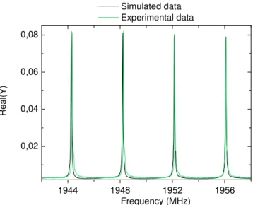
Simulations were also performed to fit RF measurements exposed in the next part. Real parts (fig.6 and fig.7) exhibit perfect matching between measured and simulated data.
C. Characterization
Fig.6 and fig.7 show both experimental data and simulations of the real part of impedance versus frequency. HBAR with no additional rotation is shown on fig.6 and exhibits the two shear waves piezoelectrically coupled in X-cut lithium niobate. The polarizing effect of the additional rotation is then experimentally demonstrated on fig.7 where the slow shear wave is the last one propagating into the substrate. 1944 1948 1952 1956 0,00 0,05 0,10 0,15 0,20 Real (Y ) Frequency (MHz) Simulated data Experimental data
Figure 6. Both shear waves are propagating without the additional rotation.
1944 1948 1952 1956 0,02 0,04 0,06 0,08 Real(Y) Frequency (MHz) Simulated data Experimental data
Figure 7. Mode conversion of the two shear waves into a single one when the additional rotation is set.
V. CONCLUSION
Mode conversion in High overtone Bulk Acoustic Wave Resonators has been demonstrated by simulations and proven by RF measurements. Layer transfer appears to be a real advantage as single crystal is employed and the orientations can be chosen. Nature of the acoustic waves, temperature compensated cuts, coupling factors and here mode conversion are extra possibilities which are not accessible to deposited layers.
REFERENCES
[1] K.M. Lakin, G.R. Kline, K.T. McCarron, “High-Q microwave acoustic
resonators and filters”, IEEE transactions on microwave theory and techniques, Vol.41, n°12, 1993, pp. 2139-2146.
[2] D. Gachon, E. Courjon, J. Masson, V. Petrini, J.Y. Rauch, S. Ballandras, “LiNbO3-LiNbO3 High Overtone Bulk Acoustic Resonator
Exhibiting High Q.f Product”, IEEE International Frequency Control Symposium, 2007, pp. 1143-1146
[3] M. Pijolat, J.S. Moulet, A. Reinhardt, E. Defaÿ, C. Deguet, D. Gachon, B. Ghyselen, M. Aïd, S. Ballandras, “Large Qxf Product for HBAR
using Smart Cut ™ transfer of LiNbO3 thin layers onto LiNbO3
substrate”, IEEE ultrasonics symposium, 2008
[4] J.S. Moulet, M. Pijolat, J. Dechamp, F. Mazen, A. Tauzin, F. Rieutord, A. Reinhardt, E. Defaÿ, C. Deguet, B. Ghyselen, L. Clavelier, M. Aïd, S. Ballandras, C. Mazuré, “High piezoelectric properties in LiNbO3
transferred layer by the Smart CutTM technology for ultra wide band
BAW filter applications”, IEEE IEDM, 2008
[5] S.H. Christiansen, R. Singh, U. Gösele “Wafer Direct Bonding: From
Advanced Substrate Engineering to Future Applications in Micro/Nanoelectronics”, Proc. of the IEEE, Vol.94 , n°12, 2006, pp.2060-2106
[6] M. Bruel, B. Aspar, B. Charlet, C. Maleville, T. Poumeyrol, A. Soubie, AJ. Auberton-Herve, J.M. Lamure, T. Barge, F. Metral, S. Trucchi,
““Smart cut”: a promising new SOI material technology”, IEEE SOI Conference, 1995, pp. 178-179
[7] B. Aspar, H. Moriceau, E. Jalaguier, C. Lagahe, A. Soubie, B. Biasse, A.M. Papon, A. Claverie, J. Grisolia, G. Benassayag, F. Letertre, O. Rayssac, T. Barge, C. Maleville, and B. Ghyselen, “The generic nature
of the Smart-Cut process for thin film transfer”, Journal of Electronic Materials, Vol. 30, n°7, 2001, pp. 834-840
[8] F. Martin, M.E. Jan, S. Rey-Mermet, B. Belgacem, D. Su, M. Cantoni, P. Muralt, “Shear Mode Coupling and Tilted Grain Growth of AlN Thin
Films in BAW Resonators” IEEE Transactions on Ultrasonics, Ferroelectrics and Frequency Control, Vol. 53, n°7, 2006, pp. 1339-1343
[9] C.J. Chung, Y.C. Chen, C.C. Cheng, K.S. Kao, “An improvement of
tilted AlN for shear and longitudinal acoustic wave”, Appl. Phys. A, Vol. 94, n°2, pp. 307-313
[10] T. Pastureaud, M. Solal, B. Biasse, B. Aspar, J-B. Briot, W. Daniau, W. Steichen, R. Lardat, V. Laude, A. Laens, J.-M. Friedt, S. Ballandras,
“High-frequency surface acoustic waves excited on thin-oriented LiNbO3 single-crystal layers transferred onto silicon”, IEEE
Transactions on Ultrasonics, Ferroelectrics and Frequency Control, Vol. 54, n°4, 2007, pp. 870-876
[11] K. Diest, M.J. Archer, J.A. Dionne, YB. Park, M.J. Czubakowski, H.A. Atwater “Silver diffusion bonding and layer transfer of lithium niobate
to silicon”; Appl. Phys. Lett., Vol. 93, 2008
[12] J.M. Carcione, F. Cavallini, “On the acoustic-electromagnetic
analogy”, Wave motion, Vol. 21, n° 2, 1995, pp. 149-162
[13] J.M. Carcione, K. Helbig, “Elastic medium equivalent to Fresnel's
double-refraction crystal” Journ. Of the Acoust. Soc. Of america, Vol. 124, n°4, 2008, pp. 2053-2060
[14] A. Reinhardt, Th Pastureaud, V. Laude, S. Ballandras, “Scattering
matrix method for acoustic waves in piezoelectric, fluid, and metallic multilayers”, J. Appl. Phys., Vol. 94, 2003, pp. 6923-6931
[15] G. Kovacs, M. Anhorn, H.E. Engan, G. Visintini and C.C.W. Ruppel,
“Improved Material Constants for LiNbO3 and LiTaO3”, IEEE ultrasonics symposium, 1990, pp. 435-438