REGIONAL ANAESTHESIA
Ultrasound-guided thoracic paravertebral puncture and
placement of catheters in human cadavers: where do
catheters go?
†C. Luyet
1, G. Herrmann
2, S. Ross
3, A. Vogt
1*, R. Greif
1, B. Moriggl
4and U. Eichenberger
11University Department of Anaesthesiology and Pain Therapy, University Hospital and University of Bern, Bern, Switzerland 2
Institute of Anatomy and3Centre for Forensic Imaging and Virtopsy, Institute of Forensic Medicine, University of Bern, Bern, Switzerland
4Division of Clinical and Functional Anatomy, Department of Anatomy, Histology and Embryology, Innsbruck Medical University, Innsbruck,
Austria
* Corresponding author. E-mail: andreas.vogt@insel.ch
Editor’s key points
† It is often difficult to place a catheter reliably and accurately into the paravertebral space (PVS). † Accuracy of a modified approach to the PVS using loss-of-resistance and ultrasound-guided techniques was examined. † Ultrasound-guided interventions yielded 94% correct needle tip placements but only a few adequate catheter tip positions.
† This may be improved by modifying the design of the catheters.
Background.Paravertebral regional anaesthesia is used to treat pain after several surgical procedures. This study aimed to improve on our first published ultrasound-guided approach to the paravertebral space (PVS) and to investigate a possible discrepancy between the needle, catheter, and contrast dye position.
Methods. In 10 cadavers, we conducted 26 ultrasound-guided paravertebral approaches combined with loss of resistance (LOR) and after an interim analysis performed 36 novel, pure ultrasound-guided (PUSG) paravertebral approaches. Needle-tip position was controlled by a first computed tomography (CT) scan. After placement of the catheters, the tips were assessed by a second CT and the spread of injected contrast dye was assessed by further CT scans. The part of the PVS near the intervertebral foramen was defined as the primary target to reach.
Results.The first CT scans assessing 62 needle tips revealed that: 13 (50%) of LOR and 34 (94%) of PUSG approaches were at the target; and two (8%) LOR and no PUSG approaches were outside the PVS. With the second CT scans 60 catheter-tip positions were analysed: three (12%) of LOR and five (14%) of PUSG approaches were at the target, three (12%) of LOR and two (6%) of PUSG approaches were outside the PVS. No catheters were detected in the epidural space. In two cases, insertion of the catheter was not possible. In cases with major epidural contrast, the widest contrast dye spread was 7.7 (3.5) [mean (SD)]
vertebral segments.
Conclusions. Our new PUSG technique has a high success rate for paravertebral needle placement. Although needles were correctly positioned, catheters were usually found distant from the needle-tip position.
Keywords: anatomy, regional; intercostal nerves; regional anaesthesia, paravertebral; tomography, X-ray computed; ultrasonography
Accepted for publication: 23 September 2010
Paravertebral block is a regional anaesthetic technique which can be used for analgesia after thoracic,1–4cardiac,5 breast,6–8 upper abdominal surgery,9 or for pain therapy.10 The thoracic paravertebral block is performed by injecting local anaesthetic solution into the paravertebral space (PVS), which contains the thoracic nerves, their branches, and the sympathetic trunk. This wedge-shaped space is located between the heads and necks of the ribs. The posterior wall is formed by the superior costo-transverse ligament, the
antero-lateral wall is formed by the parietal pleura with the endothor-acic fascia, and the medial wall is formed by the lateral surface of the vertebral body and the disc. Medially, the PVS communi-cates with the epidural space via the intervertebral foramen, anteriorly with the mediastinum and laterally with the inter-costal space. It has been shown that each space communi-cates inferiorly and superiorly with the next space anterior to the heads and necks of the ribs,11–14allowing local anaesthetic to spread and block more than one intercostal nerve.
Our first cadaver study demonstrated the practicability and accuracy of an ultrasound-guided approach to the PVS. Unfortunately, the subsequent catheter placement resulted in frequent misplacement of catheters into the epidural space or towards the prevertebral region.15The most prob-able cause of misplaced catheters was either due to the needle direction (pointing towards the midline) or due to over-threading of the catheters through the needle (5 cm in this first study). The subsequent use of the new method in our clinical practice was associated with the same unreli-able catheter placement and difficulties for trainees and novices in ultrasound to perform the technique reliably.
The aim of the second anatomical study was to improve our ultrasound-guided approach to the PVS by using a more orthogonal needle orientation. Furthermore, we newly detected the relationship between the needle-tip position – catheter-tip position and the contrast dye spread injected through the catheter by four independent computed tom-ography (CT) scans.
Methods
Ten cadavers in legal custody of the Institute of Anatomy, University of Bern, Switzerland, were studied with
institutional approval for this procedure. The cadavers were embalmed using the method described by Thiel.16 The study was performed according to the ethical guidelines of the Swiss Academy of Medical Sciences for investigations using human cadavers.17
All ultrasound-guided procedures were performed using a portable ultrasound machine (M-TurboTM, Sonosite, Bothell,
WA, USA) with a 2 –5 MHz curved array transducer. In all 10 cadavers, we punctured the PVS at least three times at each side of the thoracic vertebral column (thoracic levels between TH 2 and TH 11) with a minimal distance between the puncture sites of three segments. The punctures were performed using an 18 G Tuohy needle. A catheter was placed subsequently into the PVS (epidural catheter set, B. Braun, Melsungen, Germany) as described later. The cada-vers were placed in the prone position on the CT table with a cushion under the chest to achieve kyphosis. This position allowed the needle placement and subsequent CT scans to be performed without moving the cadaver.
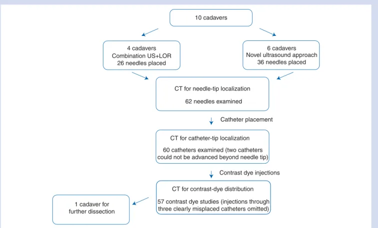
All the following examination sequences are depicted in Figure 1. Once the needles were in place, the first CT scan was performed. Imaging was executed on a six-row multi-slice CT (MSCT) scanner (Somaton Emotion 6, Siemens Medical Solutions, Siemens, Mu¨nchen, Germany). Raw data
10 cadavers
4 cadavers Combination US+LOR
26 needles placed
6 cadavers Novel ultrasound approach
36 needles placed
CT for needle-tip localization
CT for catheter-tip localization
CT for contrast-dye distribution
Contrast dye injections Catheter placement 62 needles examined
60 catheters examined (two catheters could not be advanced beyond needle tip)
1 cadaver for further dissection
57 contrast dye studies (injections through three clearly misplaced catheters omitted)
Fig 1 The flow chart shows the different examination sequences. Two ultrasound approaches have been tested and analysed the same way. After needle placements, the purpose of the first CT examination was to evaluate the exact location of the needle tip. Thereafter, catheters were threaded through the needles and again the exact location of the catheter tip was assessed by CT imaging. Finally, the contrast dye was injected through the catheters to study the contrast dye spread.
acquisition of the thoracic spine was performed with the fol-lowing settings: 110 kV; 100 mA; collimation, 6×1 mm. Image reconstruction was carried out in a slice thickness of 1.25 mm with an increment of half the slice thickness in soft tissue and bone-weighted reconstruction kernel. Primary image review and three-dimensional reconstructions were performed on a CT workstation (Leonardo, Siemens Medical Solutions, Siemens). For final evaluation, a special workstation (IDS5, Sectra AB, Linko¨ping, Sweden) was used.
After the initial CT scan, to confirm the position of the needles, the catheters were inserted through the needles and the needles were then removed. The depth of insertion varied from case to case by randomly introducing the catheter either 1, 2, or 3 cm beyond the tip of the needle. Randomization of depth was performed using a computer-generated list. After the placement of the catheters, a second CT scan of the thorax was performed to assess the location of the catheter tips. Subsequently, the contrast dye (10 ml Iopamidol, Iopamiro300wBraco Suisse SA,
Mendi-sio; diluted 1:5 with normal saline) was injected through half of the catheters at different levels to produce an initial spread of contrast dye. A third CT scan was performed for the first contrast dye spread analysis. Finally, non-diluted contrast dye was injected through the remaining catheters and recorded by a fourth CT scan for a second contrast dye spread analysis. By using two injections of different contrast dye dilutions, misinterpretation occurring due to the overlap of the spread of the contrast dye of two neighbouring cath-eters could be avoided.
Combination of an ultrasound-based method with
the classical loss-of-resistance technique
The first approach consisted of an ultrasound-guided initial placement of the needle tip on the transverse process with a subsequent redirection of the needle below the transverse process. Because, in the middle thoracic area, cranial of the transverse process, the rib is overlapping cranially and would be punctured, we were choosing the approach below the transverse process. Thereafter, the needle was further advanced through the superior costo-transverse ligament until a loss of resistance (LOR) to water was felt. For this purpose, a transverse sonogram of the vertebral column, with visualization of the transverse process, was obtained. Needle guidance was achieved by an out-of-plane technique with the aim to perform an orthogonal approach to the PVS, parallel to the vertebral column, in contrast to the slightly oblique approach in our first study.15 The orthogonal approach should lower the chance for an epidural catheter position. A combination of an ultrasound-based method with the classical LOR technique was chosen due to the dif-ficulties in visualizing the superior costo-transverse ligament in lots of cases unless an oblique sonographic scanning was performed.15 Furthermore, the anterior border of the ligament is hardly visible by ultrasound and the LOR should help to identify the needle tip passing the ligament and entering the PVS. After the first four cadavers
(26 procedures), we performed an interim analysis, since the LOR was hard to feel in most cases.
The pure ultrasound-guided approach
After the interim analysis, we developed a pure ultrasound-guided (PUSG) approach, which improved the ability to access and monitor the depth of the needle. Because the visi-bility of the superior costo-transverse ligament is difficult to achieve in many individuals as mentioned above, our aim was to design a simpler ultrasound-guided approach not reliant on the identification of this structure to reliably place a needle close to the intervertebral foramen. The procedure consisted of several steps: the needle was first positioned to contact the posterior –lateral border of the inferior articular process of a vertebra in an out-of-plane approach as shown in Figure 2. From this point, the needle was then directed slightly lateral, walked-off the bone, and advanced a few milli-metres deeper under the direct vision. The correct needle pos-ition was confirmed by injecting 1 –2 ml of normal saline and visualizing the anterior displacement of the pleura. The displa-cement of the pleura during injection is mandatory and con-firms the correct spread of the injected fluid in the PVS. If the spread of the injected fluid was dorsal to the bony land-mark (into the erector spinae musculature), the needle was further advanced 2 mm. A second injection of saline was per-formed to confirm a correct needle-tip position.
Cadaver dissection
One cadaver was dissected (thorax opened and lung removed, allowing direct sight to the pleura) to allow direct observation of the needle-tip position and the path taken by catheters during insertion through the needle. After ultrasound-guided placement of 10 needles 0.3 ml methyl-ene blue 1% was injected through each needle to mark the needle-tip position. Thereafter, catheters were placed and a further 1 ml methylene blue was injected through the cath-eters to assess the catheter-tip position. Thereafter, the cadaver was further dissected to explore the spread of methylene blue and the extent and location of the endothor-acic fascia and its connections.
Measurements
All CT scan analyses—with the exception of the interim ana-lyses after four cadavers—were performed after termination of data acquisition. All needle- and catheter-tip positions were assessed with regard to the following different anatom-ical positions according to Figure 3. Names in brackets rep-resent the wording used in the different figures and tables.
(1) Paravertebral, in proximity to the intervertebral foramen and the nerve root (near foramen). The aim of the study was to achieve contrast dye spread in this compartment (block of the nerve root).
(2) Paravertebral, lateral from the intervertebral foramen (intercostal).
(3) Paravertebral, at the level of the vertebral body in proximity to the sympathetic trunk (vertebral).
(4) Prevertebral or mediastinal (prevertebral).
(5) Dorsal, superficial to the PVS in the erector spinae musculature (muscle).
(6) Epidural (epidural).
(7) Pleural (pleural)—this anatomical space is clearly defined and therefore not shown schematically in Figure3. The contrast dye spread was analysed with regard to the same anatomic structures as with the needle and catheter tips. If more than 33% of the contrast dye was found in one of the above-mentioned anatomical locations, 1 count was added to the total number at the respective location. Additionally, the numbers of segments covered by the injected contrast were assessed.
The failure rate for needle- and catheter-tip locations was defined as needle tips/catheters lying dorsal to the PVS (namely in the erector spinae musculature) and intrapleural, epidural, or in the lungs.
Statistics
Metric data are presented as mean and standard deviation. Needle and catheter failure rate were calculated as percen-tage of all needles and catheters introduced, respectively.
Proportions of needle or catheter tips with regard to the defined anatomical sites were calculated.
Results
Needle placements
A total of 62 paravertebral punctures were performed in 10 cadavers. All needle tips were localized by MSCT scanning. The number of needle tips found in each compartment as defined in Figure3is shown in Table1. For the combination of an ultrasound-based method with the classical LOR tech-nique, 13 needle tips were found near the intervertebral foramen (paravertebral, near foramen), 11 needle tips were found anterior to the intervertebral foramen near the ver-tebral body (paraverver-tebral, verver-tebral), and two needles were not advanced enough and the tips were found in the erector spinal muscle (muscle). This resulted in an overall failure rate of 7.7% for this approach.
For the PUSG technique, all 36 needle tips were located in the PVS, and with the exception of two which lay lateral to the intervertebral foramen (paravertebral, intercostal), all needle tips were found at the level of the intervertebral foramen (paravertebral, near foramen). A typical example is shown in Figure 4. Overall success rate for the PUSG approach was therefore 100%.
A 1 1 1 A B Transverse process
Lamina arcus vertebrae and lateral border of inferior articular process
*
BFig 2 On the left side, the two different positions of the ultrasound probe described below during the procedure are shown as white rectangles in relation to the radiological reconstruction of the vertebral column in this cadaver. On the right side, the corresponding ultrasound images to the two transducer positions A and B in the same cadaver are shown. First, the probe is placed in order to visualize the transverse process (more cranial transducer positionA). Then, the probe is slightly moved caudally until no transverse process or rib is visible anymore and
the pleura can be visualized laterally (more caudal transducer positionB). Using this transducer position (B) the needle can first be placed
on the inferior articular process and then walked-off laterally over the edge of the bone or the needle tip can reliably be placed under ultra-sound sight directly into the PVS (asterisk). 1¼spinal process (left side) and dorsal shadowing of the spinal process in the ultraultra-sound images, respectively.
Catheter placements
We successfully placed a total of 60 paravertebral catheters and localized the catheter tips by CT scanning (Table 1). Two catheters could not be advanced beyond the needle tip despite turning the needle axis, resulting in an overall catheter placement failure rate of 3.3% (overall failure rate with both methods). When using the combination of an ultrasound-based method with the classical LOR technique: out of 26 catheters, one could not be advanced and five
were found outside the PVS (two prevertebral and three in the erector spinal muscle) resulting in a failure rate of 23.1%. With the PUSG technique: out of 36 catheters, one could not be advanced and 11 catheter tips were found outside the PVS (nine prevertebral, one muscle, and one pleural), despite all needle tips being placed in the PVS. Failure rate of catheter pla-cement with this approach was therefore 33.3%.
Although our PUSG approach revealed that 34 (out of 36) needle tips were correctly positioned near to the interverteb-ral foramen, only five (13.9%) of all catheter tips were finally found in this compartment, whereas 17 catheter tips were located anteriorly in the vicinity of the vertebral body and the sympathetic trunk (paravertebral, vertebral). A typical case is shown in Figure5. In summary, the majority of the cases demonstrated that catheters could not be located at the initial needle-tip position, irrespective of the insertion depth of the catheters (randomly 1, 2, or 3 cm).
Contrast dye study
These results are summarized in Table2and examples of the different patterns of contrast dye distribution are illustrated in Figures5and6. Of the 60 catheters placed, we examined dye distribution in 57. The contrast dye injection was omitted in three catheters due to their clear and total (not only cath-eter tip) misplacement outside the PVS (one cathcath-eter pleural and two catheters clearly in the erector spinal muscle).
The main direction of contrast dye distribution was anterior. Therefore, we found more than 33% of all injected contrast in the vicinity of the vertebral bodies (paravertebral, vertebral) in 33 cases and prevertebral in 26 cases. In six cases, there was epidural [over 7.7 (3.5) segments] and in four cases pleural [over 6.3 (1.5) segments] contrast spread, although no catheter was found epidural and only one pleural.
Dissection of the cadaver
The dissection revealed that the endothoracic fascia is very thin and not firmly attached to the vertebral bodies. Seven out of 10 catheter tips perforated the endothoracic fascia and were found in the prevertebral region.
4
3
6 1
2 5
Fig 3Axial CT image of one of the study subjects shows the different possible final positions of the needles, catheters, or the contrast dye which were evaluated by the forensic radiol-ogist. (1) Needle, catheter tip, or contrast paravertebral, in proxi-mity to the intervertebral foramen and the nerve root (near foramen). (2) Paravertebral, lateral from the intervertebral foramen (intercostal). (3) Paravertebral, at the level of the ver-tebral body in proximity to the sympathetic trunk (verver-tebral). (4) Prevertebral or mediastinal (prevertebral). (5) Dorsal (super-ficial) of the PVS in the erector spinae musculature (muscle). (6) Epidural (epidural). (7) Pleural (pleural)—this anatomical space is clearly defined and therefore not shown schematically in the figure.
Table 1Needle- vs catheter-tip localizations are shown. In two cadavers, one catheter could not be advanced beyond the needle tip. A few catheters were localized behind the PVS, despite the correct needle position in the PVS. This might have occurred during manipulation of the needle by advancing the catheter. Only one catheter was found to lie in the pleural cavity. LOR, loss-of-resistance method; PUSG, pure ultrasound guided. Data are numbers (%).
Needle-tip location (n562) Catheter-tip location (n562)
LOR (n526) PUSG (n536) LOR (n526) PUSG (n536)
1. Paravertebral, near foramen 13 (50) 34 (94) 3 (12) 5 (14)
2. Paravertebral, intercostal 0 2 (6) 2 (8) 2 (6) 3. Paravertebral, vertebral 11 (43) 0 15 (58) 17 (47) 4. Prevertebral 0 0 2 (8) 9 (25) 5. Muscle 2 (8) 0 3 (12) 1 (3) 6. Epidural 0 0 0 0 7. Pleural 0 0 0 1 (3)
The raw data from this study relating to needle and cath-eter placement and the distribution of dye are provided in Supplementary Tables S1 and S2.
Discussion
This study evaluated (i) an ultrasound-guided paravertebral approach combined with LOR technique and (ii) a PUSG
technique to the PVS. By combining ultrasound with the LOR technique, it was possible to simultaneously visualize the transverse process and the lung, but the puncture depth (defined as clear LOR) was difficult to discern in a lot of cases. A possible explanation is that the superior costo-transverse ligament may be missed due to the presence of gaps. Accordingly, as the penetration of the needle through Fig 4 In this reconstructed image, all needles introduced on the left side are visible (at TH 2, TH 8, and TH 11). The right picture shows a cross-section at the level of TH 11. The two needle tips are located near the dorsal part of the intervertebral foramen.
Fig 5 On the left image, the catheters are placed and the needles are retrieved. The catheter on the left-hand side has been introduced 2 cm, whereas the catheter on the right-hand side has been introduced 3 cm. The arrows indicate the catheter tips. On the right image, contrast dye distribution after injection through the left catheter is visible (the CT scan is not exactly the same position in relation to the vertebrae). The main portion of the contrast dye is in the vicinity of the vertebral body and in the prevertebral area (more anterior than the catheter tip). There is a small amount of the contrast dye in the intervertebral foramen and in the epidural space.
the superior costo-transverse ligament into the PVS could not clearly be detected, 7.7% of the needles were not advanced enough and located superficial to the PVS. On the other hand, 42.3% of the needles were advanced deeper than the intervertebral foramen to the vertebral level.
Therefore, we changed the technique and developed a novel approach which was not reliant on the visualization of the ligament. The novel approach uses the inferior lateral border of the articular process as a reference, an easily ultrasound visible bony landmark, rather than the poorly visible superior costo-transverse ligament.15 With this approach, no needle was placed too superficial or too deep and 94.4% of the needle tips were found in immediate proximity to the intervertebral foramen (the remaining two needles were found slightly lateral at an intercostal position). The main target of the paravertebral block is to reach the nerve root by the injected local anaesthetic; therefore, one aim of the study was to place the needle tip at this location. With the new ultrasound technique, the needle approach to the PVS is more medial compared with the LOR approach. This may have further distinct benefits: as the wedge-shaped PVS has a wider base medial (closer to the vertebral column) compared with the narrower apex more lateral, the likelihood of misplacing the needle into the pleural space may be reduced. Our findings indicate that ideal catheter placement is not dependent on correct needle-tip placement. The final position of the catheter was highly variable and once intro-duced through the needle often found its way into the anterior part of the PVS (anterior to the intervertebral foramen) in more than 50% of cases. In this position, reliable block of the intercostal nerves using the catheter is difficult. Even introducing the catheter only 1 cm beyond, the needle tip did not prevent the catheter from reaching the anterior part of the PVS.
By analysing the pattern of contrast dye spread, we observed a frequent distribution of dye away from the roots of the intercostal nerves. Important portions of injected con-trast were found in 59 cases anterior to the foramen at a ver-tebral or even preverver-tebral position, and in 18 cases, important contrast spread was found in the intercostal space. These are not new findings and have previously been reported in other studies.18–21 Some authors raised the question whether there could be a membrane in the PVS responsible for this unpredictable spread.18 21–23 The endothoracic fascia is such a membrane, formed by a thin layer of loose connective tissue. It lines the surface of the entire chest cavity including the diaphragm, fuses dorsally with the periosteum of the vertebral body,24and lies super-ficial to the pleura (between the pleura and the inner inter-costal muscles and the ribs, respectively). The presence of the endothoracic fascia could explain a contrast spread as described above. If contrast is injected anterior (ventral) to the endothoracic fascia, anterior and intercostal spread without reaching the intervertebral foramen can be explained. In our dissected cadaver, the endothoracic fascia was very thin and consisted of areolar-like connective tissue not strong enough to prevent the catheter perforating it on insertion. Catheters perforating the endothoracic fascia might explain the high incidence of catheter misplacement anterior to the intervertebral foramen, despite having the needle tip placed at the level of the intervertebral foramen. This could also explain why small amounts of the contrast Table 2Contrast dye distribution after injection of 10 ml of
contrast through the catheters (n¼57). If more than 33% of the total amount of the contrast dye was found in the subsequent compartment by CT scan, this compartment was counted in the contrast distribution in this table. The mean segmental spread of the contrast dye distribution was calculated in these cases. Data are numbers and mean (SD).
Contrast spread >33% of contrast found Spread number of segments 1. Paravertebral, near foramen 6 1.3 (0.8) 2. Paravertebral, intercostal 18 2.5 (1.4) 3. Paravertebral, vertebral 33 4.2 (1.4) 4. Prevertebral 26 4.0 (1.1) 5. Muscle 5 3.0 (2.3) 6. Epidural 6 7.7 (3.5) 7. Pleural 4 6.3 (1.5) F L R CRAN/CAUD -10
Fig 6 The reconstructed image shows contrast dye distribution after injection through the catheter at the level TH 11 on the left and through the catheter at the level TH 8 on the right side. There are two different patterns of distribution. On the left side, the main part of the contrast dye is visible close to the ver-tebral body with a cranio-caudal distribution over three segments and with a small amount in one intercostal space. On the right side, there is mainly an intercostal spread covering two segmen-tal levels.
dye could be found in the epidural space, despite a major volume of the contrast dye being located at the level of the vertebral bodies. Either the endothoracic fascia does not prevent the contrast dye from flowing through (endothoracic fascia with holes, not impermeable to fluid) or the contrast dye runs back along to the catheter. Another explanation could be the catheters used. The orifices for injection are not located at the catheter tip but distributed along the first 1.5 cm of the catheter end. Thus, the distal orifices could have been located ventral from the endothoracic fascia, whereas the proximal orifices are located dorsal from the fascia.
The additional use of CT scanning and reconstruction of the images allows for the detection of epidural spread,15 25which is often missed (or not apparent) when using conventional chest X-ray or fluoroscopic imaging only.18–21 26–30 The common finding of epidural spread in the two studies using CT scanning can be explained by the medial direction of the puncture, close to the vertebral column,15and the close proxi-mity of the intervertebral foramen to the final needle pos-ition,25 as indicated in our study. We found a frequent epidural contrast dye spread. In six cases, there was a mean spread over 7.7 vertebral segments. This occurred despite the chosen orthogonal or slight medial to lateral orientation of the needle. The finding allows us to raise the same specu-lative question as Karmakar and colleagues31and Cowie and colleagues,32that is, ‘Is a multisegmental sensory anaesthe-sia after paravertebral block, the result of epidural spread?’.
There are some limitations to this study. The tissue proper-ties of living human subjects are different from cadavers and this may slightly limit the validity of our findings with respect to clinical practice. However, it has recently been shown that among methods of preservation of cadavers, Thiel’s embalm-ing seems to most resemble livembalm-ing tissue.33We punctured the PVS under the transverse process because above, especially in the middle thoracic area, the rib is overlapping and would be encountered. We angulated the needles from caudal to cranial (as can be seen in Fig.4), but we cannot exclude that this relative straight course to the PVS may facilitate the anterior catheter positions.
In conclusion, with the described rather simple ultrasound approach to the PVS, the needle can be accurately placed close to the intervertebral foramen and thus close to the emerging intercostal nerves. As in other studies, catheter placement appears unreliable and the injected contrast dye over the catheters showed multiple patterns of spread. An important issue in the future will be the development of new paravertebral catheters. The development of a soft pigtail catheter with a tip remaining close to the needle tip could be promising in the future.
Supplementary material
Supplementary material is available at British Journal of Anaesthesia online.
Acknowledgements
We thank the Department of Anatomy of the University of Bern for providing the cadavers and the location for the study. Special thanks to Susanne Boemke, Kati Ha¨nssgen, and Hans Grossmann, Department of Anatomy, for their help throughout the study. We thank the Centre for Forensic Imaging and Virtopsy, Institute of Forensic Medicine, Univer-sity of Bern, for using the CT scanner and for the image analysis and reconstructions. Special thanks to Barry Nicholls, Musgrove Park Hospital, Taunton, UK, for proofreading the manuscript and for his suggestions.
Funding
This study was supported by a research grant from the Euro-pean Society of Regional Anaesthesia (ESRA) and an insti-tutional research grant from the University Department of Anaesthesiology and Pain Therapy, University Hospital and University of Bern, Bern, Switzerland.
Conflict of interest
None declared.
References
1 Vogt A, Stieger DS, Theurillat C, Curatolo M. Single-injection thoracic paravertebral block for postoperative pain treatment after thoracoscopic surgery. Br J Anaesth 2005; 95: 816 –21 2 Richardson J, Sabanathan S, Jones J, et al. A prospective,
randomized comparison of preoperative and continuous balanced epidural or paravertebral bupivacaine on post-thoracotomy pain, pulmonary function and stress responses. Br J Anaesth 1999; 83: 387 –92
3 Perttunen K, Nilsson E, Heinonen J, et al. Extradural, paravertebral and intercostal nerve blocks for post-thoracotomy pain. Br J Anaesth 1995; 75: 541 –7
4 Matthews PJ, Govenden V. Comparison of continuous paraverte-bral and extradural infusions of bupivacaine for pain relief after thoracotomy. Br J Anaesth 1989; 62: 204 –5
5 Ganapathy S, Murkin JM, Boyd DW, Dobkowski W, Morgan J. Con-tinuous percutaneous paravertebral block for minimally invasive cardiac surgery. J Cardiothorac Vasc Anesth 1999; 13: 594 –6 6 Weltz CR, Greengrass RA, Lyerly HK. Ambulatory surgical
manage-ment of breast carcinoma using paravertebral block. Ann Surg 1995; 222: 19– 26
7 Klein SM, Bergh A, Steele SM, Georgiade GS, Greengrass RA. Thoracic paravertebral block for breast surgery. Anesth Analg 2000; 90: 1402– 5
8 Pusch F, Freitag H, Weinstabl C, et al. Single-injection paraverte-bral block compared to general anaesthesia in breast surgery. Acta Anaesthesiol Scand 1999; 43: 770– 4
9 Richardson J, Vowden P, Sabanathan S. Bilateral paravertebral analgesia for major abdominal vascular surgery: a preliminary report. Anaesthesia 1995; 50: 995 –8
10 Kirvela O, Antila H. Thoracic paravertebral block in chronic post-operative pain. Reg Anesth 1992; 17: 348– 50
11 Eason MJ, Wyatt R. Paravertebral thoracic block—a reappraisal. Anaesthesia 1979; 34: 638– 42
12 Moorthy SS, Dierdorf SF, Yaw PB. Influence of volume on the spread of local anesthetic-methylene blue solution after injection for intercostal block. Anesth Analg 1992; 75: 389–91
13 Mowbray A, Wong KK. Low volume intercostal injection. A com-parative study in patients and cadavers. Anaesthesia 1988; 43: 633– 4
14 Mowbray A, Wong KK, Murray JM. Intercostal catheterisation. An alternative approach to the paravertebral space. Anaesthesia 1987; 42: 958– 61
15 Luyet C, Eichenberger U, Greif R, et al. Ultrasound-guided paraver-tebral puncture and placement of catheters in human cadavers: an imaging study. Br J Anaesth 2009; 102: 534– 9
16 Thiel W. The preservation of the whole corpse with natural color. Ann Anat 1992; 174: 185 –95
17 Dittmann V, Fasel JH, Hornung J, et al. Use of corpses and body parts in medical research and education, continuing education and training. Schweizerische A¨rztezeitung 2009; 04: 102– 7
18 Cheema S, Richardson J, McGurgan P. Factors affecting the spread of bupivacaine in the adult thoracic paravertebral space. Anaesthesia 2003; 58: 684– 7
19 Lo¨nnqvist PA, Hesser U. Radiological and clinical distribution of thoracic paravertebral blockade in infants and children. Paediatr Anaesth 1993; 3: 83– 7
20 Carabine UA, Gilliland H, Johnston JR, McGuigan J. Pain relief for thoracotomy. Comparison of morphine requirements using an extrapleural infusion of bupivacaine. Reg Anesth 1995; 20: 412– 7
21 Naja MZ, Ziade MF, El Rajab M, El Tayara K, Lonnqvist PA. Varying anatomical injection points within the thoracic paravertebral space: effect on spread of solution and nerve blockade. Anaes-thesia 2004; 59: 459 –63
22 Cheema SP, Ilsley D, Richardson J, Sabanathan S. A thermographic study of paravertebral analgesia. Anaesthesia 1995; 50: 118 –21
23 Karmakar MK, Chung DC. Variability of a thoracic paravertebral block. Are we ignoring the endothoracic fascia? Reg Anesth Pain Med 2000; 25: 325–7
24 Dugan DJ, Samson PC. Surgical significance of the endothoracic fascia. The anatomic basis for empyemectomy and other extra-pleural technics. Am J Surg 1975; 130: 151– 8
25 Purcell-Jones G, Pither CE, Justins DM. Paravertebral somatic nerve block: a clinical, radiographic, and computed tomographic study in chronic pain patients. Anesth Analg 1989; 68: 32 –9 26 Lonnqvist PA. Continuous paravertebral block in children. Initial
experience. Anaesthesia 1992; 47: 607– 9
27 Karmakar MK, Kwok WH, Kew J. Thoracic paravertebral block: radiological evidence of contralateral spread anterior to the vertebral bodies. Br J Anaesth 2000; 84: 263– 5
28 Soni AK, Conacher ID, Waller DA, Hilton CJ. Video-assisted thora-coscopic placement of paravertebral catheters: a technique for postoperative analgesia for bilateral thoracoscopic surgery. Br J Anaesth 1994; 72: 462 –4
29 Naja ZM, El-Rajab M, Al-Tannir MA, et al. Thoracic paravertebral block: influence of the number of injections. Reg Anesth Pain Med 2006; 31: 196–201
30 Richardson J, Jones J, Atkinson R. The effect of thoracic paraver-tebral blockade on intercostal somatosensory evoked potentials. Anesth Analg 1998; 87: 373 –6
31 Karmakar MK, Booker PD, Franks R, Pozzi M. Continuous extrapleural paravertebral infusion of bupivacaine for post-thoracotomy analgesia in young infants. Br J Anaesth 1996; 76: 811–5 32 Cowie B, McGlade D, Ivanusic J, Barrington MJ. Ultrasound-guided
thoracic paravertebral blockade: a cadaveric study. Anesth Analg 2000; 110: 1735– 9
33 Benkhadra M, Faust A, Ladoire S, et al. Comparison of fresh and Thiel’s embalmed cadavers according to the suitability for ultrasound-guided regional anesthesia of the cervical region. Surg Radiol Anat 2009; 31: 531 –5