HAL Id: hal-01794116
https://hal.archives-ouvertes.fr/hal-01794116
Submitted on 17 May 2018
HAL is a multi-disciplinary open access
archive for the deposit and dissemination of
sci-entific research documents, whether they are
pub-lished or not. The documents may come from
teaching and research institutions in France or
abroad, or from public or private research centers.
L’archive ouverte pluridisciplinaire HAL, est
destinée au dépôt et à la diffusion de documents
scientifiques de niveau recherche, publiés ou non,
émanant des établissements d’enseignement et de
recherche français ou étrangers, des laboratoires
publics ou privés.
Ductility prediction of substrate-supported metal layers
based on rate-independent crystal plasticity theory
Mohamed Ben Bettaieb, Farid Abed-Meraim
To cite this version:
Mohamed Ben Bettaieb, Farid Abed-Meraim. Ductility prediction of substrate-supported metal
lay-ers based on rate-independent crystal plasticity theory. International Journal of Material Forming,
Springer Verlag, 2019, 12 (2), pp.241-255. �10.1007/s12289-018-1401-z�. �hal-01794116�
Science Arts & Métiers (SAM)
is an open access repository that collects the work of Arts et Métiers ParisTech
researchers and makes it freely available over the web where possible.
This is an author-deposited version published in: http://sam.ensam.eu
Handle ID: .http://hdl.handle.net/null
To cite this version :
Mohamed BEN BETTAIEB, Farid ABED-MERAIM - Ductility prediction of substrate-supported metal layers based on rate-independent crystal plasticity theory - International Journal of Material Forming p.1-15 - 2018
Any correspondence concerning this service should be sent to the repository Administrator : archiveouverte@ensam.eu
Ductility prediction of substrate-supported metal layers based
on rate-independent crystal plasticity theory
Mohamed Ben Bettaieb 1,2 & Farid Abed-Meraim 1,2
Abstract
In several modern technological applications, the formability of functional metal components is often limited by the occurrence of localized necking. To retard the onset of such undesirable plastic instabilities and, hence, to improve formability, elastomer substrates are sometimes adhered to these metal components. The current paper aims to numerically investigate the impact of such elastomer substrates on the formability enhancement of the resulting bilayer. To this end, both the bifurcation theory and the initial imperfection approach are used to predict the inception of localized necking in substrate-supported metal layers. The full- constraint Taylor scale-transition scheme is used to derive the mechanical behavior of a representative volume element of the metal layer from the behavior of its microscopic constituents (the single crystals). The mechanical behavior of the elastomer substrate follows the neo-Hookean hyperelastic model. The adherence between the two layers is assumed to be perfect. Through numerical simulations, it is shown that bonding an elastomer layer to a metal layer allows significant enhancement in formability, especially in the negative range of strain paths. These results highlight the benefits of adding elastomer substrates to thin metal components in several technological applications. Also, it is shown that the limit strains predicted by the initial imperfection approach tend towards the bifurcation predictions as the size of the geometric imperfection in the metal layer reduces.
Keywords Substrate-supported metal layers . Forming limit diagrams . Localized necking . Neo-Hookean model . Rate-independent crystal plasticity . Bifurcation and imperfection analyses
Introduction
Ductile failure is the main mechanism that limits the formabil- ity of thin metal sheets during forming processes; therefore, this phenomenon is central in structural integrity assessment together with corrosion and fatigue. Several possible failure scenarios, or mechanisms, may occur during forming opera- tions. In this field, one can quote at least three main scenarios. The first one takes place only for very pure metals. In this case, thin metal sheets fail without the occurrence of damage, owing to the absence of void nucleation sites. In such circum- stances, the deformation state is homogeneous at the
* Mohamed Ben Bettaieb Mohamed.BenBettaieb@ensam.eu
1
LEM3, UMR CNRS 7239, Arts et Métiers ParisTech, 4 rue Augustin Fresnel, 57078 Metz Cedex 3, France
2
DAMAS, Laboratory of Excellence on Design of Alloy Metals for low-mAss Structures, Université de Lorraine, Lorraine, France
beginning of the loading and, at a certain limit strain, the deformation starts concentrating in narrow bands. The emer- gence of such bands marks the development of localized neck- ing in the sheet. The second scenario corresponds to the local- ization of plastic strain into shear bands owing to various possible softening mechanisms. Subsequently, following the accumulation of large plastic strains and the increase of stress triaxiality in the necked regions, voids nucleate, grow and coalesce to produce final material separation. The third mech- anism involves damage nucleation in the material prior to plastic strain localization. The softening induced by the accu- mulated porosity is sufficient to counteract the strain harden- ing capacity of the material and leads to plastic strain locali- zation in narrow bands. An extensive study of the different failure mechanisms and the competition between them has been reported in [1]. In the current contribution, we assume that the failure of the studied sheet metals is only due to local- ized necking, without prior occurrence of damage. For inter- ested readers, an exhaustive academic presentation of the pre- diction of failure in metallic materials, based on advanced damage models, can be found in [2]. It is now
well-recognized that the accurate prediction of the limit strains that lead to localized necking is crucial for designing functional or structural components used in industrial devices. To this end, several numerical models have been developed for the predic- tion of localized necking, and the associated limit strains are represented in terms of the so-called forming limit diagram (FLD). This FLD concept was originally introduced by Keeler and Backofen [3], for representing the limit strains in the range of positive strain paths, and has been extended by Goodwin [4] to the range of negative strain paths. Over the last decades, two major challenges, related to the formability of metallic components, have been extensively studied both from academic and industrial points of view. The first issue is of scientific nature and is associated with the accurate predic- tion of the formability limit of the studied material, while the second, of practical nature, is related to the development of industrial solutions to improve its formability.
To solve the first issue, related to the accurate determina- tion of formability limits, several experimental methods have been developed and widely used in both academic and indus- trial environments. Unfortunately, the use of these experimen- tal techniques has been limited by various practical difficul- ties, such as the high cost of the experimental tests required for characterizing an FLD. To avoid these difficulties, several analytical and numerical approaches have been set up in the literature as alternatives to the experimental characterization of FLDs (see, e.g., [5, 6]). These alternative approaches re- quire the use of a criterion, to predict the occurrence of strain localization, along with a constitutive model to describe the evolution of the mechanical state of the studied material. Despite their good predictive capabilities, the phenomenolog- ical constitutive models, which are the most widely used for the numerical prediction of FLDs, are not able to properly account for some essential physical and mechanical features, such as initial and induced textures and other microstructure- related parameters (crystallographic structure, dislocation mo- tion, initial morphology of grains, slip on crystallographic planes ...). These limitations represent the main motivation behind the more recent use of micromechanical modeling for FLD prediction. The advantage of such physically-based modeling, compared to phenomenological approaches, is its ability to link, in a natural and explicit way, the material mi- crostructure to the formability of the studied sheets. Due to this major advantage, a micromechanical approach is adopted in the current paper to model the mechanical behavior of a small volume element, which is assumed to be representative of the studied metal sheet. The constitutive law of this repre- sentative volume element (RVE) is determined from that of its microscopic constituents (the single crystals) by using the full- constraint Taylor scale-transition scheme. The mechanical be- havior at the single crystal scale is described by a finite strain rate-independent constitutive model, in which the Schmid law is used to govern the plastic flow. This rate-independent
formulation is more suitable for the modeling and the simula- tion of cold forming processes, where viscous effects are lim- ited. The developed model is applied in the current study to single crystals with FCC crystallographic structure. In order to predict the onset of localized necking, the polycrystalline con- stitutive model, based on the full-constraint Taylor scheme, is coupled with two different localization criteria: the bifurcation theory, originally developed by Rice [7], and the imperfection approach initiated by Marciniak and Kuczynski [8]. Note that coupling these localization criteria (especially the Marciniak and Kuczynski approach) with the Taylor multiscale scheme is a very challenging problem, from a numerical point of view. Hence, the algorithmic aspects related to this coupling are detailed in the current paper. The use of the Taylor model, instead of other more elaborate (and more complex) multiscale schemes, such as the CPFEM model or the self- consistent approach, allows a considerable reduction in the CPU time required to determine a complete FLD (especially within the initial imperfection approach). However, it is well known that the Taylor multiscale scheme predicts high stress values compared to the self-consistent scheme.
To solve the above-mentioned second issue, related to the improvement of formability of industrial components, a num- ber of technological solutions have been proposed and used in various industrial applications. One of the most-widely used solutions consists in perfectly bonding an elastomer substrate to the original metal component. This technological solution has proven its effectiveness in the improvement of formability of industrial devices [9–13]. For instance, in the design of electronic devices that require high stretchability levels, substrate-supported metal layers are being increasingly used. This is the case of stretchable conductors used in biomedical applications, as well as interconnects that are used in large- scale integrated circuits [9, 10]. The bifurcation theory and the initial imperfection approach, previously developed for the case of freestanding metal layers, are extended here to predict the formability of substrate-supported metal layers. The aim of this extension is to numerically investigate the impact of the addition of an elastomer substrate on the formability of the resulting metal/elastomer bilayer. Note that the formability of substrate-supported metal layers has been studied in very few numerical investigations in the past (see, e.g., [13, 14]). In addition, in these earlier contributions, only phenomeno- logical constitutive models have been used to describe the mechanical behavior of the metal layer. To the authors’ best knowledge, this is the first time a multiscale scheme is used to model the mechanical behavior of a metal layer, which is supported by an elastomer substrate, in order to analyze the formability of the resulting metal/substrate bilayer. In the cur- rent analysis, the mechanical behavior of the elastomer layer is assumed to obey the hyperelastic neo-Hookean constitutive law. Also, the adherence between the two layers is assumed to be perfect. Consequently, the effect of interfacial
¼
¼ delamination between the two layers on the ductility of the bilayer cannot be analyzed within the current framework and will be the subject of a future investigation.
The remainder of the paper is organized as follows: – The constitutive equations describing the mechanical
be-havior of the metal and elastomer layers will be outlined in the second Section.
– In the third Section, the theoretical framework for the two localization criteria will be presented.
– Various numerical results obtained by the application of the developed tool will be presented and discussed in the fourth Section.
Notations and nomenclature
The following notations and abbreviations are adopted in this paper:
– Mechanical fields corresponding to the polycrystal (resp. single crystal) scale are denoted by capital (resp. small) letters. To be consistent with the notations adopted for the metal layer, the different mechanical fields corresponding to the elastomer layer are also denoted by capital letters. – •PS: the in-plane part of a given field • (in relation with the
plane-stress assumption).
– •♦: quantity • associated with layer ♦ (metal or elastomer layer).
– •(B): quantity • associated with the band (M–K analysis). – •(S): quantity • associated with the safe zone (M–K
analysis).
– •0: the initial value of quantity •.
The constitutive modeling of the polycrystalline aggregate is achieved within the framework of finite strains. In the context of large deformations, several possible tangent moduli can be derived. These different choices are mainly dependent on the adopted stress and strain measures. In our case, we used the nominal stress rate N˙ as appropriate stress measure to express the constitutive equations and the bifurcation relations. The nominal stress tensor N is defined as the transpose of the first Piola–Kirchhoff stress tensor. The strain measure, which is work-conjugate to the nominal stress rate N˙ , corresponds to the velocity gradient G. This choice is motivated by the formu- lation of the bifurcation equations proposed by Rudnicki and Rice [15], who demonstrated that the most appropriate formu- lation for the bifurcation theory at finite strains requires the choice of these work-conjugate variables. Indeed, the use of these work-conjugate variables allows the automatic satisfac- tion of the rate (incremental) form of both the equilibrium and the compatibility conditions. Further details on this choice are provided in [15] and [16]. The macroscopic tangent modulus L linking N˙ to G is then obtained by using the Taylor model
N˙ ¼ L : G ð1Þ
According to the Taylor scale-transition scheme, the mac- roscopic velocity gradient G is assumed to be homogeneous over the polycrystalline aggregate:
∀I ¼ 1; …; N g : G ¼ gI ð2Þ
where Ng is the number of single crystals that compose the poly-
crystalline aggregate and gI is the velocity gradient of grain I. The macroscopic nominal stress rate N˙ is related to its microscopic counterpart n˙ by the following average relation:
1 – FM (resp. BL), in figures of BPrediction results^ Section,
refers to freestanding metal layer (resp. metal/elastomer N˙
V ∫V n˙ ðxÞ dx ð3Þ
bilayer).
These notations may be combined. For instance, tensor X in the elastomer layer of the band is denoted XE(B).
Mechanical behavior of the bilayer
Metal layer
Constitutive equations at the polycrystalline scale
Let us consider a polycrystalline aggregate, which is assumed to be statistically representative of the metal layer. The consti- tutive modeling of this aggregate is thus sufficient to accurately describe the mechanical behavior of the whole metal layer. To derive the constitutive law of the polycrystalline aggregate from that of its microscopic constituents, the Taylor model is used.
where x designates a material point within the polycrystalline aggregate.
In the same way, the macroscopic tangent modulus L is related to its microscopic counterpart l by a similar relationship:
1
L ∫V lðxÞ dx ð4Þ
V
Therefore, to compute the macroscopic tangent modulus L via Eq. (4), the microscopic tangent modulus l of all individual grains should be first computed. To this end, the following Section is dedicated to the derivation of the analytical expres- sion of the microscopic tangent modulus.
Constitutive equations at the single crystal scale
The mechanical behavior of the single crystals that make up the polycrystalline aggregate is described within a
rate-c ik ˙ β c β β β ( τ β τ β γ˙ β 0
independent constitutive framework. Because the single crys- ∀β ¼ 1; …; N s : < c ⇒ ¼β ð11Þ
tals undergo finite strains, the effect of lattice rotation is accounted for.
τ β ¼ τ β ⇒γ˙ ≥ 0 c
At the microscopic level, a behavior law similar to Eq. (1) can be obtained by combining the constitutive relations of the single crystal:
n
˙ ¼ l : g ð5Þ
The microscopic velocity gradient is additively split into its symmetric and skew-symmetric parts, denoted as d and w, respectively
d ¼ ð 1=2Þ (g þ gT); w ¼ ð 1=2Þ (g−gT) ð6Þ
The strain rate tensor d and the spin tensor w are split into their elastic and plastic parts
where τ β is the critical shear stress of the slip system β. The Cauchy stress tensor σ is related to the nominal stress tensor n by the following relation:
n ¼ j f −1:σ ð12Þ
where j is the Jacobian of the microscopic deformation gradi- ent f.
The index form of Eq. (12) is given as follows:
nij ¼ j f −1 σkj ð13Þ
The nominal stress rate n˙ involved in Eqs. (3) and (5) can be easily obtained from Eq. (12)
d ¼ de þ dp; w ¼ we þ wp ð7Þ n˙ ¼ j f−1:
(
σ˙ þ σ Tr ðdÞ−g:σ) ð14Þ
The rotation r of the single crystal lattice frame is related to the elastic part of the spin tensor we by the following relation:
In the current paper, an updated Lagrangian approach is adopted. Thus, in Eq. (14), f is set to the second-order identity tensor I2 and j is set to 1, which reduces to
˙
r:rT ¼ we ð8Þ
In order to satisfy the objectivity principle, the co-rotational rate σ∇ of the Cauchy stress tensor σ, with respect to the
n˙ ¼ σ þ σ Tr ðdÞ−g:σ ð15Þ
By combining Eqs. (6), (7), (9), (10) and (15), n˙ can be
β
lattice rotation, is related to the elastic strain rate de by the following hypoelastic law:
expressed as a function of the slip rates γ˙ n ˙ ¼ ðCe þ σ⊗I 2Þ : d−σ:w−d:σ β ð16Þ σ∇ ¼ σ˙ −we:σ þ σ:we ¼ Ce : de ð9Þ −∑ N s β¼1sgn ( τ β )(Ce : Rβ þ Sβ :σ−σ:Sβ ) γ˙
where Ce is the fourth-order elasticity tensor. The elastic be- havior of the metal layer is assumed to be isotropic and there- fore Ce is defined by the Young modulus E and the Poisson ratio ν.
The inelastic deformation is only due to the slip on the
Let us now introduce the set of active slip systems A; defined as the slip systems for which the slip rates are strictly positive. The set of slip systems β used in Eq. (16) is then reduced to the set A
n
˙ ¼ ðCe þ σ⊗I
2Þ : d−σ:w−d:σ
crystallographic planes. Thus, dp and wp can be defined by ( β )( e β β β ) ˙ β ð17Þ
the following relations: −∑β∈Asgn τ C : R þ S :σ−σ:S γ
dp ¼ ∑N s γ˙ βsgn ( τ β ) Rβ ; wp ¼ ∑N s γ ˙ βsgn (
τ β ) Sβ ð10Þ In order to obtain the expression of the microscopic tangent
β
β¼1 β¼1 modulus l from relation (17), the slip rates γ˙ of the active slip
where: systems should be expressed as functions of g. To this end, the consistency condition, restricted to the active slip systems, is used • Ns is the total number of slip systems (equal to 12 for FCC
crystallographic structure).
∀β∈A : χ˙
¼ sgn(τ β ) τ˙ −τ˙ c ¼ 0; γ˙ > 0 ð18Þ
• γ˙ β is the slip rate of the slip system β. By using the definition of the resolved shear stress as wellβ
• Rβ (resp. Sβ) is the symmetric part (resp. skew-symmetric part) of the Schmid orientation tensor.
• τβ is the resolved shear stress of the slip system β, which is
as Eqs. (7)1 and (9), the resolved shear stress rate τ˙
expressed as
can be
equal to σ : Rβ. ∀β∈A: τ˙ β¼ Rβ : σ∇ ¼ Rβ : Ce : (d−dpÞ ð19Þ
The Schmid law is used to model the plastic flow of the As to the time derivative of τ β , it is given by the following
β T A α τ n 1 ∀β∈A : τ˙
c ¼ h ∑α∈ γ˙ known indetermination problem), the pseudo-inversion
tech-h0 Γ
\n−1 h ¼ h0 1 þ
0 ; Γ ∑
N s γα ð20Þ
¼ α¼1 nique is used to invert it and then to compute the slip rates of
the active slip systems. For the other slip systems, belonging to the set of potentially active slip systems, their slip rates are where h0 is the initial hardening rate and n the power-law
hardening exponent. τ0 is the initial critical shear stress, which
is assumed to be the same for the different slip systems. It must be noted that the developed model and the corresponding numerical tools are not restricted to this particular hardening law, and can easily incorporate other hardening models.
The expression of the slip rates for the active slip systems is finally obtained by inserting Eqs. (10)1, (19) and (20) into the
consistency condition (18)
β
assumed to be equal to zero. After this step, the Schmid law given by Eq. (11) is checked for all of the potentially active slip systems. If at least one constraint of this Schmid law is violated, then the assumed set is not an effective set of active slip systems and another set is selected. Once the different mechanical variables are updated, the microscopic tangent modulus l is computed by using Eq. (23).
Elastomer layer
∀β∈A : γ˙ ¼ ∑α∈AM βαsgnðτ αÞ Rα : Ce : d
¼ yβ : d ð21Þ In contrast to the metal layer, the mechanical behavior of the elastomer layer is assumed to be homogeneous and is modeled where M is the inverse of matrix P of rank CardðAÞ, which is
defined by the following index form:
∀α; β∈A : Pαβ ¼ (h þ sgnðτ αÞ sgn(τ β ) Rα : Ce : Rβ ) ð22Þ
Combining Eqs. (5), (17) and (21), one can obtain the an- alytical expression of the microscopic tangent modulus l
l ¼ Ce þ σ⊗I2−1ΛðσÞ−2ΛðσÞ
by a hyperelastic neo-Hookean law [20]. The formulation of this model allows linking the Cauchy stress tensor Σ to the left
Cauchy–Green tensor V
Σ ¼ q I2 þ μ V2 ð25Þ
where μ is the shear modulus, q an unknown hydrostatic pres- sure to be determined by applying the incompressibility con-straint, and V is defined by the following relation:
α e α α α α ð23Þ
−∑α∈Asgnðτ Þ ðC : R þ S :σ−σ:S Þ⊗y V2 ¼ F: F ð26Þ
where 1Λ and 2Λ are fourth-order tensors that reflect the con- tribution of Cauchy stress convective terms
1
with F being the deformation gradient tensor of the elastomer layer.
In the particular case of plane-stress state (which will be
1Λ ijkl ðσÞ ¼ 2Λ ijkl ðσÞ ¼ ( δljσik −δkjσil ) 2 2 ( δik σlj þ δil σkj ) ð24Þ
adopted in BStrain localization criteria^ Section to apply the different localization criteria), the unknown hydrostatic pres- sure q is easily determined by using the plane-stress condition To incrementally integrate the constitutive equations, at the
single crystal scale, over a typical time increment [tn, tn + 1], an
implicit algorithm is used. This algorithm belongs to the fam- ily of ultimate algorithms (initially developed by Borja and Wren [17]), and is very similar to the one developed in [18]. By analyzing the above constitutive equations, one can easily notice that the determination of the set of active slip systems A; from the set of potentially active slip systems P (
¼ fβ ¼ 1; …; N s : τ β ðtnÞ ¼ τ β ðtnÞg ), as well as the
cor-(Σ33 = 0):
q ¼ −μ V 33 ð27Þ
Strain localization criteria
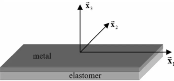
Let us consider a bilayer comprised of a metal layer M and an elastomer layer E (Fig. 1). We define an orthogonal Cartesian
c
responding slip rates γ˙ β allows the computation of all other mechanical variables. To this end, a combinatorial search strategy, very similar to the one proposed in [19], is used to determine the set of active slip systems from the set of poten- tially active slip systems. This search strategy is carried out iteratively and, at each iteration, a subset of the set of poten- tially active slip systems is selected to be the set of active slip systems. The slip rates corresponding to the presumed set of active slip systems are computed by using Eq. (21). If matrix P (see Eq. (22)) is singular (which corresponds to the
well-coordinate system (!x 1; !x 2; !x 3 ), which is tied to the bilayer.
The axes !x 1; !x 2 and !x 3 coincide with the rolling,
trans-verse, and normal directions of the sheet, respectively. The two layers are assumed to be perfectly adhered and sufficient- ly thin. Consistent with several literature works and consider- ing the thickness of the bilayer, the assumption of generalized plane stress is adopted in both localization criteria (namely the bifurcation theory and the initial imperfection approach). Hutchinson and Neale [21] have proven the validity of such an assumption in the case of thin structures (which is the case
the following generic forms: 0
1 0 0 1 0 ? ? 0 1
LPS ¼ ℒ þ Σ⊗Ι2−1ΛðΣÞ−2ΛðΣÞ ð34Þ
E
The generic forms of tensors 1Λ and 2Λ involved in rela-GM ¼ @ 0 ρ 0 A ; N˙ M ¼ @ ?
0 0 ? 0
? 0 A 0 0
tion (34) are given in Eq. (24).
The non-zero components of the fourth-order tensor ℒ are 0
1 0 0 1 0
? ? 0 1 ð30Þ defined by the following relations (see [14]):
GE ¼ @ 0 ρ 0 A ; 0 0 −ð1 þ ρÞ NE ¼ @ ? 0 ? 0 0 A0 8 ℒ 1111 ¼ 2 μ h e2 E11 þ e−2 ðE11þE22Þ i > L ¼ LPS M αβγδ E h i
The bifurcation criterion states that strain localization oc- curs when the acoustic tensor associated with the bilayer be- comes singular (see, e.g., [7]). Hence, this criterion is expressed in the following form:
→ → \
Fig. 1 Geometry of the bilayer and Cartesian coordinates
det N PS:LPS: N PS
where:
¼ 0 ð31Þ
in the current study). The plane-stress conditions are
→
• N PS is the unit vector (lying in the plane of the bilayer)
→ PS
expressed here in terms of out-of-plane components of the macroscopic nominal stress rate tensor N˙ in both layers by:
normal to the localization band. Here, N to (cos θ, sin θ).
is taken equal
N˙ 13 ¼ N˙ 31 ¼ N˙ 23 ¼ N˙ 32 ¼ N˙ 33 ¼ 0 ð28Þ
• LPS is the averaged plane-stress tangent modulus of the bilayer. This modulus is defined by the following relation:
h LPS h LPS
The numerical tools developed in the current paper are restricted to polycrystalline aggregates (which are assumed to be representative of the metal layer) with orthotropic initial
PS M M þ E E
hM þ hE
ð32Þ
texture. For this type of materials, the plane-stress assumption implies that the out-of-plane components of the macroscopic velocity gradient, in both layers, are equal to zero:
G13 ¼ G31 ¼ G23 ¼ G32 ¼ 0 ð29Þ
Bifurcation theory
where hM (resp. hE) is the current thickness of the metal (resp.
elastomer) layer and LPS (resp. LPS ) is the plane-stress tan-M E
gent modulus of the metal (resp. elastomer) layer.
M is derived from the 3D expression of the metal layer
tangent modulus LM by using the following condensation
relation:
∀α; β; γ; δ ¼ 1; 2 : LPS
LM αβ33 LM 33γδ
Theoretical equations ¼ LM αβγδ − LM 3333
ð33Þ The bilayer is submitted to uniform strain, where the in-plane
strain rate components E˙ 11, E˙ 22 and E˙ 12 are equal to 1, ρ and 0,
respectively. Parameter ρ designates the strain-path ratio, which ranges from −1/2 (uniaxial tensile state) to 1 (equibiaxial tensile state). Considering the plane-stress condi-tions, expressed by Eqs. (28) and (29), as well as the incompressibility of the elastomer layer, the above specific loading implies that the macroscopic velocity gradient and the macroscopic nominal stress rate tensor for both layers have
where LM is determined by using the Taylor multiscale
scheme described in BConstitutive equations at the polycrys-
talline scale^ Section. An iterative scheme is required to com-
pute the 33 component of tensor GM so that the plane-stress
condition is fulfilled in the metal layer.
The plane-stress tangent modulus LPS corresponding to the elastomer layer is directly determined by using the following relation [13]:
where symbol ? designates the unknown components in the above tensors. It must be noted that the components of tensor
> >
< ℒ 2222 ¼ 2 μ e2 E22 þ e−2 ðE11þE22Þ
> ℒ 1122 ¼ 2 μ e−2 ðE11þE22Þ
ð35Þ N˙ are different from one layer to another (due to the difference >
: μ
2 E11 2 E22 l
in the mechanical behavior between the two layers). > ℒ 1212 ¼
M E E M M E E M M →
The current thicknesses hM and hE of the two layers are
related to their initial values h0 and h0 by the following rela-tions:
hM ¼ h0 M e∫GM 33 dt ; hE ¼ h0 Ee−ð1þρÞ E11 ð36Þ
Algorithmic aspects
For each strain-path ratio ρ, and at each time increment, the tangent modulus LPS is computed by using Eq. (34). For the
same time increment, an iterative scheme is applied to determine the value of GM 33, which ensures the plane-stress condition in
the metal layer. Once this iterative scheme has converged, the tangent modulus LPS is determined by the condensation relation (33). Then, the layer thicknesses are updated by Eqs. (36) and the averaged tangent modulus of the bilayer LPS is determined by Eq. (32). Once LPS is obtained, the bifurcation criterion (31) is checked for all possible band orientations (θ ∈[0, 90°]). When the determinant of the acoustic tensor becomes negative for a given
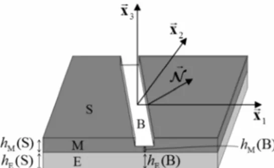
Fig. 2 M–K analysis for a bilayer (current geometry and band orientation)
• h0 ðSÞ and h
M(S): initial and current thickness, respectively,
of the metal layer outside the band.
• h0 ðBÞ and hE(B): initial and current thickness, respectively,
of the elastomer layer inside the band.
• h0 ðSÞ and hE(S): initial and current thickness, respectively,
of the elastomer layer outside the band.
band orientation, then localized necking is detected. The associ- 0 0
ated angle θ corresponds to the orientation of the localization band, while the associated major strain E11 corresponds to the
localization limit strain.
Initial imperfection approach
Note that hEðSÞ and hE(S) are equal to hEðBÞ and hE(B),
respectively.
On the basis of these notations, the initial geometric imper- fection ratio ξ0 (corresponding to the metal layer only) can be
defined as h0 ðBÞ Theoretical equations ξ0 ¼ 1− M h0 ðSÞ ð37Þ
It has been experimentally observed that there are at least three main failure modes for thin substrate-supported metal layers: the plastic strain localization of the metal layer under biaxial stretching, the development of damage in the metal layer, and the buckling and the delamination under compression (see Refs. [22–24]). As has been discussed in the introduction, the second and third failure modes (namely, damage, buckling and delamination between layers) are not the matter of the current contribution, where the main focus is restricted to the prediction
The M–K analysis is governed by four main sets of equa-tions, which are specified in what follows:
• As a consequence of the perfect adherence between the
metal and the elastomer layer, the following equalities between the in-plane velocity gradients in the metal layer and their counterparts in the elastomer layer are satisfied:
GPS PS PS
of the inception of localized necking in the bilayer. Hence, to M ðBÞ ¼ GE ðBÞ ¼ G
GM ðSÞ ¼ GE ðSÞ ¼ G ðBÞ
ðSÞ ð38Þ
PS PS PS
accurately model this problem by using the imperfection ap- proach (called hereafter M–K analysis for the sake of brevity), it is more convenient to introduce the initial geometric imperfec-tion in the form of a band in the metal layer (Fig. 2). The introduction of this imperfection will ultimately trigger the ini- tiation and development of localized necking in the whole bi- layer. Note that this choice of introducing the initial imperfec- tion in the metal layer has been followed and discussed earlier by Xue and Hutchinson (see, e.g., [12, 13]).
To clearly develop the equations of the M–K analysis related to the metal/elastomer bilayer, the following notations are adopted:
When the adherence between the two layers is not perfect, the above equalities between the in-plane velocity gradients in the metal and elastomer layers are not satisfied. In this case, the beneficial effect of necking retardation due to the elasto- mer layer is reduced to some extent, which should be propor- tional to the extent of surface debonding.
• The kinematic compatibility condition between the band
and the uniform zone (i.e., outside the band): this condi-tion requires the displacement increments to be continu-ous across the band, and it is mathematically expressed as
• h0 ðBÞ and h
M(B): initial and current thickness,
respec-tively, of the metal
PS
→
ð39Þ N
C l Ν˙ E ðBÞ ¼ LPSðBÞ : GPSðBÞ Ν˙ M ðBÞ ¼ LPSðBÞ : GPSðBÞ; Ν˙ M ðSÞ ¼ LPSðSÞ : GPSðSÞ; → Ν˙ E ðSÞ ¼ LPSðSÞ : GPSðSÞ → → → → → → l E → → →
• The equilibrium balance across the interface between the l
→: PSl
→
PS PS → PS
\
band and the homogeneous zone:
l l →∞⇔det N l l : L ðBÞ: N →0 ð46Þ → PS P S
PS \ Comparing the above equation with the bifurcation
criteri-N : hMðBÞ Ν˙ M ðBÞ þ hEðBÞ Ν˙ E ðBÞ 40Þ on given by Eq. (31), it is reasonable to expect that the limit
→
PS PS PS
\ ð
¼ N : hMðSÞ Ν˙ M ðSÞ þ hEðSÞ Ν˙ E ðSÞ
• The behavior law of both the metal and the elastomer layer, restricted to the plane dimension, inside and outside the band, respectively: these constitutive equations are expressed in the following generic form:
PS M PS PS ð41Þ M PS E
By inserting the constitutive relations (41) into the equilib- rium eq. (40), this latter becomes
strains predicted by the initial imperfection approach tend to those obtained by the bifurcationtheory when the initial im- perfection ratio ξ0 tends towards zero. This observation will be
verified in BPrediction results^ Section on the basis of various numerical predictions.
Algorithmic aspects
For each strain-path ratio ρ, and each initial band orientation θ0, the equations that govern the M–K analysis are
incremen-tally integrated over each time increment. Indeed, by analyz-ing Eq. (45), it can be seen that the main incremental unknown
:
of the M–K approach is the jump vector CPS. This jump vector
is determined at the end of the time increment by using the fixed point iterative method. For each loading case (i.e., a given strain-path ratio ρ and a given initial band orientation θ0), the computations are conducted until the norm of the jump
: → PS N PS: (h MðBÞ LPSðBÞ þ hEðBÞ LPSðBÞ )
: GPSðBÞ vector C increases abruptly. For the complete details on the
M E
PS ) ð42Þ numerical and algorithmic aspects regarding the M–K
ap-proach, the reader may refer to [14]. ¼ N : (hMðSÞ LPSðSÞ þ hEðSÞ LPSðSÞ
: GPSðSÞ
M E
In other words, Eq. (42) is equivalent to: N PS: LPS
ðBÞ : GPSðBÞ ¼ N PS: LPS
ðSÞ : GPSðSÞ ð43Þ
Prediction results
where LPS(B) and LPS(S) are defined by the following relations: LPSðBÞ ¼ hMðBÞ LPSðBÞ þ hEðBÞ LPSðBÞ
Material and geometric data
Several studies, mainly based on some statistical techniques,
M E 44Þ
LPSðSÞ ¼ hMðSÞ LPSðSÞ þ hEðSÞ LPSðSÞ ð have been carried out in the literature to evaluate the minimum
M E
number of grains that should be used to ensure the represen-Combining the compatibility condition (39) and the
equi-librium eq. (43), one can derive the following expression for
:
the jump vector CPS:
: CPS ¼
tativeness of the volume element. These studies reveal that the obtained results may depend on the boundary conditions ap- plied on the polycrystalline aggregates (periodic boundary conditions….) as well as on the degree of anisotropy of the studied single crystals. In most references (see, for instance,
→ N PS: LPSðBÞ: N \−1 → PS N \
PS: (LPSðSÞ−LPSðBÞ) : GPSðSÞ Refs. [25, 26]), the number of grains required to ensure the
representativeness of the volume element does not exceed ð45Þ
From the above equations (see, e.g., Eq. (39)), it is clear that the localiza:tion of deformation occurs when the magni-tude of vector CPS becomes very large, which means that the
velocity gradient in the band GPS(B) becomes very large as compared to that in the safe zone GPS(S). In such a situation, the deformation concentrates much more rapidly in the imper- fection zone than in the safe zone. A: natural outcome from
1000. Accordingly, we have chosen a polycrystal with 2000
grains, considering that this number is sufficient to generate a volume element representative of the studied sheets. Indeed, from a variety of numerical experiments, we have observed that beyond 2000 grains, the response of the
polycrystalline aggregate representing the metal layer remains almost un- changed. The initial texture corresponding to this aggregate is generated randomly (see Fig. 3), in such a way that it is orthotropic with respect to the rolling and transverse
direc-tions. It is widely recognized that the initial crystallographic
→ →
when N PS: LPS
M
M 1221
E
E E 1221
RD 1111, 1122 and 1221) of the tangent moduli of both layers
for the uniaxial tensile state (ρ = −0.5) and the equibiaxial tensile state (ρ = 1). These evolutions are shown in Fig. 4. From this figure, one can easily observe that the different components of LPS steadily decrease for both strain paths investigated (especially for the equibiaxial tensile state). One particularly observes that the shearing component LPS is
TD
Fig. 3 Initial crystallographic texture of the studied polycrystalline aggregate: {111} pole figure
the predicted FLDs [27]. Initially, all of the grains are assumed to have the same volume fraction. We also assume that the adopted polycrystalline aggregate is representative of the stud- ied metal sheet. As plastic strain localization occurs at rela- tively large strains, the values of the predicted limit strains are almost unaffected by the elastic behavior. This justifies the consideration of simple isotropic elastic behavior in the cur- rent study.
The material parameters of the single crystals are given in Table 1. They are the same as those used in [27].
The shear modulus of the elastomer layer is set to 22 MPa. This choice is based on data for polyurea [28]. To investigate the impact of the addition of the elastomer substrate on the formability of the bilayer, three values of the ratio of elastomer initial thickness to metal initial thickness are considered. The values taken for this ratio (denoted R in the subsequent simu- lation results) are: 0 (which corresponds to a freestanding metal layer), 1 and 2.
Bifurcation theory predictions
The predictions obtained by applying the bifurcation theory are presented and discussed in the current Section.
Before studying the effect of the addition of the elastomer substrate on the formability of the bilayer, we first analyze the evolution of three representative components (components
significantly reduced during the deformation and becomes very small. This observation is a natural outcome of the multi-slip character of crystal plasticity, which leads to the formation of vertices at the current points of the Schmid yield surfaces of single crystals. The reduction of these shearing components is the main destabilizing factor responsible for bifurcation, thus promoting early plastic strain localization (see, e.g., [29, 30]). A correlation can be easily established between the evolution of the shearing components of the tan- gent modulus and the corresponding limit strains predicted by bifurcation theory. It is worth noting that, when a smooth yield function is used, the shearing components of the tangent mod- ulus keep practically a constant magnitude during the defor- mation (see, e.g., [14]). Contrary to the metal layer, the shear- ing component of the tangent modulus LPS corresponding to the elastomer layer continuously increases during the defor- mation, as demonstrated in Fig. 4c and d. Note that this result is valid for the whole range of strain paths, and is not restricted to the particular strain paths investigated in Fig. 4. Considering the evolution of the shearing component LPS , one can conclude that localized necking can never occur in the elastomer layer alone. In the same way, one may also expect a beneficial effect (in terms of retardation of localized necking) from the addition of an elastomer substrate.
It may also be noted that the components of LPS evolve smoothly during the deformation, in contrast to the compo-nents of LPS. Indeed, the tangent modulus LPS of the metal
M M
layer is derived from the tangent moduli of the different con-stituent grains, using the averaging rule given by Eq. (4). In the current micromechanical constitutive modeling, the grains deform freely and the interactions between the different grains are obviously neglected. Consequently, the microscopic tan- gent modulus differs significantly from one grain to another, thus exhibiting high contrast in its components due to texture evolution. This high contrast results in a rather complex evo- lution for the components of the macroscopic tangent modu- lus, as demonstrated in Fig. 4a and b.
The effect of adding an elastomer substrate on the evolu- tion of the minimum of the cubic root of the determinant of the→ →
Table 1 Material parameters of the single crystals that make up the polycrystalline aggregate representative of the metal layer
Elasticity Hardening
acoustic tensor N PS:LPS
: N PS, over all possible band orien-
tations, is illustrated in Fig. 5. The onset of strain localization is predicted when this minimum reaches 0, as defined by the bifurcation criterion (31). Four representative strain paths are
E [GPa] ν τ0 [MPa] h0 [MPa] n
65 0.3 40 390 0.35
considered in this figure: ρ = −0.5, ρ = 0, ρ = 0.5, and ρ = 1. By comparing the different evolutions displayed in Fig. 5, one can clearly observe that the presence of the elastomer layer
E L L L L L L LPS E ijkl L L L L L L
Fig. 4 Evolution of three
PS L
PS PS
representative components of LM and LPS for two different strain paths (ρ = −0.5 and ρ = 1): a Metal layer (ρ = −0.5); b Metal layer (ρ = 1); c Elastomer layer (ρ = −0.5); d Elastomer layer (ρ = 1) 15000 10000 5000 M ijkl (MPa) = PS M 1111 PS M 1122 PS M 1221 8000 6000 4000 2000 LM ijkl (MPa) = PS M 1111 PS M 1122 PS M 1221 0 0.0 0.3 0.6 0.9
(a)
E ijkl (MPa) 0 0.0 0.3 0.6 0.9(b)
LPS (MPa) 150 150 = 100 50 PS E 1111 PS E 1122 PS E 1221 100 50 PS E 1111 PS E 1122 PS E 1221 0 0.0 0.3 0.6 0.9(c)
0 0.0 0.3 0.6 0.9(d)
substantially retards the occurrence of strain localization. This result is expectable considering the evolution of the different components of LPS and LPS investigated in Fig. 4. This
neck-linearly with the initial thickness ratio R, for the different strain paths considered, except in the case ρ = −0.5, where the limit strain increases more rapidly. The same trends have been
ob-M E
ing retardation, due to the addition of the elastomer substrate, is particularly clear in Fig. 5a, where bifurcation is still not detected for the thickness ratio R = 2, while the computations are stopped at a strain value of E11 = 1.
The effect of the elastomer substrate on necking retardation for the whole range of strain paths (ρ ∈ [−1/2, 1]) is shown in Fig. 6. This figure, confirms the preliminary results obtained in Fig. 5: namely, the addition of an elastomer layer allows shifting the FLD upwards, especially in the negative range of strain paths, and thus a significant enhancement in the ductility of the bilayer.
Figure 7 provides additional details and better explains the effect of the relative thickness R of the elastomer layer on the ductility limit of the bilayer. In this figure, the beneficial effect of the thickness ratio R on the enhancement of ductility of the bilayer is confirmed once again. From this figure, it is clearly shown that the limit strain E11 increases slowly and almost
tained when the flow theory of plasticity is used (instead of the micromechanical Taylor model) to model the mechanical be- havior of the metal layer, as demonstrated in [14]. Also, fur- ther relevant details and explanations on the evolution of the limit strain, as a function of the initial thickness ratio R, for various strain paths are provided in [14].
M–K analysis predictions
In this Section, the formability of both the freestanding metal layer and the metal/elastomer bilayer is predicted by using the initial imperfection approach. The results of this Section may be viewed as an extension of the results reported in Fig. 6. In the different simulations, which will be presented in the cur- rent Section, two different values for the initial geometric imperfection ratio ξ0 are used: 10−3 and 10−2. Figure 8
Fig. 5 Effect of adding an elastomer substrate on the evolution of the minimum of the cubic root of the determinant of the acoustic tensor as a function of E11: a ρ = −0.5; b ρ = 0; c ρ = 0.5; d ρ = 1 400 300 Min PS det PS .LPS . FM 1/3 PS 400 300 Min PS det PS .LPS . 1/3 PS 200 100 0 BL (R 1) BL (R 2)
E
11 200 100 0 FM BL (R 1) BL (R 2)E
11 0.0 0.3 0.6 0.9 -100 0.0 0.3 0.6 0.9 -100(a)
(b)
400 Min PS det PS .LPS . 1/3 PS 400 Min PS det PS .LPS . 1/3 PS 300 200 100 0 FM BL (R 1) BL (R 2)E
11 300 200 100 0 FM BL (R 1) BL (R 2)E
11 0.0 0.3 0.6 0.9 0.0 0.3 0.6 0.9 -100 -100(c)
(d)
1.0 0.8 0.6 0.4 0.2 0.0E
11FM
BL (R
)
BL (R 2)
E
22illustrates the effect of the addition of an elastomer layer on the formability of the bilayer, as predicted by the initial im- perfection approach. The results of this figure confirm the observations made in the previous Section, where the bifur- cation theory has been used: namely, the elastomer substrate allows the formability of the bilayer to be enhanced. This observation is common to both initial imperfection ratios (namely, ξ0=10−3 and ξ0=10−2). It is also shown that the effect
of the elastomer substrate is more significant in the range of negative strain paths.
The limit strains obtained by applying the bifurcation anal- ysis set an upper bound to those yielded by the M–K ap-proach. Indeed, Fig. 9 demonstrates that the FLDs predicted by the M–K approach tend towards the FLD predicted by bifurcation analysis when the initial imperfection ratio ξ0
-0.4 -0.2 0.0 0.2 0.4
Fig. 6 Effect of the elastomer substrate on the improvement of the formability of the bilayer (predictions based on bifurcation theory)
tends to zero. In other words, the effect of an initial imper-fection is essentially to shift the FLD downwards. This ob- servation is natural considering the similarity of the
1.0 0.8 0.6 0.4 0.2 0.0
E
11 dependent approaches (see [31, 32]) or rate-independentcrystal plasticity modeling (see [27]). The results obtain- ed in the present study are in agreement with those re- ported in the above literature studies.
Computation times
The numerical tools pertaining to the current study have been implemented using the multi-paradigm numerical computing environment Matlab (R2015). This choice is motivated by the fact that this software offers efficient and powerful tools and functionalities in order to optimize the numerical
implemen-R
tation. The simulations presented in this paper are all per-formed on a personal computer with 2.00 GHz of CPU fquency and 6.00 Go of RAM memory. The CPU time
re-Fig. 7 Effect of the relative thickness of the elastomer layer on the enhancement of ductility of the bilayer (predictions based on bifurcation theory)
mathematical formulations of the two approaches (M–K and bifurcation): if the amount of initial imperfection is set to 0 in the imperfection model, the problem reduces to the bifurca- tion analysis. This conclusion is valid for a freestanding metal layer as well as for an elastomer-supported metal layer.
As demonstrated in Fig. 9, an increase in the amount of initial imperfection leads to a reduction in the limit strains. To further illustrate this feature, Fig. 10 shows the evolution of the limit strain E11 as a function of the
initial imperfection size ξ0 for different strain-path ratios
ρ. Note that, in this figure, the limit strain corresponding to the abscissa ξ0 = 0 is the one predicted by the bifur-
cation criterion. It can be clearly seen that the limit strain decreases when the initial imperfection increases, for all strain-path ratios ρ investigated. This dependence of the predicted limit strains on the amount of initial imperfec- tion has been previously studied using multiscale
rate-quired for the prediction of a single FLD by using the bifur- cation theory (resp. the initial imperfection approach) is about 6400 s (resp. 60,000 s). Of course, the evaluation of these computation times is indicative and it is strongly dependent on a number of numerical parameters and choices (the incre- ment for the strain-path ratio, the increment selected for the band orientation angle when the initial imperfection approach is used, the size of the strain step used to integrate the con- stitutive equations corresponding to both the metal and elas- tomer layers, etc.).
Concluding remarks
A numerical tool to predict the onset of localized necking in substrate-supported metal layers has been developed in this paper. In this tool, the mechanical behavior of the metal (resp. elastomer) layer is modeled by the full-constraint Taylor multiscale model (resp. neo-Hookean hyperelastic model). The layers composing the bilayer remain bounded and are
Fig. 8 Effect of the elastomer substrate on the improvement of the formability of the bilayer (predictions based on the M–K analysis): a ξ0 = 10−3; b ξ0 = 10−2 1.0 0.8
E
11 FM 1.0 0.8E
11 0.6 0.4 BL (R ) BL (R 2) 0.6 0.4 FM BL (R 1) BL (R ) 0.2 0.0E
22 0.2 0.0E
22 -0.4 -0.2 0.0 0.2 0.4(a)
-0.4 -0.2 0.0 0.2 0.4(b)
E
E
Fig. 9 Effect of the initial geometric imperfection on the shape and the level of the FLDs of the bilayer: a FM; b BL (R = 1); c BL (R = 2) 1.0 0.8
E
11 FM 1.0 0.8E
11 BL (R 1) Bifurcation 0.6 M ( 10 3) M ( 10 2 ) 0.4 Bifurcation 0.6 M ( 10 3 ) M ( 10 2 ) 0.4 0.2 0.0 E22 0.2 0.0E
22 -0.4 -0.2 0.0 0.2 0.4 0.6(a)
1.0 11 0.8 -0.4 -0.2 0.0 0.2 0.4(b)
BL (R 2) 0.6 0.4 Bifurcation M ( 10 3) M ( 10 2) 0.2 0.0E
22 -0.4 -0.2 0.0 0.2 0.4(c)
11 0.6 0.4 Bilayer (R 1)such that material damage does not occur prior to localized necking. Hence, other failure modes than localized necking (such as damage, interfacial delamination) are not considered in this contribution. The constitutive modeling of the bilayer is coupled with two strain localization criteria in order to predict the associated limit strains. These localized necking criteria consist of the bifurcation theory and the initial imper- fection approach. From the numerical predictions obtained by applying this tool, three main conclusions can be drawn: 0.2
0.0 0
0.000 0.003 0.006 0.009
Fig. 10 Evolution of the limit strain E11, as a function of the initial
imperfection ratio ξ0, for different strain-path ratios ρ
• The presence of an elastomer layer substantially increases the level of the limit strains for the bilayer.
• The shape and the level of the predicted FLDs are signif-icantly influenced by the amount of initial geometric im-perfection, which is assumed to initiate in the metal layer. • The limit strains of the bilayer predicted by bifurcation theory set an upper bound to those yielded by the M–K approach.
It is worth noting that the use of the Taylor multiscale model in the current work has been mainly motivated by its simplicity and its efficiency. Indeed, with this scale-transition scheme, all the numerical results (for both freestanding metal layers and metal/elastomer bilayers), as well as the associated FLDs are obtained within reasonable running times. Also, we believe that the observed trends and the associated conclu- sions are valid whatever the multiscale scheme used.
From a practical perspective, the numerical tools de- veloped in the current investigations can be used, in an industrial context, to provide guidelines and assistance in the design of new generations of electronic devices with improved ductility.
Compliance with ethical standards
Conflict of interest The authors declare that they have no conflict of interest.
References
1. Tekoğlu C, Hutchinson JW, Pardoen T (2015) On localization and void coalescence as a precursor to ductile fracture. Phil Trans R Soc A 373:2038
2. K. Saanouni (2012) Damage mechanics in metal forming. Advanced modeling and numerical simulation. ISTE/Wiley, London
3. Keeler SP, Backofen WA (1963) Plastic instability at fracture in sheets stretched over rigid punches. Trans ASM 56:25
4. Goodwin GM (1968) Application of the strain analysis to sheet metal forming in the press shop. Metallurgia Italiana 60:767 5. Kotkunde N, Krishna G, Shenoy SK, Gupta AK, Singh SK (2015)
Experimental and theoretical investigation of forming limit diagram for Ti-6Al-4 V alloy at warm condition. Int J Mater Form 10(2): 255–266. https://doi.org/10.1007/s12289-015-1274-3
6. Strano M, Colosimo BM (2006) Logistic regression analysis for experimental determination of forming limit diagrams. Int J Mach Tool Manu 46(6):673–682. https://doi.org/10.1016/j.ijmachtools. 2005.07.005
7. Rice JR (1976) The localization of plastic deformation. The local- ization of plastic deformation. In: Koiter W T (ed) Theoretical and Applied Mechanics (Proceedings of the 14th International Congress on Theoretical and Applied Mechanics, Delft, vol 1. North-Holland Publishing Co., Amsterdam, pp 207–220 8. Marciniak Z, Kuczynski K (1967) Limit strains in the processes of
stretch-forming sheet metal. Int J Mech Sci 9(9):609–620. https:// doi.org/10.1016/0020-7403(67)90066-5
9. Chiu SL, Leu J, Ho PS (1994) Fracture of metal‐polymer line struc- tures. I. Semiflexible polyimide. J Appl Phys 76(9):5136–5142.
https://doi.org/10.1063/1.357227
10. Hommel M, Kraft O (2001) Deformation behavior of thin copper films on deformable substrates. Acta Mater 49(19):3935– 3947. https://doi.org/10.1016/S1359-6454(01)00293-2
11. Alaca BE, Saif MTA, Sehitoglu H (2002) On the interface debond at the edge of a thin film on a thick substrate. Acta Mater 50(5): 1197–1209. https://doi.org/10.1016/S1359-6454(01)00421-9
12. Xue ZY, Hutchinson JW (2007) Neck retardation and enhanced energy absorption in metal–elastomer bilayers. Mech Mater 39(5): 473–487. https://doi.org/10.1016/j.mechmat.2006.08.002
13. Xue ZY, Hutchinson JW (2008) Neck development in metal/ elastomer bilayers under dynamic stretchings. Int J Solids Struct 45(13):3769–3778. https://doi.org/10.1016/j.ijsolstr.2007.10.006
14. Ben Bettaieb M, Abed-Meraim F (2015) Investigation of localized necking in substrate-supported metal layers: Comparison of bifur- cation and imperfection analyses. Int J Plast 65:168–190. https:// doi.org/10.1016/j.ijplas.2014.09.003
15. Rudnicki JW, Rice JR (1975) Conditions for the localization of 937 deformation in pressure-sensitive dilatant materials. J. Mech. 938 Phys. Solids 23(6):371–394. https://doi.org/10.1016/0022-5096(75)90001-0
16. J.W. Hutchinson, K.W. Neale (1978) Sheet Necking- II. Time-Independent Behavior. In: Koistinen DP, Wang NM (eds) Mechanics of sheet metal forming. Plenum Publishing Corporation, New York, pp 127–153
17. Borja RI, Wren JR (1993) Discrete micromechanics of elastoplastic crystals. Int J Numer Methods Eng 36(22):3815–3840. https://doi. org/10.1002/nme.1620362205
18. Akpama HK, Ben Bettaieb M, Abed-Meraim F (2016) Numerical integration of rate-independent BCC single crystal plasticity models: comparative study of two classes of numerical algorithms. Int J Numer Methods Eng 108(5):363–422.
https://doi.org/10.1002/ nme.5215
19. Anand L, Kothari M (1996) A computational procedure for rate- independent crystal plasticity. J Mech Phys Solids 44(4):525–558.
https://doi.org/10.1016/0022-5096(96)00001-4
20. Hunter SC (1979) Some exact solutions in the theory of finite elas-ticity for incompressible neo-Hookean materials. Int J Mech Sci 21(4):203–211. https://doi.org/10.1016/0020-7403(79)90064-X
21. Hutchinson JW, Neale KW, Needleman A (1978) Sheet Necking- I. Time-independent behavior. In: Koistinen DP, Wang N-M (eds) Mechanics of sheet metal forming, Plenum Publishing Corporation, New york, pp 111–126
22. Changchun Z, Hongpo Z, Jianqiang H, Wanzhao C (2003) MEMS Devices Technol. 10 (30)(2003)
23. McShane GJ, Stewart C, Aronson MT, Wadley HNG, Fleck NA, Deshpande VS (2008) Dynamic rupture of polymer–metal bilayer plates. Int J Solids Struct 45(16):4407–4426. https://doi.org/10. 1016/j.ijsolstr.2008.03.017
24. Men Y, Wang S, Jia H, Wu Z, Li L, Zhang C (2013) Experimental study on tensile bifurcation of nanoscale Cu film bonded to poly-ethylene terephthalate substrate. Thin Solid Films 548:371–376.
https://doi.org/10.1016/j.tsf.2013.08.090
25. Szyndler J, Madej L (2014) Effect of number of grains and bound-ary conditions on digital material representation deformation under plane strain. Arch Civ Mech Eng 14(3):360–369. https://doi.org/10. 1016/j.acme.2013.09.001
26. Houdaigui FE, Forest S, Gourgues A-F, Jeulin D (2007) On the size of the representative volume element for isotropic elastic polycrys-talline copper. In: Bai Y (ed) IUTAM Symposium on mechanical behavior and micro-mechanicsof nanostructured materials. Springer, Dordrecht pp 171–180
27. Yoshida K, Kuroda M (2012) Comparison of bifurcation and im-perfection analyses of localized necking in rate-independent poly- crystalline sheets. Int J Solids Struct 49(15-16):2073–2084. https:// doi.org/10.1016/j.ijsolstr.2012.04.010
28. Amirkhizi AV, Isaacs J, McGee J, Nemat-Nasser S (2006) An experimentally-based viscoelastic constitutive model for polyurea, including pressure and temperature effects. Philos Mag 86(36): 5847–5866. https://doi.org/10.1080/14786430600833198
29. Hutchinson JW (1970) Elastic-Plastic Behaviour of Polycrystalline Metals and Composites. Proc R Soc Lond A 319(1537):247–272.
https://doi.org/10.1098/rspa.1970.0177
30. Yoshida K, Brenner R, Bacroix B, Bouvier S (2009) Effect of reg-ularization of Schmid law on self-consistent estimates for
rate-independent plasticity of polycrystals. Eur J Mech – A/Solids 28(5): 905–915. https://doi.org/10.1016/j.euromechsol.2009.05.001
31. Zhou Y, Neale KW (1995) Predictions of forming limit diagrams using a rate-sensitive crystal plasticity model. Int J Mech Sci 37(1): 1–20. https://doi.org/10.1016/0020-7403(94)00052-L
32. Signorelli JW, Bertinetti MA, Turner PA (2009) Predictions of forming limit diagrams using a rate-dependent polycrystal self-consistent plasticity model. Int J Plast 25(1):1–25. https://doi.org/ 10.1016/j.ijplas.2008.01.005