Cooperative Diversity in Wireless Networks:
Algorithms and Architectures
by
J. Nicholas Laneman
B.S. E.E., Washington University (1995) B.S. C.S., Washington University (1995)
S.M. E.E., Massachusetts Institute of Technology (1997)
Submitted to the Department of Electrical Engineering and Computer Science in partial fulfillment of the requirements for the degree of
Doctor of Philosophy in Electrical Engineering at the
MASSACHUSETTS INSTITUTE OF TECHNOLOGY September 2002
@
Massachusetts Institute of Technology 2002. All rights reserved.IN
Author ... . . . .... . . . . ....
Deg tment of Electrical Engineering and Computer Science August 1, 2002 I A Certified by ...
.. . .. . . .
dregory
W. Wornell Professor Thesis Supervisor2
Accepted by ...Chairman, Department Committee on
Ar'hur C. Smith Graduate Students
BARKER
MASSACHUSETTS INSTITUTE OF TECHNOLOGYNOV
18 2002
V/
0
Cooperative Diversity in Wireless Networks:
Algorithms and Architectures
by
J. Nicholas Lanenian
Submitted to the Department of Electrical Engineering and Computer Science on August 1, 2002, in partial fulfillment of the
requirements for the degree of
Doctor of Philosophy in Electrical Engineering
Abstract
To effectively combat multipath fading across multiple protocol layers in wireless networks, this dissertation develops energy-efficient algorithms that employ certain kinds of cooper-ation among terminals, and illustrates how one might incorporate these algorithms into various network architectures. In these techniques, sets of terminals relay signals for each other to create a virtual antenna array, trading off the costs-in power, bandwidth, and complexity-for the greater benefits gained by exploiting spatial diversity in the channel. By contrast, classical network architectures only employ point-to-point transmission and thus forego these benefits.
After summarizing a model for the wireless channel, we present various practical coop-erative diversity algorithms based upon different types of relay processing and re-encoding, both with and without limited feedback from the ultimate receivers. Using information-theoretic tools, we show that all these algorithms can achieve full spatial diversity, as if each terminal had as many transmit antennas as the entire set of cooperating terminals. Such diversity gains translate into greatly improved robustness to fading for the same transmit power, or substantially reduced transmit power for the same level of performance. For example, with two cooperating terminals, power savings as much as 12 dB (a factor of sixteen) are possible for outage probabilities around one in a thousand. Finally, we discuss how the required level of complexity in the terminals makes different algorithms suitable for particular network architectures that arise in, for example, current cellular and ad-hoc networks.
Thesis Supervisor: Gregory W. Wornell Title: Professor
Acknowledgments
Numerous people have supported me during the development of this dissertation, and my graduate experience more generally. A few words' mention here cannot adequately capture all my appreciation.
My advisor, Greg Wornell, deserves particular attention and many, many thanks. He has helped me reach several milestones as an academic, and prepared me to reach many more. I want to thank him for his inquisitiveness, insight, and inspiration. I have benefited tremendously from his countless efforts and undaunting dedication to the intellectual and personal growth of his graduate students. He has left an indelible mark.
I would also like to thank the other members of my dissertation committee, Hari Bal-akrishnan, Muriel Medard, and David N.C. Tse, for many useful interactions and for con-tributing their broad perspective in refining the ideas in this dissertation.
The financial support of the National Science Foundation, the U.S. Army Research Laboratory, and the Hewlett-Packard Company, through the HP-MIT Alliance, are also gratefully acknowledged.
The Digital Signal Processing Group (DSPG) has been a truly enriching and collegial environment for me as a graduate student, one I can only hope to emulate in the future. I thank Al Oppenheim and Greg Wornell for continually attracting such extraordinary students. Of the many who have contributed significantly to my M.I.T. experience over the years, I offer a word of particular appreciation to several from more recent years. Thanks go to Richard Barron, Aaron Cohen, Stark Draper, Emin Martinian, and Wade Torres for intense technical discussions, photo critiques, Toscanini runs, Ishmael debates, and more than a few basketball games; thanks also to Yonina Eldar and Andrew Russell for markedly non-technical discussions.
Of many other friends and colleagues, I want to thank Brian Hearing and Steve Ludwick for a number of well-timed and unforgettable hiking trips. Thanks also go to Sae-Young Chung, Thierry Klein, and Edmund Yeh for playing foosball matches instead of doing research at Bell Labs, and to Jay Gelman for playing golf instead of doing research at Lincoln Labs.
Never having had a brother, I have sought out several replacements through the years. None have been better to me than Giovanni Aliberti. I want to thank Vanni for his computer hacking and general wisdom, for taking me under his wing, and for making Mishie and I part of his family. Along with Darlete, Victor, Clarissa, and Martin, he makes leaving Boston especially bittersweet.
As always, I thank my family for inspiring me to pursue an academic career: Mom and Dad for giving the first lectures I attended, and Jenny and Jill for patiently listening to my earliest tutorials. I thank them, and the rest of my extended family, for "letting me do what I needed to do." Their encouragement, support, and understanding through these many years have meant more I can ever express. I GOT IT DONE!
Last, my most tender and sincere thanks go to my loving wife, Mishie. Aside from perhaps myself, no one has been more impacted by this dissertation and the latter years of my graduate program. I want to thank her for supporting me (and the two of us) in innumerable ways. This dissertation is not good enough to dedicate to her, but the one we are writing together will be.
. And what's the good of diversity?"
"I don't know. It's certainly more . . . interesting." - from Ishmael, by Daniel
Quinn
Contents
1 Introduction
1.1 Cooperative Diversity . . . . 1.2 Motivating Example . . . . 1.3 Layered Architectures and Cross-Layer Design . . . . 1.4 Outline of the Dissertation . . . .
2 High-Level System Model
2.1 Radio Hardware and Constraints . . . . 2.2 Wireless Channel Impairments . . . . 2.2.1 Multipath Propagation: Path-Loss and Fading 2.2.2 Interference and Other Issues . . . . 2.3 Network Architectures . . . . 2.3.1 Prevalent Wireless Network Architectures . . . 2.3.2 New Architectures Incorporating Cooperation
3 Background and Related Literature
3.1 Relay Channels and Extensions . . . . 3.2 Fading Channel Capacity . . . . 3.2.1 Shannon Capacity . . . . 3.2.2 Capacity-vs.-Outage . . . . 3.2.3 Average Capacity . . . . 3.3 Multi-Antenna Systems . . . . 3.3.1 Fundamental Performance Limits . . . . 3.3.2 Space-Time Codes . . . . 3.4 W ireless Networks . . . . 19 19 20 22 24 27 29 30 30 33 34 35 37 41 . . . . 42 . . . . 45 . . . . 45 . . . . 48 . . . . 49 . . . . 49 . . . . 52 . . . . 54 . . . . 5 4
3.4.1 Infrastructure Networks 54
3.4.2 Ad-Hoc Networks . . . .
4 Cooperative Diversity with Full Temporal Diversity 4.1 Model and Definitions ...
4.1.1 Block Diagram ...
4.1.2 Parameterization . . . . 4.1.3 Special Cases and Coding Strategies . . . . 4.1.4 D efinitions . . . . 4.2 Converse: Outer Bound on the Capacity Region . . . 4.3 Achievability: Inner Bounds on the Capacity Region . 4.3.1 Non-Cooperative Transmission . . . . 4.3.2 Decode-and-Forward Transmission . . . . 4.4 Rayleigh Multipath Fading . . . .
5 Cooperative Diversity without Temporal Diversity
55 59 . . . . 6 0 . . . . 6 1 . . . . 6 2 . . . . 6 3 . . . . 6 5 . . . . 6 8 . . . . 7 1 . . . . 7 1 . . . . 7 4 . . . . 7 5 79 5.1 System M odel . . . . 81 5.1.1 M edium Access . . . . 82
5.1.2 Equivalent Channel Models . . . . 83
5.1.3 Parameterizations . . . . 85
5.2 Cooperative Transmission Protocols . . . . 86
5.2.1 Fixed Protocols . . . . 87
5.2.2 Adaptive Protocols . . . . 88
5.2.3 Protocols with Limited Feedback . . . . 89
5.3 Outage Behavior . . . . 90
5.3.1 Direct Transmission . . . . 91
5.3.2 Fixed Protocols . . . . 92
5.3.3 Adaptive Protocols . . . . 94
5.3.4 Bounds for Cooperative Diversity Transmission . . . . 96
5.3.5 Protocols with Limited Feedback . . . . 98
5.4 Discussion . . . . 100
5.4.1 Asymmetric Networks . . . . 100
5.4.2 Symmetric Networks . . . . 104
6 Cooperative Diversity in Networks
6.1 Fully Cooperative Networks . . . . 6.1.1 System M odel . . . . 6.1.2 Repetition-Based Cooperative Diversity . . . . 6.1.3 Space-Time Coded Cooperative Diversity . . . . 6.1.4 Diversity-Multiplexing Tradeoff . . . . 6.2 Partially Cooperative Networks . . . . 6.2.1 Centralized Partitioning for Infrastructure Networks 6.2.2 Clustering in Ad-Hoc Networks . . . . 6.2.3 Comments on Layering Issues . . . .
7 Conclusions
7.1 Contributions . . . . 7.2 Future Research . . . .
A Coding Theorem for Cooperative Diversity
A .1 D efinitions . . . . A .2 Prelim inaries . . . . A.3 Decode-and-Forward Transmission . . . . A.3.1 Codebook Generation . . . . A .3.2 Encoding . . . . A.3.3 Backwards Decoding . . . . A.3.4 Probability of Error and Achievable Rates . . . .
B Asymptotic CDF Approximations
B.1 Results for Chapter 5 . . . . B.2 Results for Chapter 6 . . . . B.2.1 The Basic Result . . . . B.2.2
B.2.3
Repetition Decode-and-Forward Cooperative Space-Time Coded Cooperative Diversity .
109 . . . . 109 . . . . 112 . . . . 117 . . . . 121 . . . . 126 . . . . 127 . . . . 129 . . . . 135 . . . . 136 139 139 141 145 . . . 145 . . . 147 . . . 148 . . . 149 . . . 150 . . . 151 . . . 152 159 . . . . 159 . . . . 168 . . . . 168 Diversity . . . . 171 . . . . 172
C Mutual Information Calculations
C.1 Amplify-and-Forward Mutual Information . . . . C.2 Input Distributions for Transmit Diversity Bound ...
175 175 176
List of Figures
1-1 Illustration of radio signal transmit paths in an example wireless network with two terminals transmitting information and two terminals receiving
in-form ation . . . . 21
1-2 Layered protocol architecture. . . . . 23
2-1 Block diagram for a wireless network model having four terminals. . . . . . 28
2-2 Radio block diagram . . . . 29
2-3 Discrete-time, baseband-equivalent channel model for signal received by radio
j
31 2-4 Protocol stack for a general layered network architecture. . . . . 352-5 Various relaying configurations that arise in wireless networks: (a) classical relay channel, (b) parallel relay channel, (c) multiple-access channel with relaying, (d) broadcast channel with relaying, (e) interference channel with relaying. . . . . 38
3-1 Block diagrams relating a point-to-point physical array (a) and a multi-user virtual array (b) arising from cooperative diversity transmission. . . . . 50
3-2 Multi-antenna system model. . . . . 51
4-1 Block diagram for a multiple-access channel with cooperative diversity. . . . 61
4-2 Block diagram for a relay channel. . . . . 64
4-3 Illustration of shape of various outer and inner bounds on the capacity region of the Gaussian multiple access channel with cooperative diversity. Here the SNRs take values so,1 = so,2 = 3, and S2,1 = si,2 = 15. . . . . 72
5-1 Illustration of radio signal transmit paths in an example wireless network with two terminals transmitting information and two terminals receiving in-form ation . . . . 81
5-2 Example time-division channel allocations for (a) direct transmission with interference, (b) orthogonal direct transmission, and (c) orthogonal coopera-tive diversity transmission protocols. We focus on orthogonal transmissions of the form (b) and (c) throughout the chapter. . . . . 83
5-3 SNR loss for cooperative diversity protocols (solid) and orthogonal transmit diversity bounds (dashed) relative to the (unconstrained) transmit diversity bound (0 dB ). . . . . 101
5-4 Outage event boundaries for amplify-and-forward (solid) and adaptive decode-and-forward (dashed and dash-dotted) transmission as functions of the re-alized fading coefficient las,r12
between the cooperating terminals. Out-age events are to the left and below the respective outOut-age event bound-aries. Successively lower solid curves correspond to amplify-and-forward with increasing values of |as,r2. The dashed curve corresponds to the outage event for adaptive decode-and-forward when the relay can fully decode, i.e., SNRnormlas,r12
> 2, and the relay repeats, while the dash-dotted curve corre-sponds to the outage event of adaptive decode-and-forward when the relay cannot fully decode, i.e., SNRnormIas,r12 < 2, and the source repeats. Note
that the dash-dotted curve also corresponds to the outage event for direct transm ission. . . . . 103
5-5 Outage probabilities vs. SNRnorm, small R regime, for statistically symmetric networks, i.e., 0 = 1. The outage probability curve for amplify-and-forward transmission was obtained via Monte-Carlo simulation, while the other curves are computed from analytical expressions. The dashed curve corresponds to the transmit diversity bounds in this low spectral efficiency regime. . . . . . 106
5-6 Diversity order A vs. Rnorm for direct transmission and cooperative diversity protocols. . . . . 108
6-1 Illustration of the two-phases of repetition-based and space-time coded coop-erative diversity algorithms. In the first phase, the source broadcasts to the destination as well as potential relays. Decoding relays are shaded. In the second phase, the decoding relays either repeat on orthogonal subchannels or utilize a space-time code to simultaneously transmit to the destination. . 111
6-2 Non-cooperative medium-access control. Example source allocations among
m transmitting terminals across orthogonal frequency channels. . . . . 113 6-3 Repetition-based medium-access control. Example source channel allocations
across frequency and relay subchannel allocations across time for repetition-based cooperative diversity among m terminals. . . . . 114
6-4 Space-time coded medium-access control. Example channel allocations across frequency and time for m transmitting terminals. For source s, 'D(s) denotes the set of decoding relays participating in a space-time code during the second phase. ... ... 114
6-5 Comparison of numeric integration of the outage probability (solid lines) to calculation of the outage probability approximation (6.10) (dashed lines) vs. normalized SNR for different network sizes m = 1, 2, ... , 10. Successively lower curves at high SNR correspond to larger networks. For simplicity of exposition, we have plotted the case of R = 1 b/s/Hz and Ay = 1; more generally the plot can be readily updated to incorporate a model of the network geom etry. . . . . 120
6-6 Comparison of numeric integration of the outage probability (solid lines) to calculation of the outage probability approximation (6.19) (dashed lines) vs. normalized SNR for different network sizes m = 1, 2,... ,10. Successively lower curves at high SNR correspond to larger networks. For simplicity of exposition, we have plotted the case of R = 1 b/s/Hz and Ay = 1; more generally the plot can be readily updated to incorporate a model of the network geom etry. . . . . 124
6-7 Diversity order A(Rnorm) for non-cooperative transmission, repetition-based cooperative diversity, and space-time coded cooperative diversity. As Rnorm -+ 0, all cooperative diversity protocols provide full spatial diversity order m, the number of cooperating terminals. Relative to direct transmission, space-time coded cooperative diversity can be effectively utilized for a much broader range of Rnorm than repetition-coded cooperative diversity, especially as m becom es large. . . . .. . . . . . . 128 6-8 Matching algorithm performance in terms of average outage probability vs.
received SNR (normalized for direct transmission). . . . . 133 6-9 Matching algorithm results for an example network: (a) minimal matching,
(b) greedy matching. Terminals are indicated by circles, and matched termi-nals are connected with lines. . . . . 134 6-10 Clustering with (a) direct transmission and (b) cooperative diversity
trans-m ission . . . . 135
List of Tables
2.1 Form of aj,i[l; k] for a several important channel conditions. . . . . 32
5.1 Summary of outage probability approximations. To capture the salient trade-offs between signal-to-noise ratio SNR, spectral efficiency R b/s/Hz, and di-versity gain of the various protocols, the results are specialized to the case of
Chapter 1
Introduction
Exploding demand for a growing number of wireless applications has fueled significant de-velopment of wireless networks, especially several generations of cellular voice and data networks and, more recently, ad-hoc data networks for wireless computer, home, and per-sonal networking. Radio hardware and wireless services grow more efficient and cost effective as system designers better understand the channel environment and multi-user communi-cations in general, and technological advances in integrated circuits and radio-frequency electronics increasingly allow for more sophisticated signal processing and channel coding algorithms. However, compared to point-to-point links, it seems we are only beginning to understand the fundamental performance limits of wireless networks and practical ways for approaching them. Moreover, given their impact on society as well as other technologies, wireless communications and networking remain important areas of research.
1.1
Cooperative Diversity
Taking advantage of the rich wireless propagation environment across multiple protocol layers in a network architecture offers numerous opportunities to dramatically improve network performance. In this dissertation, we develop an energy-efficient class of cross-layer network algorithms called cooperative diversity that exploit the broadcast nature and inherent spatial diversity of the channel. Through cooperative diversity, sets of wireless terminals benefit by relaying messages for each other to propagate redundant signals over multiple paths in the network. This redundancy allows the ultimate receivers to essentially average channel variations resulting from fading, shadowing, and other forms of interference.
By contrast, classical network architectures only employ a single path through the network and thus forego these benefits.
We develop various cooperative diversity algorithms that have the relays (1) simply amplify what each receives, or (2) fully decode, re-encode, and re-transmit each other's messages. In addition, we evaluate algorithms based upon repetition codes or more general space-time codes, as well as algorithms with and without limited feedback from the ultimate receivers. We demonstrate that cooperative diversity can provide full spatial diversity, as if each terminal had as many transmit antennas as the entire set of cooperating terminals. Such diversity gains translate into greatly improved robustness to fading for the same trans-mit power, or substantially reduced transtrans-mit power for the same level of performance. For example, power savings on the order of 12 dB (a factor of sixteen) are possible for outage probabilities around one in a thousand. Although applicable to any wireless setting, these algorithms are most beneficial when other forms of diversity-such as temporal coding, spread-spectrum, and multi-antenna systems-cannot be exploited.
From an architectural perspective, we illustrate how repetition and space-time coded co-operative diversity are each amenable to different settings. Repetition-based schemes require relatively low complexity in the terminals, but require more complexity in the network for deciding which terminals cooperate in order for the algorithms to be effective; thus, these algorithms are well-suited to infrastructure networks, e.g., cellular, satellite, and certain wireless local area network (LAN) configurations, in which terminals communicate directly to a super-terminal that selects the cooperating groups. To manage complexity in the super-terminal, we use our analytical results to develop a variety of grouping algorithms based upon set partitioning and weighting matching in graphs. By contrast, space-time coded cooperative diversity requires more complexity in the terminals, but readily extends to distributed implementation; thus, these algorithms are well-suited to ad-hoc networks, and especially ad-hoc networks with clusters. We also briefly discuss various layering and other architectural issues.
1.2
Motivating Example
To illustrate the main concepts, consider the example wireless network in Fig. 1-1, in which terminals Ti and T2 transmit to terminals T3 and T4, respectively. This example might
(T2)
Figure 1-1: Illustration of radio signal transmit paths in an example wireless network with two terminals transmitting information and two terminals receiving information.
correspond to a snapshot of a wireless network in which a higher-level network protocol has allocated bandwidth to two users for transmission to their intended destinations or next hops. For example, in the context of a cellular network, T, and T2 might correspond to
terminal handsets and T3 = T4 might correspond to the basestation. As another example,
in the context of a wireless LAN, the case T3 7 T4 might correspond to an ad-hoc
configu-ration among the terminals, while the case T3 = T4 might correspond to an infrastructure
configuration, with T3 serving as an access point. The key property of the wireless medium that allows for cooperative diversity between the transmitting radios is its broadcast na-ture: transmitted signals can, in principle, be received and processed by any of a number of terminals. Thus, instead of transmitting independently to their intended destinations, T and T2 can listen to each other's transmissions and jointly communicate their information.
Although these extra observations of the transmitted signals are available for free (except, possibly, for the cost of additional receive hardware) wireless network protocols often ignore or discard them.
In the most general case, Ti and T2 can share their resources to cooperatively transmit
their information to their respective destinations, corresponding to a wireless multiple-access channel with relaying for T3 = T4, and to a wireless interference channel with relaying for T3 5 T4. At one extreme, corresponding to a wireless relay channel, the transmitting
terminals can focus all their resources, in terms of power and bandwidth, on transmitting the information of T1. In this case, T acts as the "source" of the information, and T2 serves
as a "relay". Such an approach might provide diversity in a wireless setting because, even if the channel quality between T1 and T3 is poor, the information might be successfully transmitted through T2. Similarly, Ti and T2 can focus their resources on transmitting the
To date, these channel models have been only partially addressed in the literature, and mainly within the information theory community. For general memoryless channels, the capacity region without cooperation is known for multiple-access channels, and remains an open problem for interference channels, although several achievable rate regions have been demonstrated [191. Several notions of channel capacity, including Shannon, delay-limited, and information outage capacities, have been treated for wireless multiple-access channels [83, 34, 52]. Multiple-access channels with varying degrees of cooperation between the transmitting terminals have also been examined [88, 91, 89, 901. Reference [17] examines certain relay channels, without specifically addressing wireless channels, and constructs several coding schemes for achieving reliable communication over such channels. Multiple-relay extensions have also been examined [66, 65, 33, 29, 28, 27]. As we will see, our work on cooperative diversity for wireless networks blends many techniques and insights from these references.
Recently, [68, 69, 70] considers cooperative diversity for a wireless multiple-access chan-nel with relaying. The transmitters and receiver employ a two-user generalization of the cooperation scheme developed in [17], and, under the condition that the signal-to-noise ra-tio (SNR) between the transmitting terminals is high, cooperative diversity of this form is shown to enlarge the achievable rate region (including increasing the sum rate for the case in which both the transmitters and receivers possess knowledge of the channel conditions) in ergodic settings, as well as improve outage performance under strict delay constraints or in non-ergodic settings, when compared to the multiple-access channel without cooperative diversity [69, 70]. We develop some new insights for ergodic settings, but the majority of our results are for non-ergodic settings.
1.3
Layered Architectures and Cross-Layer Design
Several key properties of wireless environments make design of wireless networks particularly complex and challenging. First, radio signals experience significant attenuation, called
path-loss, as well as self-interference, called fading, induced by multipath propagation through
a lossy medium. Generally speaking, these channel distortions require increasing power, bandwidth, and receiver complexity to reliably communicate over longer distances. At the same time, radios in a wireless network share a common transmission medium, e.g.,
Application Transport Network Link Medium-Access Control I Physical COMPRESSION FLOW CONTROL ROUTING ARQ LIMIT INTERFERENCE CHANNEL CODING Application iF Transport Network Link Medium-Access Control Physical Wireless Channel
Figure 1-2: Layered protocol architecture.
a fixed amount of wireless spectrum; thus, radio signals are subject to interference from other users in the system as well as from other wireless systems operating in the same spectrum. Tradeoffs among required power, bandwidth, and receiver complexity naturally
arise because of the interference characteristics of the channel.
As a result of this rich channel environment, wireless system designers are presented with many challenges. These include, for example: reliably transmitting information among radio terminals; mitigating severe channel impairments such as multipath fading and interference from other users; efficiently allocating and utilizing resources such as power and bandwidth; scaling algorithms as the number of terminals in the network grows; and supporting a large and ever-growing number of applications, such as voice, data, and multimedia networking. Engineers have historically partitioned solutions to these problems into a stack of proto-col layers, each serving a particular purpose. Fig. 1-2 illustrates these layers, and indicates the functions they usually serve in the wireless setting. As examples, the Medium-Access Control (MAC) Layer conventionally manages interference in the network, and the Physical (PHY) Layer conventionally combats fading with coding, spread-spectrum, and multiple antennas. Layering promotes development of understanding and technology within each
layer; however, different communities often work on problems at the various layers. For ex-ample, the data and computer networking community has developed a variety of standard protocols for flow control in the Transport Layer, routing in the Network Layer, automatic repeat request (ARQ) in the Link Layer, and collision resolution/avoidance in the Medium-Access Control Layer. Traditionally, the communication theory, information theory, and signal processing communities have played a role mainly at the Application Layer in the form of source coding and at the Physical Layer in the form of channel coding.
From a broader perspective, one can ask whether the particular layers and allocation of functions shown in Fig. 1-2 are appropriate, especially fading mitigation in the PHY Layer and interference management in the MAC Layer, and whether there is a more natural set of abstractions. Indeed, many new results seem to diffuse across the traditional protocol layers, especially in the wireless setting. This phenomenon is perhaps attributable to the rich channel environment, and presents opportunities for cross-fertilization of ideas among various research communities, from computer and data networking, to communications, in-formation theory, and signal processing. We view cooperative diversity as involving various aspects of the physical, medium-access control, and network layers. More generally, return-ing to Fig. 1-2, the channel and source codreturn-ing communities appear to be expandreturn-ing up and down the protocol stack, respectively. Many interesting problem formulations have either appeared or re-emerged in the last ten years, bearing direct applications in wireless settings. These include, for example, various network source coding problems [26, 6, 8, 21], and net-work channel coding, medium access, and power control problems [9, 31, 32, 46, 83]. More-over, the data and computer networking communities appear to be expanding throughout the layer hierarchy; see, for example, the work in [7, 15, 36, 37, 75] and references therein.
1.4
Outline of the Dissertation
This dissertation continues as follows. Chapter 2 describes a fairly general system model for considering cooperative diversity in wireless networks. Chapter 3 summarizes a variety of background literature that contributes insights and natural comparison points for our study. Our main discussion and results are contained in Chapters 4-6, with detailed mathematical development deferred to Appendices A-C. Chapter 4 treats cooperative diversity in ergodic settings, when full temporal diversity can also be exploited by the coding strategy. Chapter 5
treats cooperative diversity in non-ergodic settings, in particular when no temporal diversity can be exploited by the coding strategy. Both Chapters 4 and 5 examine the case of two cooperating terminals; Chapter 6 extends the algorithms of Chapter 5 to more than two cooperating terminals and discusses a variety of related networking issues. Finally,
Chapter 2
High-Level System Model
This chapter summarizes the key ingredients in a network model for examining cooperative diversity and related problems. A useful model is rich enough to capture the significant effects observed in practice, yet tractable enough to lend itself to analysis and design. Any model incorporates simplifying assumptions, and these must be clearly stated and reasonably justified.
The model we describe here is quite general, allowing an uninitiated reader to develop a sense of context for the specific models that we emphasize later in the dissertation. Signifi-cant features of our specific models include: radio hardware constraints such as half-duplex operation, frequency-selective and slowly varying Rayleigh multipath fading, channel state information available only to the receivers, and Gaussian noise and other forms of interfer-ence.
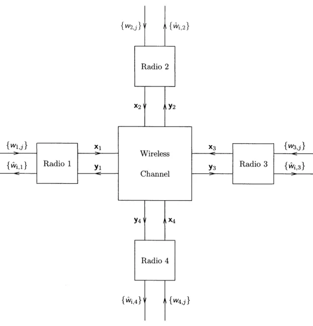
The general multi-terminal network model of [19] serves as the basis for our model, with the addition of wireless channel effects such as path-loss, fading, and interference. Consider a collection of M radio terminals seeking to communicate information-bearing signals w2,j,
e.g., voice, music, images, binary data. Each terminal transmits a signal, denoted by xi,
and receives a signal, denoted by yj. We leave the details of the structure of the transmit and receive signals to the specific instances of networks that we consider in later chapters. As we discuss in Section 2.3, many networks transmit digital representations of wij, thereby separating source and channel coding.
Fig. 2-1 depicts a block diagram for a wireless network with four terminals. It will be helpful to keep this general diagram in mind as we specialize it in later chapters.
W1,j XI {VAvi,1} Radio 1 Yi {w2,j} {Wvj,2} Radio 2 X2( A
aY2
Wireless Channel Y4 A X4 Radio 4 {Vi,4} {W4,j} X3 {W3,j Y3 Radio 3 {i, 3}RADIO
Network Protocols
USER/APP Signal Processing CHANNEL
{p vj} RF Circuitry
Figure 2-2: Radio block diagram.
Among many problem formulations for wireless communication, a fundamental one ad-dresses the limiting tradeoffs among resources, computational complexity, and transmission quality, e.g., end-to-end distortion, block error rates, and so forth. Just as important are questions of how to practically approach these fundamental tradeoffs. Problem formula-tions such as these can be made more specific by further developing the model. To this end, Section 2.1 describes radio hardware and its constraints. Section 2.2 describes the salient characteristics of wireless channels, including path-loss, fading, and interference. Fi-nally, Section 2.3 discusses how the general problem is often simplified by imposing layered
network architectures.
2.1
Radio Hardware and Constraints
In a general wireless setting, each terminal exchanges information with any of a number of other terminals in the system. Enabling such functionality requires a collection of radio de-vices that can each be viewed according to Fig. 2-2. Each radio consists of radio-frequency (RF) analog circuitry, and associated signal processing hardware and software, for emitting and observing information-bearing signals over the wireless channel, as well as distributed algorithms, or protocols, for coordinating the transmissions among the radios. In some systems, radios employ multi-antenna elements for increased capacity and improved ro-bustness.
Regulatory restrictions and practical limitations on radio implementation lead to several system constraints in our system model. Among other possibilities, for example, regulatory
bodies often place an average power constraint
lim
Z
xi[k]I < Pi, (2.1)k=1
on the transmitted signals. Furthermore, because of the near-far effect', it appears necessary to preclude radios from simultaneously transmitting and receiving on the same channel. This restriction constrains a radio so that
n
lim E xi [k]yi[k] = 0, (2.2)
k=1
where the orthogonality can be imposed via time- or frequency-division between transmis-sion and reception. Other constraints imposed by regulatory restrictions and implementa-tion limitaimplementa-tions include peak power and bandwidth constraints.
We note that we focus throughout the dissertation on algorithms that allow reductions in transmit power, often considered to be the dominant source of power consumption in wireless systems. Reductions in receiver power consumption can also improve terminal and network lifetime.
2.2
Wireless Channel Impairments
Our system model for wireless networks cannot be complete without capturing the salient effects of the wireless channels over which they operate. Indeed, many design decisions depend upon the particular channel conditions that prevail for a given application. In this section, we describe the significant channel distortions affecting wireless transmissions, and provide a fairly general mathematical description for use in our system models.
2.2.1 Multipath Propagation: Path-Loss and Fading
Wireless transmissions are severely degraded by the effects of so-called multipath
prop-agation. A signal emitted by a radio antenna propagates, e.g., in all directions
(omni-directionally) or, if the antenna is directed, only in a somewhat more restricted set of directions. Multipath arises because the propagated signal reflects off, refracts through,
'The near-far effect in this setting refers to a terminal's transmit signal drowning out the signals of other terminals at its receiver input because of path-loss and circuit isolation issues.
z [k] x, [k]
Saj, 1[1; k]
IF j [k]
xm [k 0 j, M[1k]:
Figure 2-3: Discrete-time, baseband-equivalent channel model for signal received by radio
3J.
and diffuses around scattering objects in the channel environment. Example obstructions include, e.g., buildings, trees, and cars in outdoor settings, and walls, furniture, and people in indoor settings. Scattering and propagation over longer distances increasingly attenuates signal power, an effect called path-loss. Thus, a radio receiver observes multiple attenuated and time-delayed versions of the transmitted signal, that are further corrupted by additive receiver thermal noise and other forms of interference. The copies of the transmitted signal might add constructively, thereby increasing the signal-to-noise ratio (SNR), or destruc-tively, thereby decreasing the SNR. With relative motion of the transmitters, receivers, and scatterers in the channel environment, SNR fluctuations occur across both time and fre-quency, and are generally called fading. We model the effects of path-loss and fading as a time-varying linear filter.
Although radio transmissions are often continuous-time signals centered at carrier fre-quencies ranging from kHz to GHz, i.e., passband signals, when the signals are bandlim-ited, it is often conceptually convenient to model them as discrete-time signals centered at 0 Hz, i.e., baseband signals. Similarly, we model the continuous-time, passband channel effects with an associated discrete-time, baseband channel. Baseband-equivalent models are convenient because they suppress the issues of frequency up- and down-conversion, and discrete-time models are appealing because architectures designed for them can be efficiently implemented in digital signal processing (DSP) hardware.
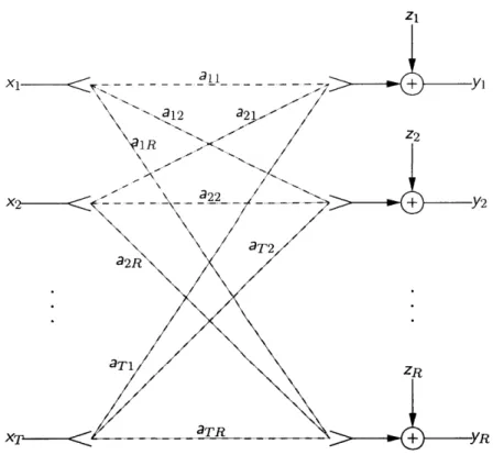
Fig. 2-3 shows a fairly general, discrete-time, baseband-equivalent channel model for each of the received signals in a wireless network consisting of M terminals. For a given contiguous transmission bandwidth W, we use a baseband-equivalent, discrete-time channel model with W (complex) channel uses per second. Transmitter i emits signal xi[k], and
Time Selective Time Nonselective Frequency Selective aj,i[l; k] aj,i [l; 0] 6[k]
Frequency Nonselective aji[0; k] 6[l] aji [0; 0] 3[l]
3[k]
Table 2.1: Form of aji[l; k] for a several important channel conditions.
receiver
j
observes signal yi[k]. The effects of multipath propagation on x [k] are modeled as convolution with the time-varying, discrete-time, linear filter a,i [1; k], so that the received signals are modeled by the relationshipM
yj [k] = aj,i [1; k] xi [k - 1] + zj [k], j = 1, 2, 1 M. (2.3)
i=1 I
Here zj[k] captures the effects of receiver thermal noise and other forms of interference. Multipath propagation manifests itself in a variety of ways depending upon the form of aj,i[l; k]. For example, if aj,i[l; k] = aj,i[A; k] J[l - A]-a single, time-varying tap with delay A--the channel experienced by signal xi[k] in transmission to radio
j
is called time selective and frequency nonselective. Table 2.1 characterizes the form of aj,i[l; k] for several other important classes of wireless channels. The prevailing kind of channel can result from system constraints, e.g., bandwidth limitations of regulatory bodies such as the FCC, or design choices, e.g., allowing users to be mobile at varying speeds, or employingspread-spectrum signals [42, 60, 61].
Statistical Characterization
Because the scattering environment is often too complex for precise physical modeling to be tractable, system designers frequently employ statistical models for characterizing the chan-nel effects. Such models are developed based upon the physics of radio-wave propagation and augmented with data obtained from measurements of real-world channels [42, 61].
Under the well-known Rayleigh fading model, the fading coefficients aj,i[l; k] are mod-eled as zero-mean, stationary complex jointly Gaussian random sequences in k that are independent for different values of i and
j
(with radio separations greater than roughly half the carrier wavelength, about 30 cm for a carrier frequency of 1 GHz) and sometimes independent for different values of 1 (called the uncorrelated scattering model). Temporalcorrelation models have also been developed, e.g., the Jakes model [61, 42].
We assign path-loss between radios i and
j
using models based upon the network ge-ometry. For example, field measurements suggest path-loss models proportional to G/d'j, where dij is the distance between radio i and radioj,
G captures the effects of antenna gain and carrier wavelength, and v is a constant whose measured value typically lies in the range 3 < v < 5 [61].Channel State Information
An important issue affecting the design and analysis of transmissions protocols is channel state information, i.e., how much radios know about each channel realization throughout the network. For example, using training signals, e.g., pilot tones or symbols, the receivers may estimate the multipath coefficients affecting their respective received signals. Such channel measurement and estimation is reasonable when the channels are not over param-eterized, e.g., systems with small numbers of users transmitting at the same time in the same bandwidth within a given local area, channels exhibiting only a few significant non-zero taps, and slow enough temporal variations that allow estimation to provide accurate estimates.
Once channel state information is acquired at the distributed radio receivers, protocol designs can feed this information back to the transmitters. Feedback allows the transmitters to adapt their transmissions to the realized channel in effect, often leading to performance improvements when accurate channel state information is obtainable.
2.2.2 Interference and Other Issues
In addition to the salient channel effects such as path-loss and fading, and radio model variants such as multiple antennas at the transmitters and receivers, general wireless systems exhibit instances of many simpler channel models, including: multiple-access, i.e., several transmitters conveying information to a common receiver; broadcast, i.e., one transmitter convening information to several separate receivers; interference, i.e., several transmitters conveying information to several separate receivers; and two-way, i.e., two radios conveying information two one another. Each of these simpler examples exhibit different types of
interference among multiple transmitted and/or received signals, and all of these types of
Furthermore, any of these simpler models can incorporate feedback, i.e., (partial) knowl-edge of the received signals at the transmitter, and relaying, i.e., terminals without infor-mation to transmit or receive assist other transmitting and receiving terminals. These possibilities correspond to different ways for the terminals to interact. In addition to these interference and structural variations, networks might incorporate source-channel interac-tions that introduce additional possibilities. One such example is voice-activity detection in the IS-95 system [611. Indeed, general wireless networks represent a huge space for designing and optimizing systems for various applications.
2.3
Network Architectures
Many different wireless network architectures have appeared in practice due to the broad array of applications and the varying extent to which providers desire to leverage existing infrastructure. For example, wireless network architectures for delivering voice or data and multimedia services tend to be quite different.
Often, these complicated systems are simplified along several dimensions to make the resulting problem formulations hierarchical and generally more tractable. For example, in a cellular setting, the coverage area is divided into "cells", each with its own basestation and a given amount of channel bandwidth. If the cell bandwidth is less than the total system bandwidth, then the system employs frequency-reuse to limit interference between cells. Within a cell, the bandwidth is often divided between a multiple-access uplink (mobiles to basestation) and broadcast downlink (basestation to mobiles). Finally, even the uplink and downlink channels are further divided into essentially orthogonal point-to-point channels to reduce receiver complexity. Feedback is somewhat limited, and relaying has not been em-ployed in these systems to date. We call a set of restrictions on the structure of the network an architecture; thus, we have described a standard cellular architecture for delivering voice traffic.
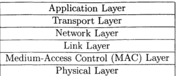
Although design and implementation of wireless networks, and communication networks in general, can be approached in a variety of ways, many architectures are partitioned into a set of protocol layers [10, 61] as shown in Fig. 1-2. We include Fig. 1-2 here in abbreviated form as Fig. 2-4 for convenience. These layers range from the highest-layer (farthest from the wireless channel, most abstracted), the application layer, to the lowest layer (closest
Application Layer Transport Layer
Network Layer Link Layer
Medium-Access Control (MAC) Layer Physical Layer
Figure 2-4: Protocol stack for a general layered network architecture.
to the wireless channel, least abstracted), the physical layer. Roughly speaking, the tasks allocated to each layer are as follows. The application layer generates or handles user signals {wi,j}, and conveys them through an interface to the transport layer. The transport
layer often performs packet sequencing, end-to-end retransmission, and flow control. The network layer routes messages through the network over a set of point-to-point links created
by the link layer. The link layer, and its associated medium-access control (MAC)
sub-layer, maintains a set of virtual point-to-point communication links built on top of the
physical layer. Finally, the physical layer incorporates a majority of the analog circuitry and signal processing described in Section 2.1 and provides for transmission of signals {xi} and reception and processing of signals {yj} over the wireless channel.
The layered approach is convenient because it allows for abstraction barriers in the system. In particular, it allows for the design of general networks, from the network layer down, that support a variety of applications. The simplest example of this type is the separation of source and channel coding on a point-to-point link, where the interface between the two subsystems is bits. Furthermore, standardized layered architectures allow different manufacturers to provide components for different layers or complete radio implementations that inter-operate.
2.3.1 Prevalent Wireless Network Architectures
It will be convenient throughout the dissertation to classify network architectures into two broad classes called infrastructure and ad-hoc networks, respectively. Each of these has gone by different names in the past, but we borrow our terminology from current wireless local area network (LAN) standards [35] that allow for both configurations. We now describe these two classes of architectures.
Infrastructure Networks
In an infrastructure network, low-power, possibly mobile radio terminals connect via local, high-power, usually stationary radios, called access points, that are themselves connected via a backbone network. Typically, the backbone network is an existing wire-line network, such as the public switch telephone network or the Internet. Examples of such infrastructure networks include: current cellular networks, in which the basestations act as access points, for voice and data services; satellite networks, in which case the satellites act as access points, also for voice and data services, and certain wireless LANs, from which we have borrowed the term "access point". Two distinctive features of infrastructure networks are the power and processing asymmetries between radio terminals and access points, and the fact that all communication occurs through at least one access point. Even closely located radio terminals do not communicate directly, but instead communicate through their local access point.
Nominally, the architecture of an infrastructure network is organized as follows. The network layer assigns mobile radios to access points, using some information about channel conditions. Once a mobile is assigned to an access point, all communication occurs with that access point; thus, routing is not important within a cell. Sometimes, mobility requires handoff between access points, and this function is also handled by the network layer. This assignment of mobiles to access points creates a collection of "cells"; hence the name "cellu-lar". The medium access control sub-layer at each access point allocates available channel bandwidth to mobiles assigned to it. Frequency reuse among the cells and orthogonal uplink (mobile to basestation) and downlink (basestation to mobile) transmissions limit interfer-ence. The physical layer codes and modulates for point-to-point transmission to and from the access point. Intra- and inter-cell interference is typically treated as noise, although multi-user detection can be employed to combat intra-cell interference.
Ad-Hoc Networks
In an ad-hoc (or packet radio, or peer-to-peer) network, radio terminals generally have more symmetric power and processing capabilities, and they do not leverage access points or a backbone network, as in infrastructure networks. Examples of ad-hoc networks include CB and amateur radio, emerging wireless LANs, and wireless sensor networks. In principle, the
distinctive features of ad-hoc networks include their potentially fast and ad-hoc deployment as well as their resulting robustness to loss of radio terminals. For these reasons, ad-hoc networks initially found application primarily in military settings, but are more recently penetrating certain commercial arenas such as home networking.
The layered architecture of ad-hoc networks is based largely upon wire-line store-and-forward networks. Terminals communicate primarily with nearby terminals, and exchange neighbor information to enable routing throughout the network. In contrast to infrastruc-ture networks that employ direct wireless transmission between mobiles and a basestation, ad-hoc networks have gravitated toward cascade transmission-often called multihop routing in the ad-hoc networking literature-between source and destination terminals via several intermediate terminals. Cascade transmission potentially conserves energy by combating path-loss and limiting interference in the network.
Another architectural device frequently considered for ad-hoc networks is clustering. Clustering arises in a variety of forms in large, dense ad-hoc networks. (See [15, 37] and the references therein.) In essence, a clustering algorithm partitions a large ad-hoc network into a set of clusters, each centered around a clusterhead. Terminals communicate directly to their associated clusterhead, and routing is usually performed between clusterheads. In this sense, clustering mimics some of the features of infrastructure networks: clusters cor-respond to cells and clusterheads corcor-respond to access points. However, in ad-hoc settings the clusters and clusterheads may be varying as the network operates, the clusterheads themselves can have information to transmit, and the clusterhead network must share the wireless bandwidth.
2.3.2 New Architectures Incorporating Cooperation
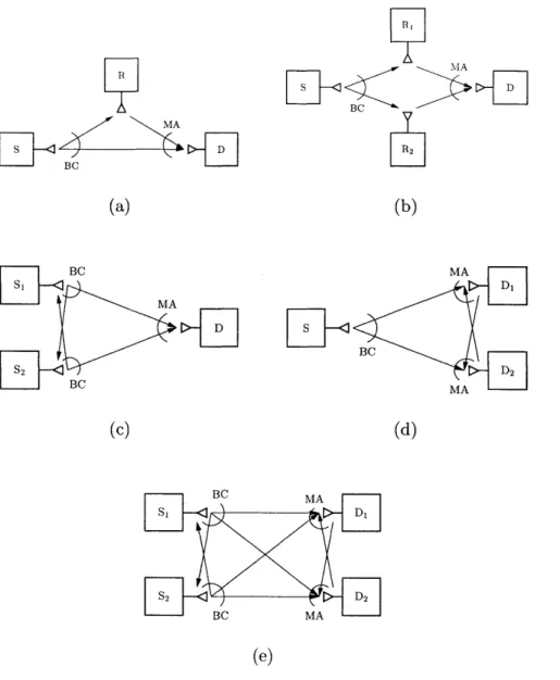
Many options arise for cooperative diversity in wireless settings. Fig. 2-5 depicts block diagrams for a number of these options. The configurations in Fig. 2-5 specialize to well known channel models when cooperation is not employed. For example, as we discuss in Section 3.4, the classical relay channel in Fig. 2-5(a) specializes to direct transmission when the relay is removed, and cascade transmission when the destination cannot receive (or ignores) the source transmission. The configurations in Fig. 2-5(c)-(e) specialize to the classical multiple-access channel, broadcast channel, and interference channel, respectively. Of these configurations, we focus throughout the dissertation on the multiple-access and
Y
BC (a) BC MA BC (c) <BC -E (b) MA BC MA(d)
BC MA BC MA (e)Figure 2-5: Various relaying configurations that arise in wireless networks: (a) classical relay channel, (b) parallel relay channel, (c) multiple-access channel with relaying, (d) broadcast channel with relaying, (e) interference channel with relaying.
interference channel versions of Fig. 2-5(c) and Fig. 2-5(e), respectively. We include the other possibilities for completeness as well as to encourage their study.
Chapter 3
Background and Related Literature
This chapter summarizes important references from a broad array of literature that relate to the problems studied by the dissertation. Our objective is to make the reader aware of the many considerations involved, highlight the particular scenarios that we study throughout the dissertation, and encourage further work in the area. Because cooperative diversity is a network problem, it can be viewed as living across several of the layers in a layered network architecture as discussed in Section 2.3. While the ideas build significantly from work on the relay channel within the information theory community, there are several other bodies of research to build from and relate to, including single-user multi-antenna systems and various results for ad-hoc networks, specifically in multihop routing.
Section 3.1 begins by summarizing work on the classical relay channel, the simplest cooperative example in Fig. 2-5. Evaluating the utility of cooperation in wireless systems starts with considering the issue of fading. Section 3.2 summarizes relevant notions of channel capacity in fading environments. It then seems natural to compare performance of cooperative transmission and reception protocols for creating virtual arrays to the perfor-mance of physical antenna arrays. Section 3.3 surveys important results from the physical array literature. Finally, Section 3.4 cites several interesting results that have studied wire-less networks with an eye toward breaking barriers within the standard layered network architectures in order to improve performance.
In principle, fundamental performance limits for general wireless systems can be de-veloped. Most generally, results would indicate the limiting tradeoffs between achievable channel rates and distortions on the information-bearing signals, without regard to
com-putational complexity. However, surprisingly many of even the simplest network channel models have not been yet fully characterized. For example, the capacity for general relay channels, broadcast channels, and interference channels remain unknown [19]. Since a gen-eral wireless system gengen-eralizes these models, as well as all the models shown Fig. 2-5, there is much work to be done.
3.1
Relay Channels and Extensions
Relay channels and their multi-terminal extensions are central to our study of cooperative diversity. Much of the work on these channel models to date has focused on discrete or ad-ditive white Gaussian noise channels, and examined performance in terms of the well-known Shannon capacity (or capacity region) [19]. Only the more recent work has considered the issue of multipath fading, which is another central issue of this dissertation. We also focus on the multi-terminal aspects of relaying or cooperative diversity problems, in particular,
the multiple-access channel case and, to some extent, the interference channel case.
The classical relay channel models a class of three terminal communication channels (cf. Fig. 2-5(a)), originally introduced and examined by van der Meulen [84, 85], and subse-quently studied by a number of authors, primarily from the information theory community. The distinctive property of relay channels in general is that certain terminals, called "re-lays", receive, process, and re-transmit some information bearing signal(s) of interest in order to improve performance of the system. As we illustrated in Fig. 2-5, in some cases extra terminals in the network, without information to transmit or receive, serve as relays, while in other cases transmitting and/or receiving terminals can cooperate by serving as
relays for one another.
Cover and El Gamal [17] examine certain non-faded relay channels, developing lower and upper bounds on the channel capacity via random coding and converse arguments, respectively. Generally these lower and upper bounds do not coincide, except in the class of
degraded relay channels [17]. While the class of degraded relay channels is mathematically
convenient, we stress that none of the wireless channels found in practice fall into this class. The lower bounds on capacity, i.e., achievable rates, are obtained via three structurally different random coding schemes, referred to in [17] as facilitation, cooperation, and
obser-vation, respectively.'. The facilitation scheme is nothing special: the relay does not actively
help the source, but rather, facilitates the source transmission by inducing as little interfer-ence as possible. The cooperation and observation schemes are more involved, as we now describe.
In the cooperation scheme of [17], the relay fully decodes the source message, and re-transmits some information about that signal to the destination. More precisely, the relay encodes the bin index of the previous source message, from a random binning of the source messages as in well-known Slepian-Wolf coding [19]. The source transmits the superposition of a new encoded message and the encoded bin index of the previous message, in a block-Markov fashion. The destination suitably combines the source and relay transmissions, possibly coherently combining the identical bin index transmissions, in order to achieve higher rates than with the direct transmission alone. We note that practical implementa-tions of this cooperation scheme can be obtained with suitable configuraimplementa-tions of multi-level codes [87].
Of course, full decoding at the relay can, in some circumstances, be a limiting factor; the rates achieved using this form of cooperation are no greater than the capacity of direct transmission from the source to the relay. As one alternative in such circumstances, Cover and El Gamal propose the observation scheme, in which the relay encodes a quantized version of its received signal. The destination combines information about the relay received signal with its own in order to form a better estimate of the source message. For Gaussian noise channels, the destination can essentially average to two observations of the source message, thereby reducing the noise.
Broadly speaking, we can expect cooperation (resp. observation) to be most beneficial when the channel between the source and relay (resp. relay and destination) is particularly good. For intermediate regimes, Cover and El Gamal propose superposition of the two schemes in order to maximize the achievable rates.
Of the remaining configurations depicted in Fig. 2-5, only parallel relay channels (cf. Fig. 2-5(b)) and multiple-access channels with relaying (cf. Fig. 2-5(c)) have received at-tention in the literature. Schein and Gallager [66] introduced the parallel relay channel model in an attempt to make the classical relay channel symmetric. Schein [65] considers a
'The names facilitation and cooperation were introduced in [171, but the authors did not give a name to their third approach. We use the name observation throughout the dissertation for convenience


![Table 2.1: Form of aji[l; k] for a several important channel conditions.](https://thumb-eu.123doks.com/thumbv2/123doknet/14489838.525692/32.918.240.704.118.189/table-form-aji-l-k-important-channel-conditions.webp)