Design, Optimization, and Applications of
Few-Cycle Ti:Sapphire Lasers
by Li-Jin Chen
B.S., Electrical Engineering, National Taiwan University, 2003 M.S., Electro-Optical Engineering, National Taiwan University, 2005 Submitted to the Department of Electrical Engineering and Computer Science
in partial fulfillment of the requirements for the degree of Doctor of Philosophy in Electrical Engineering
at the
MASSACHUSETTS INSTITUTE OF TECHNOLOGY February 2012
ARCHNVES
ASSACHUSETTS INST E OF TECHNOLOGYLAR
2
R
012
LIBRARIES
@ Massachusetts Institute of Technology 2012. All right reserved.A uthor... ... . . . ....
Department of Electrical Engineering and Computer Science December 2,2011
Certified by...
Accepted by...
Chai
Franz X. KArtner Professor of Electrical Engineering Thesis Supervisor
-Le e Kolodziejski
Professor of Electrica Engineering rman, Department Committee on Graduate Theses
Design, Optimization, and Applications of
Few-Cycle Ti:Sapphire Lasers
by
Li-Jin Chen
Submitted to the Department of Electrical Engineering and Computer Science on December 1, 2012,
in partial fulfillment of the requirements for the degree of Doctor of Philosophy in Electrical Engineering and Computer Science
Abstract
Ti:Sapphire mode-locked lasers are a unique technology that enables a wide variety of applications. Owing to the ultrabroadband nature of the Ti:sapphire crystal and the invention of precisely engineered dispersion-compensating mirrors (DCMs), these lasers are now capable of generating stable pulse trains directly with octave-spanning spectrum, few-cycle pulse duration, and a desired repetition rate from a compact system. This paves the way to a new world of emerging applications ranging from the search of exoplanets, high-harmonic generation, to precision measurement
Qualitatively, the key to the stable mode-locking of Ti:Sapphire lasers lies in the balance of various spatial and temporal nonlinear effects such as self-amplitude modulation(SAM), self-phase modulation(SPM), saturable absorption, self-focusing, gain-filtering, gain-guiding, and so on. However, since much shorter pulses and much higher intracavity intensities are often reached inside the laser gain medium, the spatiotemporal dynamics in such lasers are even more complicated as non-negligible multi-photon processes also come into play. Due to the strong coupling between these effects, performing a reliable analysis and optimization become extremely challenging.
In this thesis we study the spatiotemporal dynamics of pulse evolution in the few-cycle regime and provide guidelines for designing and optimizing these lasers for repetition rate ranging from 85 MHz to 2 GHz. The essential background reviews as well as key concepts in KLM lasers will be given together with a demonstration of octave-spanning Ti:sapphire lasers with record-high repetition rate. A numerical model for simulating the full spatiotemporal dynamics is introduced. For an efficient numerical calculation, GPU accelerated computing techniques are adopted. With this model, many unique features that are observed from the experiments can be simulated for the first time. A novel type of output coupler called gain-matched output coupler is introduced which can greatly reduce the nonlinearity required for ultra-broadband mode-locking. Already at pump power levels close to the cw lasing threshold it is possible to initiate robust mode-locking and generate <8 fs output pulses from Ti:sapphire lasers with excellent beam quality operating in the center of its stability range. Moreover, the development of visible astro-combs based on few-cycle Ti:sapphire lasers will be discussed. This application is enabled by two promising technologies (broadband zero-GDD mirror sets and Cherenkov radiation in the few-cycle regime) which are developed to increase the repetition rate and
spectral coverage of the laser systems operated in the few-cycle regime. Fiber-optic Cherenkov radiation in the few-cycle regime excited by sub-10fs Ti:sapphire pulses is studied. Through a dispersion-engineered PCF driven by a few-cycle pulse, the nonlinearity can produce highly efficient broadband frequency up-conversion to the visible wavelength range. Finally, we propose and demonstrate a new approach for broadband dispersion-free optical cavities using a zero-GDD mirror set; With the first zero-GDD mirror pair, the construction of a -40 GHz filtering cavity with 100 nm bandwidth for a green astro-comb (480-580 nm) was demonstrated. Finally, the thesis is concluded by discussing the practical issues related to the construction of a easy-to-operate, long-term stable few-cycle Ti:sapphire laser.
Thesis Supervisor: Franz X. K~irtner
Acknowledgements
First of all, I would like to thank my advisor Prof. Franz Kartner for the guidance and support during my PhD life. He is a great mentor, friend, and research supervisor. He not only gives me a lot of freedom in research but also loves to share his deep physical insight as well as life experience with us, which makes my entire PhD life joyful. I also would like to thank Prof. Erich Ippen and Prof. Leslie Kolodziejski who continuously give me valuable comments over the past few years since the OAWG project (the first research project I was working on at MIT) to my thesis defense.
Working at MIT is nothing but a great fun. As an international student who has to travel to the other end of the Earth and start a whole new life in a foreign country, I feel so lucky to have the company of all OQE group members for these years. Everyone is always friendly and helpful whenever I was bothered by any problem in my research or daily life. I especially thank Dr. Andrew Benedick for leading me into the field of few-cycle Ti:sapphire lasers. It is my great pleasure to work with such a creative and diligent man who always takes a positive attitude when facing challenges. I thank Dr. Jonathan Birge for passing his precious knowledge in coating design to me. I thank Dr. Guoqing Chang for being such a wonderful colleague and friend for these years. I enjoy having all kinds of discussion with Dr. Chang that simply makes my time in lab really enjoyable. I also thank the astro-comb team at Harvard University for giving me the opportunity to participate one of the coolest projects that the astronomers are working on. I also want to thank all members in Republic of China (Taiwan) student association and
especially those in our OQE group (Tsung-Han Tsai, Chien-Jen Lai, Hsiang-Chieh Lee, Hung-Wen Chen, Shu-Wei Huang, and Jonathan Liu). Even if I am standing on the other end of the Earth, this place feels like home to me with their company. I wish them best luck for their future research and life.
Finally and most importantly, I wish to express my highest personal gratitude to my wife Huei-Yuan Hsiao, my parents Chen-Chin Chen and Yen-Fong Kao, and my elder brother Jia-Fu Chen. They always give me the greatest support for everything I want to do and ask for no return. Without their love and care, I could not finish my PhD and this thesis. This thesis is dedicated to them.
Curriculum Vitae
Education
MIT, Ph.D. in Electrical Engineering and Computer Science, Feb 2012 National Taiwan University, M.S. in Electro-Optical Engineering, June 2005 National Taiwan University, B.S. in Electrical Engineering, June 2003 Patents
1. C.-K. Sun, L.-I. Chen. H.-W. Chen, "Plastic Waveguide for Terahertz Wave," US Patent 7,409,132.
2. F. X. Ksrtner, L.-I. Chen, "Mode-locking with reduced nonlinearity using gain-matching output couplers", MIT Case NO. 14156; US patent pending.
3. F. X. Ksrtner, L.-I. Chen. G. Q. Chang "Broadband Dispersion-Free Optical Filter Cavities Based on Dielectric Mirrors with Complementary Dispersion", MIT Case NO. 14229; US patent pending.
Refereed Journal Publications
1. L.I Chen. C.-J. Lai, and F. X. Kirtner, "Spatiotemporal model for few-cycle
Ti:sapphire lasers," Manuscript in preparation.
2. S.-W. Huang, G. Cirmi, J. Moses, K.-H. Hong, S. Bhardwaj, J. R. Birge, L.-. Chen
E. Li, B. Eggleton, G. Cerullo, and F. X. Ksrtner, "Scalable High-Energy
Sub-Cycle Waveform Synthesis for Strong-Field Physics," Nature Photonics 5, 475-479,2011.
3. G. Q. Chang, L.-I. Chen. and F. X. Kartner, "Fiber-Optic Cherenkov radiation in
the Few-Cycle Regime," Opt Express 19, 6635-6647,2011.
4. L.-. Chen G. Q. Chang, J. R. Birge, and F. X. Kartner, "High-Finesse
Dispersion-Free Cavities for Broadband Filtration of Laser Comb Lines," Opt Express 18, 23204-23211,2010.
5. L.-I. Chen. M. Y. Sander, F. X. Ksrtner, "Kerr-lens Mode-locking with
Minimum Nonlinearity Using Gain-Matching Output Couplers", Opt Lett 35,
2916-2918,2010.
6. G. Q. Chang, L-1. Chen, and F. X. Kirtner, "Highly Efficient Cherenkov Radiation in Photonic Crystal Fibers for Broadband Visible Wavelength Generation," Opt Lett 35(14), 2361-2363, 2010.
7. H.-W. Chen, T. Sosnowski, C.-H. Liu, L.-L. Chen.
J.
Birge, A Galvanauskas, F. X.Ksrtner, and G. Q. Chang, "Chirally-coupled-core Yb-fiber laser delivering 80-fs pulses with diffraction-limited beam quality warranted by a high-dispersion-mirror based compressor," Opt Express 18, 24699, 2010.
8. C.-H. Li, A Glenday, A Benedick, G. Q. Chang, L.-L. Chen, C. Cramer, P. Fendel,
G. Furesz, F. X. Ksrtner, S. Korzennik, D. F. Phillips, D. Sasselov, A
Szentgyorgyi, R. L Walsworth, "In-situ determination of astro-comb
calibration lines to better than 10 cm/s," Opt Express 18, 13239-13249, 2010.
9. A J. Benedick, G. Q. Chang, J. R. Birge, L.- Chen. A Glenday, C. H. Li, D. F.
Phillips, A Szentgyorgyi, S. Korzennik, G. Furesz, R. L Walsworth, and F. X. Ksrtner, "Visible wavelength astro-comb," Opt Express 18, 19175-19184, 2010.
10. E. L. Falcso-Filho, C.-J. Lai, K.-H. Hong, V.-M. Gkortsas, S.-W. Huang, L-. Chen
and Franz X. Kurtner, "Scaling of high-order harmonic efficiencies with visible wavelength drivers: a route to efficient EUV sources," Appl. Phys. Lett.
97, 061107,2010
11. L.-L. Chen. A. J. Benedick, J. R. Birge, M. Y. Sander, and F. X. Kurtner, "Octave-spanning, dual-output 2.166 GHz Ti:sapphire laser," Opt Express 16,
20699-20705,2008.
12. H.-W. Chen, Y.-T. Li, J.-L. Kuo, J.-Y. Lu, L.-. Chen C.-L. Pan, and C.-K. Sun, "Investigation on Spectral Loss Characteristics of Subwavelength THz Fibers," Opt Lett 32(9), 1017-1019, 2007.
13. L.-J. Chen H.-W. Chen, T.-F. Kao, J.-Y. Lu, and C.-K. Sun, "Low-loss
Subwavelength Plastic Fiber for Terahertz Waveguiding," Opt Lett. 31(3),
308-310, 2006.
14. L.-. Chen T.-F. Kao, J.-Y. Lu, and C.-K Sun, "A Simple Terahertz Spectrometer Based on a Low-Reflectivity Fabry-Perot Interferometer Using Fourier Transform Spectroscopy," Opt Express 14,3840-3846,2006.
15. J.-Y. Lu, L.-. Chen. C.-K. Sun and et. al., "Terahertz microchip for illicit drug detection," IEEE Photon. Technol. Lett. 18(21), 2254-2256,2006.
16. T.-F. Kao, H.-H. Chang, L.-. Chen J.-Y. Lu, A.-S. Liu, Y.-C. Yu, R.-B. Wu, W.-S. Liu, J.-I. Chyi, and C.-K Sun, "Frequency Tunability of Terahertz Photonic
Transmitters," Appl. Phys. Lett 88, 093501,2006.
17. J.-Y. Lu, H.-H. Chang, L-L. Chen. M.-C. Tien, and C.-K. Sun,
"Optoelectronic-Based High-Efficiency Quasi-CW Terahertz Imaging," IEEE Photon. Technol. Lett. 17(11), 2406-2408,2005.
18. M.-C. Tien, H.-H. Chang, J.-Y. Lu, L-. Chen. S.-Y. Chen, R.-B. Wu, W.-S. Liu, J.-I.
Chyi, and C.-K. Sun, "Device Saturation Behavior of Submillimeter-wave Membrane Photonic Transmitters," IEEE Photon. Technol. Lett. 16(3), 873-875,2004.
19. S.-P. Tai, M.-C. Chan, T.-H. Tsai, S.-H. Guol, L.-J. Chen. and C.-K Sun,
"Two-photon Fluorescence Microscope with a Hollow-core Photonic Crystal Fiber," Opt Express 12(25), 6122-6128, 2004.
Refereed Conference Proceedings (*) Invited
1. (*) L.-L Chen. G. Q. Chang, and F. X. Kartner, "Highly efficient, broadband Cherenkov radiation in photonic crystal fibers," paper CTuT3, CLEO/QELS, San Jose, CA, USA, 2010.
2. L.-. Chen. C.-J. Lai, and F. X. Kartner, "The Role of Plasma Formation in Mode-locking of Few-cycle Ti:sapphire Lasers: A Spatiotemporal Model," paper
CWR5, CLEO: Science & Innovations, Baltimore, 2011.
3. L.-L. Chen, C.-J. Lai, and F. X Ksrtner, "Spatiotemporal Model of Passively Mode-locked Few-cycle Ti:sapphire Lasers: The Role of Plasma Formation," paper HThC3, High-Intensity Lasers and High-Field Phenomena (HILAS),
Istanbul, Turkey, 2011
4. L.-. Chen. G. Q. Chang, C.-H. Li, A G. Glenday, A J. Benedick, D. F. Phillips, R. L. Walsworth, and F. X Kartner, "High-finesse dispersion-free cavities for broadband filtration of laser comb lines," paper TuF1, 17th international conference on Ultrafast Phenomena, Snowmass village, CO, USA; Ultrafast
5. L.-f. Chen, M. Y. Sander, and F. X Kartner, "Mode-locking with minimum nonlinearity using inverse-gain output couplers," paper CTh17, CLEO/QELS, San Jose, 2010
6. L.-I. Chen G. Q. Chang, J. R. Birge, and F. X. Kartner, "Complementary chirped-mirror pair for broadband dispersion-free cavities," paper FB5, Optical
Interference Coatings, Tucson, AZ, USA, 2010.
7. L.-L. Chen A J. Benedick, J. R. Birge, M. Y. Sander, F. X. Kartner, "2GHz
octave-spanning Ti:sapphire Laser with non-intrusive carrier-envelope phase stabilization", paper WZ1, IEEE Lasers and Electro-Optics Society (LEOS), Newport Beach, CA, USA, 2008.
8. L.-. Chen. H.-W. Chen, T.-F. Kao, J.-Y. Lu, and C.-K. Sun, "Low-loss
Subwavelength THz Plastic Fibers," paper CMS1, CLEO/QELS, Long Beach,
CA, USA, 2006.
9. L.-L. Chen. T.-F. Kao, H.-H. Chang, J.-Y. Lu, and C.-K. Sun, 'Terahertz Fourier
Transform Spectrometer Based on a Low-Reflectivity Fabry-Perot Interferometer," paper QTu12, CLEO/QELS, Baltimore, MD, USA, 2005.
10. (*) M. Y. Sander, L.-L Chen and F. X Kartner, "Spatial and Temporal Modeling
of Few-Cycle Ti:Sapphire Lasers", URSI GASS 2011, Istanbul, Turkey.
11. (*) G. Q. Chang, L-L Chen and F. X Kirtner, "Fiber-optic Cherenkov radiation
excited by few-cycle pulses," paper 7937-57, SPIE Photonics West, San Francisco, CA, USA 2011.
12. (*) Chi-Kunag Sun, L.-I. Chen, H.-W. Chen, and J.-Y. Lu, "Subwavelength Plastic Fiber for Terahertz Wave Guiding," Optics East/ Conference on Terahertz Physics, Devices, and Systems, Boston, MA, paper 6373-12; Proceedings of SPIE 6373, 63730F, 2006.
13. (*) J.-Y. Lu, H.-W. Chen, L-L Chen. and C.-K. Sun, "Sub-Wavelength THz Plastic
Fibers," in Proceeding of Terahertz and Gigahertz Electronics and Photonics VI, Photonics West, paper 6472-7, San Jose, CA, USA; Proceedings of SPIE
6472,647208, 2007.
14. (*) E. P. Ippen, A J. Benedick, J. R. Birge, H. Byun, L.f Chen. G. Q. Chang, D. Chao, J. Morse, A Motamedi, M. Sander, G. Petrich, L Kolodziejski, and F. Ksrtner, "Optical arbitrary waveform generation," paper JThC4, CLEO/QELS, San Jose, 2010
15. (*) C.-H. Li, A J. Benedick, C. E. Cramer, G. Q. Chang, L.- Chen. P. Fendel, G. Furesz, A G. Glenday, F. X Ksrtner, D. F. Phillips, D. Sasselov, A Szentgyorgy, R. L Walsworth, "Laser frequency combs for precision astrophysical spectroscopy," paper EG4.3, CLEO Europe/EQEC, Munich, Germany, 2009.
16. (*) C.-H. Li, A J. Benedick, C. E. Cramer, G. Q. Chang, L.-L Chen. P. Fendel, G. Furesz, A G. Glenday, F. X Kartner, D. F. Phillips, D. Sasselov, A Szentgyorgyi, and R. L. Walsworth, "Femtosecond Laser Frequency Comb for Precision Astrophysical Spectroscopy," paper CMII1, CLEO/QELS, San Jose, CA, USA,
2009.
17. G. Q. Chang, L.-. Chen. and F. X Kirtner, "Fiber-Optic Cherenkov radiation in
the Few-Cycle Regime", paper CWR2, CLEO: Science & Innovations, Baltimore, 2011.
18. J.-Y. Lu, L.-. Chen. T.-F. Kao, H.-H. Chang, C.-K. Sun, A-S. Liu, Y.-C. Yu, R.-B. Wu,
W.-S. Liu, and J.-I. Chyi, 'Terahertz Biochip for Illicit Drug Detection," paper
19. J.-Y. Lu, L.-I. Chen T.-F. Kao, H.-H. Chang, A.-S. Liu, Y.-C. Yu, R.-B. Wu, W.-S. Liu, J.-I. Chyi, C.-L. Pan, M.-C. Tsai, and C.-K. Sun, "THz Biochip Based on
Optoelectronic Devices," Optics East/Sensors and Photonics for Applications in Industry, Life Sciences, and Communications, Boston, MA, USA, Optoelectronic Devices: Physics, Fabrication, and Application II, paper
6013-19; Proceedings of SPIE 6013, pp. 601301-1 - 601301-8, 2005.
20. T.-F. Kao, L.-J. Chen H.-H. Chang, J.-Y. Lu, A-S. Liu, Y.-C. Yu, R.-B. Wu, W.-S. Liu,
J.-l. Chyi, and C.-K Sun, "Broadband-response and Frequency-tunable
Terahertz Photonic Transmitters with High Efficiency," paper CTuBB6,
CLEO/QELS, Baltimore, MD, USA, 2005.
21. C.-H. Li, G. Q. Chang, L.-I. Chen. D. F. Philips, F. X. Ksrtner, R. L. Walsworth "Lab Demonstration and Characterization of a Green Astro-comb" paper
AME5, Advanced Solid-State Photonics (ASSP), Istanbul, Turkey, 2011.
22. H.-W. Chen, J.-Y. Lu, L.-. Chen. Po-Jui Chiang, Hung-Chun Chang, Yu-Tai Lu, Ci-Ling Pan, and C.-K Sun, "THz Directional Fiber Coupler," paper CThLL7,
CLEO/QELS, Baltimore, MD, USA, 2007.
23. H.-W. Chen, J.-Y. Lu, L.-. Chen Y.-T. Lu, C.-L. Pan, and C.-K Sun, "Spectral Loss
Characteristics of Subwavelength THz Fibers," paper CJWA107, CLEO/QELS, Baltimore, MD, USA, 2007.
24. J.-Y. Lu, H.-H. Chang, L.-L Chen M.-C. Tien, and C.-K. Sun, 'Terahertz-Wave Molecular Imaging Based on a Compact High-Efficiency Photonic Transmitter," The 3rd Annual Meeting of the Society for Molecular Imaging,
St Louis, MO, USA, 2004.
25. J.-Y. Lu, H.-H. Chang, L-L Chen, M.-C. Tien, and C.-K Sun, "Quasi-CW THz-Imaging Based on a High-Efficiency Tunable Photonic Transmitter," paper
CMG1, CLEO/QELS, San Francisco, CA, USA, 2004.
26. H.-W. Chen, T. Sosnowski, C.-H. Liu, L-J Chen, J. R. Birge, A. Galvanauskas, F. X. Kirtner, and G. Q. Chang, "High-energy chirally-coupled-core Yb-fiber laser with high dispersion mirror compressor to achieve 1W-level, sub-100fs pulses with diffraction-limited beam quality," paper ATuC5, Advanced
Solid-State Photonics (ASSP), Istanbul, Turkey, 2011.
27. S.-W. Huang, G. Cirmi, K-H. Hong, J. Moses, J. R. Birge, S. Bhardwaj, V.-M.
Gkortsas, A J. Benedick, L.-. Chen. E. Li, B. Eggleton, G. Cerullo, and F. X. Kartner, "Scalable High-Energy Sub-Cycle Waveform Synthesis for Strong-Field Physics," paper JWC4, Advanced Solid-State Photonics (ASSP), Istanbul, Turkey, 2011.
28. G. Q. Chang, H. -W. Chen, T. Sosnowski, C. -H. Liu, L.-J Chen, J. Birge, A
Galvanauskas, and F. Kiirtner, "High-energy chirally-coupled-core Yb-fiber oscillator with high-dispersion-mirror compressor: generation of -1W, 80-fs pulses with diffraction-limited beam quality," Post-deadline paper PDPC3,
OSA annual meeting, Rochester, USA, 2010.
29. C.-H. Li, D. F. Phillips, A G. Glenday, A J. Benedick, G. Chang, L.-. Chen. C. Cramer, G. Furesz, F. X. Ksrtner, D. Sasselov, A Szentgyorgyi and R. L. Walsworth, "Astro-comb calibration of an Echelle Spectrograph", Proc. SPIE
7735, 773540 (2010)
30. A Szentgyorgyi, A. J. Benedick, G. Q. Chang, H.-W. Chen, L.-. Chen. G. Furesz,
A Glenday, F. X. Kiirtner, S. Korzennik, C.-H. Li, D. Phillips, R. L. Walsworth
Measurements," Conf. on Astronomy of Exoplanets with Precise Radial Velocities, Penn State University, University Park, PA, USA, 2010.
31. A. J. Benedick, G. Q. Chang, H.-W. Chen, L.-L. Chen. G. Furesz, A. Glenday, F. X. Ksrtner, S. Korzennik, C.-H. Li, A. Szentgyorgyi, D. Phillips, R. Walsworth, "Astro-comb calibration of the TRES spectrograph at visible wavelengths," Conf. on Astronomy of Exoplanets with Precise Radial Velocities, Penn State University, University Park, PA, USA, 2010.
32. S.-W. Huang, G. Cirmi, J. Moses, K.-H. Hong, A. J. Benedick, L-. Chen E. Li, B. Eggleton, G. Cerullo, and F. X. Kartner, "Ultrabroadband Optical Parametric Chirped Pulse Amplifier System for Single-Cycle Waveform Synthesis," paper CWA4, CLEO/QELS, San Jose, CA, USA, 2010.
33. E. L. Falcio-Filho, C.-J. Lai, V.-M. Gkortsas, S.-W. Huang, L-. Chen. K.-H. Hong, and Franz X KIrtner, "Scaling of high-order harmonic efficiencies with visible 400-nm and 800-nm driver pulses," paper JThI4, CLEO/QELS, San
Jose, 2010.
34. C.-H Li, A. G. Glenday, D. F. Phillips, S. Korzennik, G. Q. Chang, A. Benedick, L-.
Chen, F. X. KArtner, D. Sasselov, A Szentgyorgy, R. Walsworth, "Laboratory
demonstration of a green astro-comb," El. 00049, 41st Annual meeting of the APS division of atomic, molecular and optical physics, Houston, TX, USA, 2010
35. D. F. Phillips, A G. Glenday, C.-H. Li, C. Cramer, S. Korzennik, G. Q. Chang, LI.
Chen, A. Benedick, F. X. Kirtner, D. Sasselov, A Szentgyorgy, R. L Walsworth,
"Calibration of an astrophysical spectrograph with an astro-comb," El. 00050, 41st Annual meeting of the APS division of atomic, molecular and optical physics, Houston, TX, USA, 2010
36. S.-P. Tai, M.-C. Chan, T.-H. Tsai, S.-H. Guol, LA Chen, and C.-K Sun, "Two-Photon Fluorescence Microscope with a Hollow Core "Two-Photonic Crystal Fiber," Photonics West, paper 5691-19, San Jose, CA, USA; Proceedings of SPIE 5691, 146-153,2005.
37. C.-K. Sun, M.-C. Tien, H.-H. Chang, J.-Y. Lu, L-f. Chen S.-Y. Chen, R.-B. Wu, W.-S. Liu, and J.-I. Chyi, "Conversion Efficiency and Device Behavior of Edge-coupled Membrane Photonic Transmitters," paper TuR4, IEEE Laser and Electro-Optical Society (LEOS), Tucson, AZ, USA, 2003.
Contents
List of Figures ... 15
Chapter 1 Introduction ... 25
1.1. Background...25
1.2. Overview of the Thesis... 29
Chapter 2 Ultrabroadband Ti:Sapphire Lasers ... 31
2.1. Introduction... 31
2.2. Brief Review of the Laser Basics ... 31
2.2.1. Plane Wave: The General Solution of the Helmholtz Equation ... 32
2.2.2. Paraxial Approxim ation and Gaussian Beam s... 33
2.2.3. Optical Resonators... 37
2.3. Kerr-lens Mode-locking ... 57
2.3.1. Dispersion Managem ent... 58
2.4. Octave-spanning, Dual-output 2GHz Ti:sapphire Laser... 61
2.4.1. M otivations ... 62
2.4.2. Cavity Design and Alignm ent... 62
2.4.3. Laser Perform ance... 66
2.4.4. Carrier-envelope Phase Stabilization... 67
2.4.5. Conclusion...71
Chapter 3 Spatiotemporal Model for Octave-Spanning Ti:sapphire lasers.... 73
3.1. M otivations ... 73
3.2. NLSTPEE for Pulse Propagation... 75
3.3. Num erical Methods ... 80
3.3.1. Hankel Transform ... 81
3.3.2. Linear Step ... 83
3.3.3. Nonlinear Step...84
3.3.4. 4th Order Runge-Kutta method in the interaction picture (RK4IP) with Adaptive Step-size Control... 85
3.4. Efficient Round-trip Cavity Model...88
3.5. Sim ulation Results and Discussions ... 92
3.5.1. GPU accelerated com puting ... 92
3.5.2. Cavity Setup... 93
3.5.3. M ode-locking Dynam ics... 94
3.5.4. Operating Point vs. Laser Perform ance...100
3.5.6. W avelength-dependent Beam Profile and Resonant Condition ... 109
3.5.7. Optimization of Laser Output Spectrum ... 114
Chapter 4 Gain-Matched Output Couplers... 119
4.1. Motivations: Balance of pulse shortening and lengthening effects ... 119
4.2. Output Coupler Design...120
4.3. Characterization of Laser Performance ... 123
4.4. Summary...126
Chapter 5 Application: Fiber-Optic Cherenkov Radiation in the Few-Cycle Regime ... 127
5.1. Motivation and Application of Broadband Visible Wavelength Generation... ... 1 2 7 5.2. Theory of Fiber-Optic Cherenkov Radiation...129
5.2.1. Phase-matching and the Concept of Coherence Length ... 129
5.2.2. Continuum generation in the few-cycle regime...132
5.2.3. Higher conversion efficiency in the few-cycle pulse regime ... 137
5.2.4. Broader bandwidth in the few-cycle regime...140
5.3. Simulation and Experimental results...144
5.4. Discussion and conclusion...157
Chapter 6 Toward Higher Repetition Rates: Broadband Filtering Cavity.... 161
6.1. Motivations ... 161
6.2. Zero-GDD Mirror Set: Design Concepts...164
6.3. Optimization Algorithm and Design Issues ... 167
6.4. Design Examples: Two-mirror Zero-GDD Mirror Pair for a Green (480-580 nm) Filtering Cavity...169
6.5. Proof-of-concept Experiment: 45 GHz Filtering Cavity...172
6.6. Summary...174
Chapter 7 Future W ork... 177
7.1. Laser Spectrum and Spatial Mode Engineering...178
7.2. Hands-off Operation...179
7.3. Crystal Damage Issue...179
List of Figures
Figure 2.1 Diagram of a fundamental Gaussian beam... 34
Figure 2.2 Longitudinal modes (fundamental) of a laser cavity without dispersion compensation. Only a narrow bandwidth can be used to support mode-locking ... 38
Figure 2.3 Longitudinal modes (fundamental) of an ideal laser cavity without dispersion. The ultrabroadband mode-locked laser can be supported in this case... 39
Figure 2.4 Schematic of the typical linear resonator used for KLM lasers... 42
Figure 2.5 Schematic of the typical ring resonator used for KLM lasers... 42
Figure 2.6 Equivalent unfolded system for the linear resonator... 44
Figure 2.7 Equivalent unfolded system for the ring resonator... 44
Figure 2.8 Example plots of Kerr-lens sensitivity analysis for symmetric (left) and asymmetric linear cavity (right). Figure adapted from [31] (Fig. 8 and Fig. 10)... 45
Figure 2.9 Beam waist size inside the crystal vs. asymmetry of the cavity ... 46
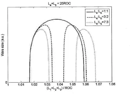
Figure 2.10 Beam waist size inside the crystal vs. total propagation length in the collimated arms ... ... 47
Figure 2.11 Beam waist size inside the crystal vs. total propagation length in the collim ated arm s ... 47
Figure 2.12 Astigmatism compensating angles for two curved mirrors; d is the distance from the crystal surface near Mirror 1 to the location of compensation... 49
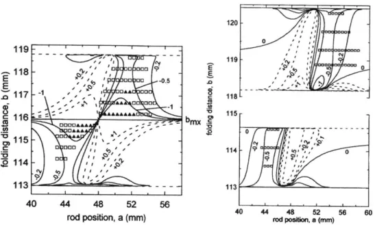
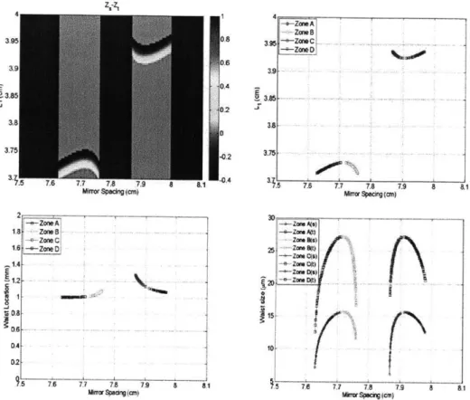
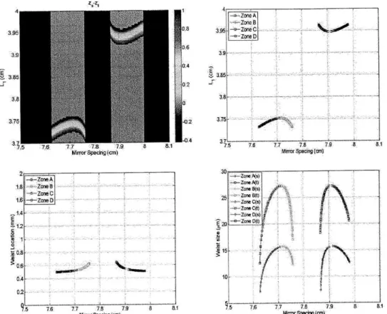
Figure 2.13 Region of stability for the 85MHz linear cavity without (left) and with (right) astigmatism compensation... 49 Figure 2.14 Analysis of astigmatism-compensated cavity with d=0.5L2. (Top-left) Difference in real part of the self-consistent q-parameter at the crystal surface close to the mirror M, between sagittal and tangential plane. The value is normalized to the total crystal length L2. (Top-right) LI vs. mirror spacing for astigmatism-free operation. (Bottom-left) waist location inside
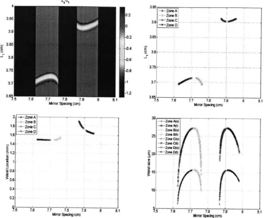
the crystal for astigmatism-free operation. (Bottom-right) Waist size vs. m irror spacing... ... ... 51 Figure 2.15 Analysis of astigmatism-compensated cavity with d=0.25L2. (Top-left) Difference in real part of the self-consistent q-parameter at the crystal surface close to the mirror M, between sagittal and tangential plane. The value is normalized to the total crystal length L2. (Top-right) Li vs. mirror
spacing for astigmatism-free operation. (Bottom-left) waist location inside the crystal for astigmatism-free operation. (Bottom-right) Waist size vs. m irror spacing... 52
Figure 2.16 Analysis of astigmatism-compensated cavity with d=0.75L2. (Top-left) Difference in real part of the self-consistent q-parameter at the crystal surface close to the mirror M, between sagittal and tangential plane. The value is normalized to the total crystal length L2. (Top-right) LI vs. mirror spacing for astigmatism-free operation. (Bottom-left) waist location inside the crystal for astigmatism-free operation. (Bottom-right) Waist size vs. m irror spacing... 53
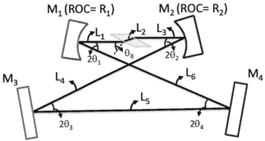
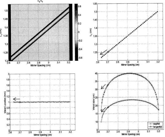
Figure 2.17 Analysis of astigmatism-compensated ring cavity with d=0.5L2. (Top-left) Waist location difference between sagittal and tangential plane. (Top-right) LI vs. mirror spacing for astigmatism-free operation. (Bottom-left) waist location inside the crystal for astigmatism-free operation. (Bottom-right) Waist size vs. mirror spacing. The red mark shows the current operating point and the arrow shows the desired direction of optimization... 54 Figure 2.18 Geometry of a 2GHz ring cavity operated at an astigmatism-free operating point (marked in red in Figure 2.17). Points A-F indicate the position of each components that the cavity mode hits on... 56
Figure 2.19 Change in cavity mode path when moving the laser crystal and one mirror by * x and 2 - x in the same direction. Points A'-F' indicate the new position that the cavity mode hits on... 56
Figure 2.20 Schematic showing how to compensate for the cavity beam path change. When both flat mirrors are tilted clockwisely, the cavity mode could hit the original positions A-F except point E and the cavity is operated at the astigmatism-free point again. ... 56
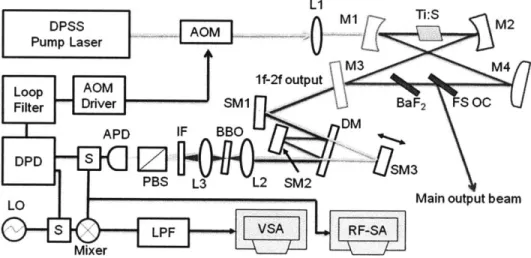
Figure 2.21 Concept of soft-aperture Kerr-lens mode-locking... 58 Figure 2.22 Reflectivity and group delay for a typical double-chirped dispersion compensating mirror pair used in the octave-spanning Ti:Sapphire laser. The high reflectivity band extends from 600 - 1200 nm, with a region of extremely low reflectivity near 532 nm to allow transmission of light from the pump laser. In the lower portion of the graph is the designed and measured group delay for each mirror as well as the average value. ... 60 Figure 2.23 Setup of CE phase stabilized octave-spanning Ti:sapphire (Ti:S) laser and phase-locking electronics. The four-mirror cavity is formed by two pairs of DCM, (Ml,M2) and (M3,M4). M1 and M2 are concave mirrors (ROC=2.5cm). M4 is a convex mirror (ROC= 50 cm). AOM, acousto-optic modulator; L1, pump lens (f= 4 cm); FS OC, wedged fused silica output coupler; SM1-3, silver mirrors; DM, dichroic mirror; L2-L3, lens (f=20mm); IF, interference filter centered at 580nm; PBS, polarization beamsplitter; APD, avalanche photodetector; DPD, digital phase detector; S, power splitter; LO, local oscillator; LPF, low-pass filter; VSA, vector signal analyzer; RF-SA, RF spectrum analyzer... 63 Figure 2.24 Calculated total intra cavity GDD (red solid curve) and individual GDD for each component including 2.2mm Ti:Sa (black dashed curve), 1.83mm BaF2 (purple short dotted curve) , 2.12mm FS (blue short dashed curve), 15cm air (green dotted curve), and 2 DCM pairs (gray dash dotted curve)...65 Figure 2.25 RF spectrum of pulse train detected with a 10 GHz photo detector: With high
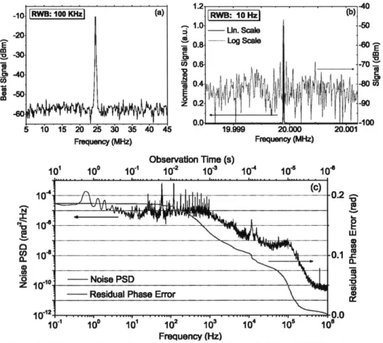
resolution at the fundamental repetition rate of 2.166 GHz; inset shows full spectrum up to 16 GHz... 66 Figure 2.26 Output spectra of (a) lf-2f output beam (black curve) and (b) main output beam (red curve) from the laser. The filled area between two curves visualizes that the spectral components of 1f-2f output below 600 nm and above 1120 nm are stronger than in the main output... 67 Figure 2.27 RF spectrum of the free-running CE-beat (RWB = 100 kHz) showing a SNR of -50 dB. (b) RF spectrum of the locked CE-beat signal in log scale (red dotted curve) and linear scale (black solid curve) showing a resolution-limited linewidth of 10 Hz. (c) Power spectral density (PSD) of the residual
envelope phase fluctuations (black curve) and integrated carrier-envelope phase error (red curve). The accumulated phase error integrated from 0.1 Hz to 1 MHz is 0.187 rad... 70
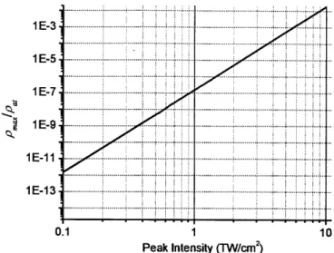
Figure 3.1 Maximum plasma density generated from a 10fs pulse of different peak intensity. ... ... ... 80
Figure 3.2 Nonlinear coefficients for Kerr effect, MPA, and plasma effects as a function of peak intensity assuming a lOfs pulse. ... 80
Figure 3.3 Numerical procedure of RK4P ... . ... 86
Figure 3.4 Concept of adaptive step-size control... 87
Figure 3.5 Schematic of a typical unfolded cavity path (top) and its equivalent system (bottom) for efficient simulation of the beam propagation outside the crystal.
... 89
Figure 3.6 Setup of a 2GHz four-mirror ring cavity Ti:sapphire laser used for simulations and experiments. ... 93
Figure 3.7 The temporal evolution of the pulse inside the crystal for every 50 round-trips from initial to steady state. ... 96
Figure 3.8 The evolution of laser spot size and its overlap with the pump beam inside the crystal for every 50 round-trips from initial to steady state... 97 Figure 3.9 The steady-state pulse spectrum for an ideal dispersionless laser cavity. The transform-limited pulse duration is 6.17fs... 98
Figure 3.10 Spectral evolution (log scale) of the intracavity pulse vs. number of round-trips. The figures are obtained with an initial pulse of (left) 100fs and (right)
lOfs ... 99
Figure 3.11 Comparison of local error convergence using a long (100fs) and a short (10fs) initial pulse. Once the pulse transients die, the error converges linearly.
... 100
Figure 3.12 Region of stability of the simulated laser cavity. The laser is operated at the edge of shorter mirror spacing with a waist size of 20-25 - m... 101 Figure 3.13 The steady-state laser spot size and its overlap with the pump beam inside the crystal as a function of cw laser waist size from 20 - 25 - m... 101
Figure 3.14 Peak intensity of the pulse inside the laser crystal. ... 102
Figure 3.15 Intracavity spectrum of the steady-state pulse with different operating points of the laser... 102
Figure 3.16 Accumulated nonlinear phase vs. operating point at different pumping pow ers. ... 103
Figure 3.17 Maximum intensity vs. operating point at different pumping powers... 104
Figure 3.18 Intracavity pulse energy vs. operating point at different pumping powers. 105 Figure 3.19 Convergence of local error for different operating points with a pump power of 8W ... ... 105
Figure 3.20 Transform-limited pulse width vs. net cavity GDD ... 106
Figure 3.21 Simulated intracavity pulse energy vs. net cavity GDD... 106
Figure 3.22 Simulated intracavity laser spectrum vs. net cavity GDD... 107
Figure 3.23 Wavelength-dependent beam profile of a mode-locked beam from a cavity with a net GDD of 0, -2, -5, and -10 fs2 .... . . .. . .. .. . .. .. . .. .. . .. .. . 108
Figure 3.24 Simulated intracavity laser spectrum for net cavity TOD of -2, 0 and 2 fs3. The net cavity GDD is set to 0 fs2... . .. .. . .. . .. .. . .. .. . .. .. . .. .. . 109
Figure 3.25 Wavelength-dependent beam profile of a mode-locked beam from a cavity with a net TOD of 2 and -2 fs3... . .. .. . .. .. . .. . .. .. . .. .. . .. .. . .. ... 109
Figure 3.26 Measured beam profile at different wavelengths from a DCM-based ring cavity Ti:sapphire laser... 110
Figure 3.27 Cavity round-trip phase from dispersion... 111
Figure 3.28 Simulated wavelength-dependent spatial beam profile of the laser beam from a DCM-based ring cavity Ti:sapphire laser... 111
Figure 3.29 Comparison of measured and simulated spectra from a DCM-based ring cavity Ti:sapphire laser... 112
Figure 3.30 (Top) Zoom-in of the resonant peaks near 650 nm of the simulated. spectrum. (bottom) cavity round trip phase - D from dispersion. The color plots on the right show the beam profile corresponding to the phase-matched w avelengths... 114
Figure 3.31 (Black solid) Round-trip phase from a cavity with 0 fs2
GDD and -2 fs3 TOD. (Red dashed) engineered phase for enhancing side-band generation using the phase-m atching concept. ... 115
Figure 3.32 Simulated output spectra for (1) original cavity (Black), (2) cavity with phase-matching phase in long wavelength wing (Red), and (3) cavity with phase-matching phase in both wavelength wings (Red)... 116 Figure 3.33 Simulated wavelength-dependent spatial beam profile from a phase-matched laser. Fundamental modes are generated for the If (1 140nm) and 2f (570nm) w avelengths ... ... 117 Figure 3.34 Simulated output spectra with different output coupling for the If and 2f w avelengths ... ... ... 117 Figure 3.35 Simulated wavelength-dependent spatial beam profile from a phase-matched laser with different output coupling for the if and 2f wavelengths: (1) 10%, (2) 30%, (3) 50%, and (4) 100%. When the output coupling is higher, the beam becomes more structured... 118 Figure 4.1 (a) Gain profile of Ti:sapphire crystal (dashed black) and the designed transmission (solid red) and group delay (dashed blue) of inverse-gain output coupler; (b) Layer structure of the gain-matched output coupler design. The layers are numbered from top (free-space) to bottom (substrate)... 121 Figure 4.2 Measured beam profile of mode-locked Ti:sapphire laser when operated at (a) center of stability region with gain-matched output coupler and (b) edge of stability region with traditional output coupler without an interference filter and after 10 nm filters centered at 570 nm, 900 nm, and 1140 nm... 123 Figure 4.3 (a) Intracavity and (b) output optical spectrum generated at different pump pow er levels... 124 Figure 4.4 (a) Intracavity and output pulsewidth at different pump power levels (left axis) and the corresponding output power (right axis). (b) Calculated intracavity pulse energy vs. intracavity pulsewidth. Dashed curve shows pulsewidth that is inversely proportional to the pulse energy. ... 126
Figure 5.1 The PCF's group velocity dispersion and calculated coherent length for three fundamental solitons with different peak power or center wavelength (see the legend). L,, labels the continuum length for the blue curve... 133 Figure 5.2 Spectrum evolution along propagation distance for fundamental solitons with different FWHM duration. The spectrum intensity is shown in logarithm scale. The double-arrow line marks the continuum that connects the phase-matching wavelength and the soliton center wavelength... 135 Figure 5.3 Spectrum evolution along propagation distance for fundamental solitons with different center wavelength. The spectrum intensity is shown in logarithm scale. The double-arrow line marks the continuum that connects the phase-matching wavelength and the soliton center wavelength... 135 Figure 5.4 Dependency of FOCR conversion efficiency on input pulse duration for different pulse energy. An optimum duration in maximizing conversion efficiency exists for a given input pulse energy; the optimum duration becomes shorter with increasing pulse energy. The orange dashed line indicates the duration that corresponds to a pulse of 10 cycles centered at 0.8 pm ... 139 Figure 5.5 Evolution of FOCR conversion efficiency and spectral bandwidth along propagation distance for a 10-fs hyperbolic secant pulse centered at 0.8 pm with 300-pJ pulse energy. Insets (a) and (b) plot spectra corresponding to the maximum and minimum bandwidth. Further propagation of spectrum recorded in (b) up to 2 cm results in the FOCR spectrum shown as the blue, solid line in inset (c). If we propagate only the FOCR spectrum (i.e., spectrum in 0.4-0.6 pm), the corresponding spectrum at 2-cm distance is denoted by the red, dashed curve. See the text for details. Note that the spectra are shown in linear scale... 141 Figure 5.6 PCF dispersion and pulse spectrum after propagating a 300 pJ, 10 fs pulse through 2 cm PCF and... 145
Figure 5.7 (b) CR efficiency versus input pulse energy for three FWHM durations of the input pulse: 10 fs, 50 fs, and 100 fs... 146 Figure 5.8 Phase-matching condition for CR and group-velocity matching. The matching points between the CR pulse and Raman soliton corresponding to
15 cm and 74 cm PCF are marked, respectively, to illustrate the trapping
process. Inset shows the wavelength-dependent group-velocity normalized to the light speed in vacuum . ... 148 Figure 5.9 Evolution of FOCR spectrum with increased PCF length, labeled as 2 mm, 4
mm, 2 cm, 15cm, and 74 cm, respectively. The input pulse energy is fixed at
300 pJ. Inset shows the laser spectrum coupled into the fiber (i.e., the optical
spectrum at the beginning of the PCF)... 149 Figure 5.10 Evolution of CR and Raman solitonwith increased pulse energy for 15 cm PC F ... 152
Figure 5.11 Conversion efficiency of CR and Raman soliton versus input pulse energy
... ... 153
Figure 5.12 7 dB bandwidth of CR and Raman soliton versus input pulse energy. ... 153 Figure 5.13 FOCR spectra generated by 10-cm PCFs with different ZDWs, i.e., 710 nm (red curve), 735 nm (green curve), and 750 nm (blue curve). The one with 750-nm ZDW is a polarization maintaining (PM) PCF... 156 Figure 6.1 Schematic of the two-mirror dispersion-free cavity based on (a) Bragg-stack mirror pair and (b) zero-GDD mirror pair. The curves on the right show the individual and average group delay on the cavity mirrors as a function of w avelength... 165 Figure 6.2 Structure of a two-mirror zero-GDD mirror set designed for a 40GHz FSR,
100 nm bandwidth (480-580 nm) cavity using Nb205/SiO2 layer pairs. (b)
Structure of a low-dispersion BSM mirror that is individually optimized for the same goal. (c) Calculated reflectivity (dotted curves) and group delay (solid curves) of the zero-GDD mirror pair. The total cavity group delay using the zero-GDD mirror pair (blue) is calculated by taking the dispersion of both mirrors and 7.5 mm of air into account. As a comparison, the total
GD (solid) and reflectivity (dashed) of a cavity in vacuum based on two
individually-optimized, low-dispersion BSMs is shown in green... 170 Figure 6.3 Simulated phase deviation from a dispersion-free cavity using one zero-GDD mirror pair. The deviation of the ideal zero-GDD mirror pair design is shown in black and the spread of possible phase errors with 100 tests
assuming a random manufacturing error of +0.5 nm for the mirror layer thicknesses is shown in red. (b) Estimated enhancement factors for 100, 50, 20 and 10 fs Gaussian pulses considering normally-distributed manufacturing errors with a standard deviation - , of = 0 (blue), 1 (red), and 2 nm (black). Each marker indicates shows the average value and the error bar show the standard deviation of enhancement factor for 1000 tests... 171 Figure 6.4 Experimental setup for generating a 40 GHz green astro-comb for astronomical spectrograph calibration. DCM: doubled-chirped mirrors for dispersion compensation; HWP: half-wave plate; PCF: photonic crystal fiber. (b) Input (black) and output (red) spectra before and after the 40 GHz FP filter cavity based on a zero-GDD mirror pair; inset shows detailed output spectrum near 555.4 nm obtained with a high resolution (-20 GHz) optical spectrum analyzer... 174 Figure 7.1 Microscope images of Ti:sapphire crystal surface showing different level of crystal damage. (a) crystal surface is coated with contaminates with a small burn spot in the middle. (b) a large portion of surface contaminates is burned. (c) The burned area is turned into permanent surface damage that cannot be removed with cleaning. (d) A severe damage showing a large hole surrounded by many microcracks on the crystal surface. (Note: the diameter of damaged spot is about 10 times larger than the contaminated area in the other three pictures. The microcracks can be seen with the naked eye.).... 181 Figure 7.2 Microscope image around a damaged spot on the crystal (left) before cleaning and (right) after cleaning... 182
Chapter 1
Introduction
1.1. Background
Over the past few decades, the advances in ultrafast laser technology have led to a remarkable success in generating few-cycle pulses directly from a laser. First of all, using gain materials capable of emitting very broadband light such as Ti:sapphire and other Chromium-doped crystals has opened the door to few-cycle lasers. However, due to the non-uniform gain and loss profile, laser oscillation normally occurs for just one or a few resonator modes where the saturated gain is close to the loss curve. In order to obtain a short pulse, additional mechanisms must be placed in the laser to overcome the gain filtering effect and maintain the phase coherence of a large number of lasing modes. Such process has been termed mode locking whose main goal is to create an environment that favors pulsed operation over continuous-wave operation. Since the mid-1960s, various active [1-6] and passive mode locking [7-13] techniques have been intensively studied. The results have successfully pushed the shortest pulse duration from the nanosecond to sub-picosecond regime. For the two following decades, the world of ultrafast was defined by dye lasers with colliding-pulse mode-locking (CPM) [14], [15] in the
-100fs regime. To date, the dye lasers have been replaced by Ti:sapphire laser and the Kerr-lens mode-locking (KLM) technique [16]. Since the Kerr-nonlinearity provides almost instantaneous response to the pulse intensity, it sets no limit to the shortest pulse that can be generated even with the broadest bandwidth material
-Ti:sapphire. Since the first demonstration of the KLM-Ti:sapphire laser in 1991, researchers spent more than one decade to fully explore the power of the Ti:sapphire laser. Nowadays, Ti:sapphire laser has become a commercially available tool for routine generation of sub-two-cycle or even octave-spanning pulses at various repetition rates up to GHz range.
The key to the stable mode-locking of Ti:Sapphire lasers lies in the balance of various spatial and temporal nonlinear effects such as self-amplitude modulation
(SAM), self-phase modulation (SPM), saturable absorption, self-focusing,
gain-filtering, gain-guiding, and so on. Due to the strong coupling between these effects, performing a reliable analysis and optimization become extremely challenging. Over the past few decades, various spatial or temporal theories have been developed for explaining the physics behind the operation of KLM lasers from different point of view. For example, through the introduction of an intensity dependent lens in the ABCD analysis of the laser cavity, the SAM action can be derived from the spatial variation of the beam width inside the gain crystal (for soft-aperture KLM cavity) or at the plane of a slit (for hard-aperture KLM cavity). In the time and frequency domain picture, the mode-locking dynamics can be explained using the concept of dispersion-managed soliton [17]. Due to the balance of SPM and cavity group delay dispersion (GDD), the pulse does not change its
shape after each round-trip and generate a stable output pulse. These mode-locking dynamics are linked by the optical Kerr effect which leads to self-focusing effect in space and SPM in the time domain. These nonlinear effects are more dramatic in few-cycle lasers due to much higher intracavity pulse intensity. As a result, the spatiotemporal dynamics become more complicated and the physics behind many phenomena in the few-cycle lasers has not been unveiled such as the highly structured beam profile across the entire wavelength range. Currently, the optimization of few-cycle lasers is still relying mostly on the experimental observations. To further improve these few-cycle lasers, a more accurate theory that can deal with the full spatiotemporal mode-locking dynamics of the laser should be employed.
Comparing to the lasers generating longer pulses, few-cycle lasers are more desirable for applications demanding higher intensity and shorter pulse duration. When the pulse duration is down to sub-two-cycle regime, manipulating the shape of the electric field by the carrier-envelope phase control is an important technique in electric-field sensitive applications. The broadband optical spectrum from a few-cycle laser can be used for broadband spectroscopy [18-20] or excitation of multiple fluorescence proteins [21]. For a few-cycle laser with octave-spanning spectrum, it can also be turned into frequency combs when the laser repetition rate and carrier-envelope offset frequency are both stabilized. The most common approach used for detecting carrier-envelope offset frequency is 1f-2f interferometry. This approach needs two successive nonlinear processes including either an intracavity or extracavity spectral broadening for obtaining If and 2f
components and the self-referencing involving second-harmonic-generation for producing a carrier-envelope (CE) beat note. The laser repetition rate is usually detected with a photodetector and controlled by changing the cavity length. These stabilization processes turn a laser into an optical flywheel that can transfer the frequency stability from a microwave source to the optical frequencies and provide unparallel fractional frequency stability. Frequency combs are also versatile tools for stable and accurate measurements in frequency metrology, time resolved and frequency-domain spectroscopy [22], optical arbitrary waveform generation (OAWG) [23] and calibration of astronomical spectrographs [24]. To enable more compact and more powerful frequency comb systems, ultra-broadband laser oscillators operating at high repetition rates are highly desired. For frequency metrology and spectroscopy, higher repetition rates correspond to larger mode spacing, higher power per mode, and higher signal-to-noise ratio. In OAWG applications, high repetition rate enables the use of lower resolution spectral dispersers. The well-defined comb lines from a high-repetition-rate frequency comb also serves as an excellent frequency ruler for calibrating an astrophysical spectrograph. By mapping the CCD pixels with the laser comb lines with known frequencies, radial velocity measurements with unprecedented precision - 1 cm/s
may be achieved. This will enable the determination of the mass of sub-Earth-mass exoplanets by the Doppler shift resulting from the reflex motion of the parent star around the common center of gravity. The Doppler shift sensitivity enabled by the blue astro-comb will make it possible to determine the properties of a broad spectrum of exoplanet systems including their geology as well as the detailed
properties of the stars they orbit. Such astronomical optical spectroscopy (also known as astro-comb [24]) is an essential tool for addressing two of the leading questions in science today: the existence and distribution of life throughout the universe and the dynamics and nature of dark energy. A crucial enabling technology for these investigations is an ultrastable, broadband, high line-density, bright wavelength calibrator that can be deployed flexibly and reliably at ground based observatories. The technology to build such a calibrator can be realized by integrating an octave-spanning mode-locked femtosecond laser with a Fabry-Perot filtering cavity, which produces a set of bright, regularly-spaced emission features in frequency domain. To realize such an exciting application for exploring earth-like planet, the development of broadband filtering cavity and a high-repetition rate frequency comb based on high-performance, easy-to-operate, and long-term stable few-cycle lasers are necessary.
1.2. Overview of the Thesis
This thesis is organized as follows: In chapter 2, the essential background reviews as well as key concepts in KLM lasers will be given. The design guideline as well as the main challenges for practical ultrabroadband Ti:sapphire laser will be discussed. Finally, an octave-spanning Ti:sapphire laser with the world's highest repetition rate will be demonstrated. In chapter 3, a numerical model for simulating the full spatiotemporal dynamics is introduced. The NLSE dominating the nonlinear propagation process of the pulse in the few-cycle regime is derived. To enable efficient numerical calculation, GPU accelerated computing techniques are adopted. With this model, many unique features that are observed from the
experiments can be simulated for the first time. In chapter 4, a novel type of output coupler called gain-matched output coupler is introduced. The gain-matched output coupler can greatly reduce the nonlinearity required for ultra-broadband mode-locking. Already at pump power levels close to the cw lasing threshold it is possible to initiate robust mode-locking and generate <8 fs output pulses from Ti:sapphire lasers with excellent beam quality operating in the center of its stability range. In chapter 5, we study the fiber-optic Cherenkov radiation in the few-cycle regime excited by sub-10fs Ti:sapphire pulses. Through a dispersion-enginnered PCF and a few-cycle pulse, the nonlinearity can produce highly efficient broadband frequency up-conversion to the visible wavelength range. The technique has enabled the constructions of visible astro-combs. In chapter 6 we have proposed and demonstrated a new approach for broadband dispersion-free optical cavities using a zero-GDD mirror set; e.g., to enable laser frequency combs for pulse repetition-rate multiplication and pulse enhancement. With a first zero-GDD mirror pair design, the construction of a -40 GHz filtering cavity with 100 nm bandwidth for a green astro-comb (480-580 nm) was demonstrated. By proper structure scaling and re-optmization, the spectral coverage of the zero-GDD mirror set can be easily shifted to other wavelengths. We believe this technique can also enable many other frequency-comb-based applications that demand large comb spacing or high peak intensity. Finally, the thesis is concluded by discussing the practical issues related to the construction of a easy-to-operate, long-term stable few-cycle Ti:sapphire laser. Possible routes for further improvements will be suggested.
Chapter 2
Ultrabroadband Ti:Sapphire Lasers
2.1. Introduction
This chapter provides the essential background reviews as well as key concepts in KLM lasers. We also discuss design guidelines and main challenges for an practical ultra-broadband Ti:sapphire laser. As an example, we demonstrate an octave-spanning Ti:sapphire laser with the highest repetition-rate.
2.2. Brief Review of the Laser Basics
LASER, an acronym originally for the process of Light Amplification by
Stimulated Emission of Radiation, is now generally used to represent the light with high degree of spatial and temporal coherence or the device that emits such type of light. Unlike the natural processes such as incandescence (hot body radiation) and luminescence (cold body radiation) that radiate incoherent light, laser only allows the emission of photons from a finite number of resonant modes predefined by the laser cavity. As a result, the laser light exhibits predictable and controllable behavior that can be used to sense, characterize, or even change the properties of materials in its path. This property makes laser a powerful tool for both scientific
and industrial purposes. This section is devoted to a brief review of laser properties as well as presenting the convention used throughout the thesis.
2.2.1. Plane Wave: The General Solution of the Helmholtz
Equation
Since lasers emit electromagnetic waves, it is appropriate to start from the well-known Helmholtz wave equation derived from the Maxwell's equations (assuming the medium is nonmagnetic, i.e. p-po)
V2 2E
= p -E
a2(2.1)
The general solution of the equation is a linearly-polarized plane wave propagating along one direction (e.g. z-axis),
E(z,t) = E cos(ct - kz + #)n, (2.2)
where
n
is a unit vector in the transverse plane whose orientation is the polarization of the wave, co the angular frequency, and k the propagation constant satisfying the dispersion relation22
k2
2 2'7 (O2-3)where n is the refractive index of the material and c is the speed of light. In the form of a monochromatic wave, solution (2.2) can be used to compose the light field radiated from an ideal laser. To take the advantage of Fourier analysis, it is usually rewritten using a complex notation
where the phase
#
has been incorporated into the complex scalar E0 and the frequency-domain representation of the complex field can be calculated by Fourier transform defined as:A1 00
E(z,co)=- jE(z,t)e-'dt (2.5)
2;r
-In this notation, the laser beam intensity I, i.e. the magnitude of time-averaged Poynting vector, can be computed as:
I
= cocn E0 2 (2.6)
The results can be extended to circularly and elliptically polarized waves as they are the superposition of two orthogonal linearly-polarized waves in the transverse plane.
2.2.2. Paraxial Approximation and Gaussian Beams
In the cases considered here, the beams are paraxial. In the simplest case where only a monochromatic beam with a finite transverse extent is used, the optical field can be conveniently represented as a superposition of plane waves with an angular frequency co and a propagation vector close to the direction of energy flow defined as z-axis. Mathematically, it is then useful to write a general solution in the form of
E(x, y,z,t) = Eou(x, y,z)eia"-"v (2.7)
The solution u(x,y,z) must obey the Helmholtz wave equation (2.1), resulting in the well known paraxial wave equation (PWE)
V2u -2jk -=0 (2.8)
where V2 is the transverse Laplacian and u(x,y,z) is assumed to be slowly varying along the z-axis. The PWE has Gaussian beam solutions. The fundamental
Gaussian beam uoo is written as
u00(x, y,z) ~ e 2y (z)e,,2ek(X2+Y )/2 2 R(z) ej#(z) b (2.9) w(z) ZR
Figure 2.1 Diagram of a fundamental Gaussian beam.
The important parameters of a Gaussian beam can be summarized as follows (see Figure 2.1): wo = R w(z)= wO 1+ -Z 2R (2.10) (2.11) (2.12) (2.13) R(z) 2
+z
Rz $(z)= tan-1 ZRwhere A is the wavelength of the light, z the relative position along the propagation axis, 2
ZR the confocal parameter (known as depth of focus) defining the region
where the beam radius w(z) is less than
45
times of the beam waist radius wo, R(z) the radius of curvature of the phase front, and#(z)
the Gouy phase shift. These features are related to a complex beam parameter q given byq = z + JZR (2.14)
In Gaussian beam propagation, the q parameter is very useful for describing the beam evolution through an optical system composed of lenses, mirrors, tilted plates and even a laser cavity formed by a number of optical components. The effect of an optical system on a Gaussian beam can be determined by a bilinear transformation of q using the ABCD matrix approaches:
- Aq,, + B (2.15)
Cq, + D
The generalized ABCD matrices describing propagation, refraction, and reflection of Gaussian beams are shown in Table 2.1.
Element Sagittal Ms Tangential MT
Propagation in 1 d
a medium with
constant n ( 1
0 Vn, 2 -sin2 0. 0
Refraction at a
2n, cosJ0
curved interface co - n -si nr Cos j- n,2 - sin 20 i Cos e,
MB(Gi, nr, R) R-cos jn, --sin
Reflection at a 1
curved interface
1
0
-2cosoy
0
J
Mc(6, R)
Table 2.1 Generalized ABCD matrices for propagation, refraction, and reflection.
R is the radius of curvature of the interface, 9, is the angle of incidence, nr is the
refractive index ratio of the output medium to input medium.
For most optics used in common linear optical systems such as lenses, mirrors, optical windows, and prisms, we can find their ABCD matrix using a combination of these three matrices. For example, the ABCD matrices of a Brewster window of thickness t in the tangential and sagittal plane are given by
2n*2-9sin2
n, - sinf2
1,2
MBPT n,cos, 1 1 d nCOS0,, (216) 0 CS 0,,21 0 17 0 CS 0,J 2 n - in2 n, _n,2 -sin2(1
0 (1 0 MBP,s = 0 n,) 0 1)4r (2.17)where nr is the refractive index ratio of the plate to free space and d is the path length. OB,12 and GB,21 are the Brewster angles in the free space and the plate.
0B1 = tan-' (n) (2.18)
6B,12 r) -.
d = t (2.20) COS OB,12
2.2.3. Optical Resonators
Self-consistent q-parameter
To solve the resonant modes supported by a laser cavity, one can calculate the
overall ABCD matrix by multiplying the matrix of each individual component in one round-trip. The ABCD matrix is calculated from an arbitrary plane of interest (i.e. reference plane). For a stable mode, the field must reproduce itself after every round-trip, i.e.
=Aq+ B
q= +(2.21)
Cq + D
With the fact that AD - BC = 1, the self-consistent q parameter is then given by
q= + - 1- : (2.22)
2C
C|
2The stability condition is obtained by requiring that q must have nonzero imaginary part, i.e.
-2 (A+ D) ! 2 (2.23)
Longitudinal Modes
Once the q parameter on a reference plane is found, the structure and the round-trip Gouy phase shift of the resonator mode across the entire cavity can be obtained. The round-trip Gouy phase is required to analyze the frequency of the longitudinal