DEVELOPING ARCHITECTURAL VISUALIZATION USING VIRTUAL ENVIRONMENTS
by
ALLISON M. STAMIDES, R.A. B.Arch. University of Miami
1988
SUBMITTED TO THE DEPARTMENT OF ARCHITECTURE IN PARTIAL FULFILLMENT OF THE REQUIREMENTS
FOR THE DEGREE OF
MASTER OF SCIENCE IN ARCHITECTURE STUDIES AT THE MASSACHUSETTS INSTITUTE OF TECHNOLOGY
June 1996
Copyright C 1996 Allison M. Stamides. All rights reserved.
The author hereby grants to M.I.T. permission to reproduce and to distribute publicly paper and electronic copies of this thesis document in whole or in part.
Signature or Author: Allison M. Stamides Department of Architecture May 10, 1996 Certified by: William J. Mitchell Dean, School of Architecture and Planning Thesis Advisor
Accepted by:
Roy Strickland Associate Professor of Architecture Chairman, Department Committee on Graduate Studies
MASSACHUjS~r7 INSTITUTE
JUL 19 1996
LISRAHIL$COMMITTEE READERS
William L. Porter Professor of Architecture
Julie Dorsey Assistant Professor of Design and Computation and Building Technology.
DEVELOPING ARCHITECTURAL VISUALIZATION USING VIRTUAL ENVIRONMENTS
by
ALLISON M. STAMIDES, R.A.
Submitted to the Department of Architecture on May 10, 1996 in partial fulfillment of the requirements for the degree of Master of Science in Architecture Studies
ABSTRACT
This thesis anticipates the emergence of virtual reality (VR) technology as an economical alternative to architectural presentation. As professionals, designers are trained to interpret two dimensional media spatially. Experience has shown that client (or user) interpretation of traditional media (two dimensional drawings and physical models) has led to discrepancy. Controlled two dimensional media may also serve as a seduction, often portraying unrealistic views. In the case of highly technical spaces, participatory design is a necessity. Successful communication of need and intent are critical to the overall success of the project in concept and in detailed design. The smallest error in communication may result in costly penalties, often at the expense of an architectural amenity or in material quality.
This investigation attempts to eliminate the need for client translation by providing a more intuitive design environment via VR. The goal is to examine several types of environments/scenarios and to design an experiential/interactive environment, three-dimensionally linking the user to the designer's solution and thought processes. Shared models will be posted over a network using VRML (Virtual Reality Modeling Language). The client will be able to use the model as a reference "book" by hyperlinked information attached to model geometry. Projects (not yet built) would be viewed at full scale (some in total immersion), from the same perspectives of their future reality i.e., allowing the client and designer to interact within the space during the design process.
The intent is not to entirely recreate reality or to automate what is now performed manually, but to immediately express thought in a three dimensional world, enhancing collaboration and critique. The pursuit of this thesis is based on a theory which alters the conventional design-communication process to dynamically and positively impact the final product. Final data analysis will examine the process of creating and employing simulated environments for architecture, the pros/cons of implementing such a system, and the feasibility. The conclusion will recommend improving processes, systems, and the techniques employed for future "world building" of
architectural space.
As operating systems become more economical and simultaneously more powerful, computer modeling will enhance visualization. The design process approach will then turn from the "bird's eye/plan view" to the eye level perspective view. The model itself will evolve with the design as experiential scenes to ultimately be used as a design tool, as a communication tool, and perhaps finally as a resource --as cad and database information are linked today.--to be accessed throughout the project life cycle.
Thesis Advisor: William J. Mitchell
ACKNOWLEDGMENTS
For my parents,
Mary Ann N. and Theodore G. Stamides, to whom I owe all things.
....and in memory of my little brother George, who I love and miss.
My sincere thanks to my advisor William J. Mitchell, to Owen D. Johnson without whom this study would have never been completed, to The MIT Research Lab for Bectronics, to Jeffrey C. Krause for unselfishly sharing his time and knowledge, to the staff of the U.S. Army Health Facility Planning Agency, and especially to Colonel CEM Maxwell for his support in helping to make this dream a reality.
CONTENTS
Abstract 3
List of Figures 7
List of Tables 8
Preface 9
1. Introduction to the Problem 10
1.1. Problem Solving Proposals 13
1.2. Clarification of Terms 15
1.3. Introduction to VRML 18
1.4. Existing Technologies (pro/con) 20
2. Translating 2D Media to 3D Objects 20
2.1. Perspective and Perception for Learning 20
2.2. Representation Media and the Benefits of Total Immersion 22 2.3. Altering the Conventional Design Process -Client communication 22
3. System Implementation 23
3.1. File Formats 23
3.2. Building Cyberspace -VRML and its Extensions 24
3.3. The Future of Networked Simulations 26
4. The Balance Between Realism and Economy 27
4.1. High-end vs. Desk-top 27
4.2. Notes on Complexity/Maneuverability -Material/Lighting 27
4.3. Managing Levels of Detail 29
5. Experiment 1. (Perception of the Synthetic) 30
Perception of space in total immersion
5.1. Goals 30
5.2. Process 30
5.3. Findings 34
5.4. Conclusions & Residual Data 36
6. Experiment 2. VRML and Practical Applications 36
6.1. Final Design 36
6.1.1. Program 38
6.1.2. Process and Parameters 38
6.1.3. Designing and Implementing the Environment 39
6.1.4. Data Collection 42
6.2. Multi-User Environments 47
6.2.1. Process and Parameters 47
6.2.2. User Interaction and Comparison of Environments 48
7. Experiment 3. 50
Using Total Immersion to Impact the Architect's View
7.1. Exploration of Unbuilt/Work in Progress 50
7.1.1. VR, Hyperlink Technology & the Three Dimensional Archive 52
7.2. Student Abstract Design 53
7.2.1. The Secondary 3D sketch 54
7.2.2. Before and After Experience Comparison 55
8. Compilation of Views 59
8.1. The Medium is the Controversy 59
8.2. Benefits of Ambiguity and Interpretation 61
8.3. Comparison of Perceptions 62
8.4. Project Feasibility Recommendations for Future Research 63 Appendix A- Technical data 1, [chapter 5] Immersive Environment 64 Appendix B- Sample questionnaire for experiment 1 [chapter 5] 65 Appendix C- Technical data 2 [Outline for Creating VRML for Architecture] 67 Appendix D- Clarification of Color Images for Archival Purposes 76
FIGURES
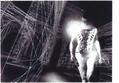
Figure Numberal. Archeology of a mother tongue(1993) by Toni Dove & Michael Mackenzie...9
1.1 computer simulation of room with luminaire... ... ... 12
1.2 computer simulation of room with coded illuminance values...12
1.3 diagram -traditional design process... 14
1.4 diagram -proposed design process... 14
1.5 diagram -objective -possible future design process...14
1.6 Photograph of Virtual 10 Head mounted display...16
1.7 Advertisement by Virtual 10 showing HMD being worn...16
1.8 Image of apparatus being worn (PC Magazine, 14 Mar 95)...17
1.9 Image of data glove -advertisement "The Pinch"...17
2.1 computer generated perspective views from Shepard/Metzler study...21
2.2 Pair of perspective views used in Shepard study...21
3.1 Views of multi-user world with two avatars occupying the space "Cybergate"...26
3.2 Views of multi-user world with two avatars occupying the space "Cybergate"...26
5.1 Participant in apparatus with views captured on monitor...30
5.2 Screen captures of Model 1 HMD views... 33
5.3 Screen captures of M odel 1 HM D view s...33.
5.4 Screen captures of Model 2 HMD views... 33
5.5 Screen captures of Model 2 HMD views... 33
5.6 Screen captures of Model 3 HMD views... 33
5.7 Screen captures of Model 3 HMD views... 33
5.8 Test subject in apparatus... . . 35
5.9 Test subject being interviewed in actual space...35
6.1 View within the designed Web environment...40
6.2 View within the designed Web environment...40
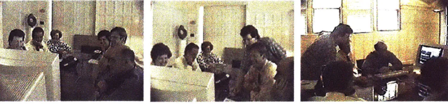
6.3 Conceptual stills used in combination w/ real-time simulation...41
6.4 Conceptual stills used in combination w/ real-time simulation ... 41
6.5 Conceptual stills used in combination w/ real-time simulation ... 41
6.6 Screen capture of real-time simulation ... 41
6.7 Video capture of architectural project team interacting with environment ... 43
6.8 Video capture of architectural project team interacting with environment ... 43
6.9 Video capture of architectural project team interacting with environment ... 43
6.10 Screen captures of environment testing via video teleconferencing...44
6.11 Screen captures of environment testing via video teleconferencing ... 44
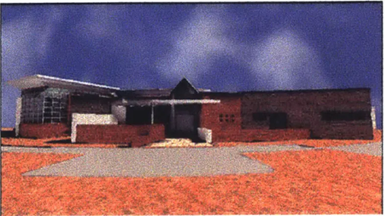
6.12 Com puter rendering of front elevation ... 44
6.13 View of clinic space within multi-user world ... 49
7.1 Participant in apparatus with views captured on monitor ... 50
7.2 Screen capture of interactive VR views (main interior Mikveh)...50
7.3 Screen capture of interactive VR views(view down into main space, Mikveh)...50
7.4 Screen capture of interactive VR views(view up into cylinder-54', Mikveh)...50
7.5 Observing design for the first time immersed ... 53
7.6 Observing design for the first time immersed ... 53
7.7 Observing design for the first time immersed ... 53
7.8 Flyover of scene 1 -columnar generator ... 54
7.9 Scene 2 - highly rendered -slightly above ground plane ... 56
7.10 Scene 2 -highly rendered -slightly above ground plane ... 56
7.11 Scene 2 - flyover ... 56
7.12 Scene 2 -observing retail with head placement inside geometry ... 56
7.13 Scene 3 -view s of structure build below ground plane ... 57
7.14 Scene 3 -view s of structure build below ground plane ... 57
7.15 Scene 3- flyover w ith low lighting ... 57
7.16 Scene 3- flyover w ith low lighting ... 57
7.17 Scene 3 -peering down between tower-like objects ... ... 57
7.18 Scene 3 -Perspectives between towers near base... 57
7.19 Scene 4 -at ground plane ... 58
7.20 Scene 4 - Observing com plexity ... 58
8.1 Liquid Architecture by M arcos Novak ... 61
TABLES
5.1 Site Recognition ... 345.2 Striking differences between synthetic and actual ... 34
5.3 N oticed changes in M odel 2 ... 34
5.4 Noticed changes in M odel 3 ... 34
5.5 Recognition of light source ... 34
5.6 Synthetic space distance estim ates ... 35
PREFACE
This thesis is an exploration of current and developing computational (virtual) environments and technologies for the purpose of communicating and designing architectural form and space. It offers a series of case studies (using a variety of technological methods) to investigate the impact on visualization and communication in search of how existing tools may be combined for use in a professional setting today.The projection into an imagined space or a sketched space is common place to design professionals but rarely to those who are presented to. The architectural "model" as a representation of built form, no matter how abstract, serves as a communicator of thought. As architects we employ the physical model to confirm the expectations of an original sketch and to solidify thought for a presentation to others. The intriguing aspect of using simulated models or those built with vectors and points, is that they are unlimited to change. Change is the catalyst of design thinking and should therefore embrace the basis of the technology. Once built, a physical model must be dismantled, preprogrammed for very limited change (i.e. plug in sections), or completely discarded to be built again, making it resistant to change. The computational model has increased in value since it is now possible to accurately simulate the affects of lighting and materials, as well as physically link it to other forms of data.
Returning to the revered sketch, some of the most provocative and informative sketches are those which are extremely minimal ["less is more"]. Certainly there are many cases when two dimensional media are more appropriate to explain a concept especially when that concept is linear. Dynamic form and space however, are rarely linear. Since technology has developed to allow more varied and vivid options in representing ideas, perhaps we should reexamine our traditional processes to ensure we are not overlooking a more effective method in favor of habit alone. In doing so, we may incorporate lessons learned from the sketch to communicate what is necessary, perhaps minimally.
Fig. al.
Archeology of a Mother Tongue (1993) By Toni Dove and Michael Mackenzie (Moser, 1996)
1. Introduction to the Problem
The issues and cases being addressed are aimed at 1) helping clients better understand architectural work during the design process, and 2) improving the design process itself by employing new methods of visualization using developing technology. During my employment I have witnessed several clients (users) request change in design during the construction phase or inquire why design decisions were made during the construction phase. Most often, these same clients were the individuals approving and/or requesting those decisions originally. It is only after the actual is constructed that the design is realized at an appropriate level by the client, in most cases. The reason for this discrepancy points towards the media used to communicate design to clients, which are most often plans, elevations, and occasionally a perspective view or a physical model. It is common knowledge that clients are often intimidated by the technical aspect of construction documents, have difficulty visualizing with two dimensional media in general, and also have difficulty orienting themselves to a physical model.
The primary reason for pursuing this study is that the mental annotation of the architectural design process (sketch, drawing, model) has also become the way in which we teach and present three dimensional thought. With recent developments in technology however, traditional methods are in flux and should be reconsidered. Architecture: a three dimensional experiential craft, is more often developed and depicted with two dimensional media. This exploration suggests an emphasis on the perspective rather than the domination of the plan.
Based on personal experience, the ideas of designers rarely come to life in the clients view until a model is presented. With this, the view is also limited since the observer is expected to project and orient themselves into the space along with a certain level of abstraction. Models which are less abstract are usually presented after the design is complete or as a final effort to display the product before construction. Regardless of the quality of the model, the issue that cannot be communicated in a physical model is the direct sense of scale and perspective in relation to the human body. Since designers can visualize and project, this is not a problem, but what is the impact on the user who is unfamiliar with the task?
Aside from the user view we should also begin to address the problem of improving the integration of computation and design. Most often, the issues regarding computation and design are associated with CAD technologies. Although Computer Aided Design has not revolutionized the way in which we design it has greatly impacted the way in which we conduct business. With the combined newly developed visualization tools which complement it, perhaps CAD is about to make its first dramatic impact in the design process, rather than in only automating drawing and in presenting final products. During the past 10 years we have seen a dramatic change in the improvement of computer generated images for architecture. During the past two years we have seen a much more dramatic popularization and development of graphic media communicated over the Internet. The focus of computation and design should now be on how those issues could and should be integrated as well as the future of
architecture as digital space (to establish "place") which is rapidly developing.
Traditionally, communication of design has been through a series of two dimensional media and three dimensional physical models. The use of the physical model as a descriptive tool has been more prevalent in education than in practice. Physical models are mainly used as either; a) mass models describing the exterior form and relationship of the building shape to adjacent structures , b) after final design as a detailed miniature of the space (usually for display rather than study), and c) in some rare cases as a mock up for special circumstances. This study proposes that the "architectural model" be propelled forward for more effective use during the design process by incorporating computation. As architects we should address this topic in order to become involved in the development of the next generation of design/visualization tools.
Recently, several other information technologies have advanced into academia and the workplace. These range from visual structural analysis tools to visual databases. The key issue here is "visual". Information that was only once available numerically, with line diagrams, and with text can now be viewed interactively and translated into a more visually effective (and sometimes spatial) form, making the impact and importance of the information more intuitive and therefore more useful. The result is a creation of a new information "type" in itself.
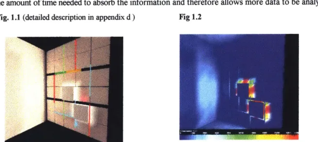
Figures 1.1 and 1.2 are simulations using the "Lightscape Visualization System" Software. A computer mock up of a room and proposed luminare were defined within a computer model. Using sophisticated parameters, the materials of the space were replicated along with the settings for the luminare in question. After processing, the simulation creates a rendering of the scene and also allows
a visual of the technical data, Figure 1.2 attaches color to illuminance values in footcandles. The
manner in which the information is presented allows a more comprehensive view of the data. Here, a great deal of information is transmitted accurately and subtly. Exposure to this type of representation, replacing (or enhancing) numerical data with color, provides the user with information while educating, making future predictions of (in this case light reaction) more intuitive. The next step toward advancing this visual analysis would be to reverse the process. In the future, a designer might interact with the illuminance number/color coding directly to alter the light which would ultimately result in automated luminare alteration. An example related to this (originally conceived at the M.I.T. Media Lab and now found in other forms on the Internet) is visual stock data, where numerical information is once again presented visually and in a third dimension. This reduces the amount of time needed to absorb the information and therefore allows more data to be analyzed.
Fig. 1.1 (detailed description in appendix d) Fig 1.2
Another data environment recently established and popularized is the creation of the World Wide Web. The "Web" as it is referred to was created by the European Laboratory for Particle Physics (on a protocol proposal by Tim Berners-Lee) and has increased in popularity "faster than any other communication media in the history of the United States" (Matsuba, 1996). According to one visionary "if the web were to expand at its current rate it would overtake the population of the planet within the next 5 years"(Negroponte, 1995). If this is true, then we must expect that the Web will
arrive at its peak exposure within the next 5 years and continue to grow not only with the population but expand by transforming into other products even more so that it has already. During the past year alone an overwhelming number of businesses have employed, been created, or have supported the World Wide Web. Advertising of a Universal Resource Locator (URL) has become commonplace wherever advertising exists, including personal calling cards. [The combination of these two new
interfaces (visual data structures and global networks) warrants reinvestigation of current practice in visualization and design communication.] Reconforming the traditional bombardment of project information is the crux of improving visualization within virtual worlds. If the visual data structure could be captured in an interactive intuitive view and utilized as the design environment, more accurate information could be accessed and employed with far greater impact.
1.1. Problem Solving Proposals
Through case study exploration, a number of environments will be tested which combine these technologies and others to communicate space from both the user and designer points of view. The cases incrementally search for lessons learned within a specific area to ultimately determine key points for building "worlds" and visualization methods. The main research tool of this study is one which has historically suffered from underdeveloped and limited debate with regard to architecture and is commonly known as "Virtual Reality". The term "Virtual Reality" is used (and over used) to describe many systems and types of synthetic environments. Its use here will be further defined in section 1.2. "Clarfication of Terms".
The theory: is that since the model is a necessary tool for learning design, it should be more integrated into the traditional design (professional practice and learning) process. [the word model here is used to define an object which represents architecturalform/space and which is or appears three dimensional and can be manipulated physically or in real timel Also, since computational models are more adaptable to change (in geometry, materials, light, etc) and can be viewed from the actual perspectives in question (and in combination with the conceptual "bird's eye view"), that they be ultimately used as the environment for the design process. By doing so, the designer and client are continuously experiencing the solution from the perspective view (as space is actually perceived), rather than the plan view. This would allow immediate witness to the effects of changes in plan and section while in perspective. Virtual environments provide an excellent research method for this
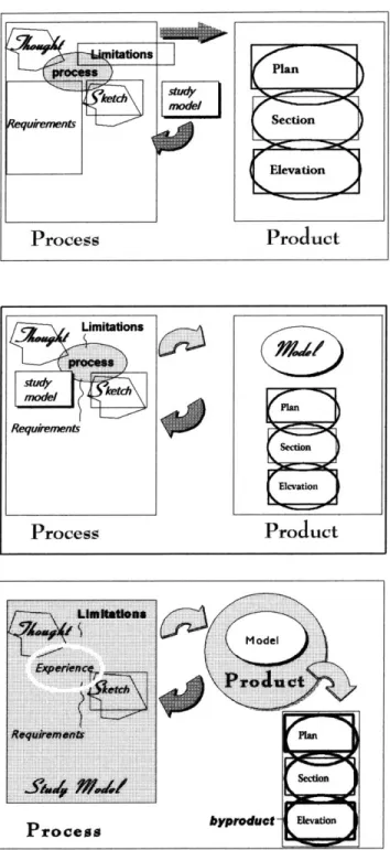
theory by visually placing the observer within a computational model and allowing the observer to interact with the environment intuitively. Figures 1.3 through 1.5 diagrammatically depict a basic outline of 1) the traditional approach to the design process, 2) the proposed approach by this study, and 3) the ultimate goal that this study points toward.
Fig. 1.3 Traditional Process
The model is secondary to the process (if employed at all). The product is largely represented by two dimensional media.
Fig 1.4 Proposed Process
The model becomes more integrated in the process, therefore including experiential design.
The model becomes a necessary part of the product.
Fig 1.5. Ultimate Process
Goal--The model-& the design environment with all parameters visible within the environment while the process is ongoing.
-The product becomes three dimensional. -The plans become the creation (byproduct)
of the three dimensional experience.
Product Process umilations Requiremnig Secon PElation
Product
ProcessThe theory contends: that creating form from different viewpoints will yield improved results. A student work developed only in plan will seem flat in experience once extruded in the third dimension. If however, we begin to enhance (or continue the process ) from the actual perspective view (rather than the predominant plan view), the results are likely to be more dynamic. If we further enhance the experience with not one, but several moving perspective views (i.e. via an interactive environment at full scale) then the results are likely to be more developed spatially and more sensitive to issues of access, view, lighting, etc. The suggestion is one that directly links plan (or section, elevation) to the actual perspective views as experienced at eye level interactively during the design process.
To explore this we may turn to existing electronic media, specifically synthetic environments, by showing:
0 the similarities between virtual space and actual space as perceived by the non-designer * how economical low level programs may be incorporated into actual projects to explore and
communicate design today
* how architects' perceptions are changed/enhanced from simulated experiences
1.2. Clarification of Terms
Before beginning it is important to define the use of the term Virtual Reality and the equipment/apparatus that will be employed. "Virtual Reality" is a term used to describe several synthetic environments. Most commonly it is "that which does not exists physically" but which is believed. In this study, Virtual Reality will be used to describe immersive environments. Immersive environments are those which encompass all views of the spectator with the synthetic or simulated environment. Therefore all head movement and views are focused on the synthetic environment with all views of the real world excluded, the individual then becomes immersed.
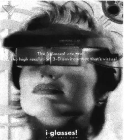
Immersion is currently achieved through a variety of apparatus. One of the most common pieces of optical display equipment associated (and faulted) with virtual environments is the HMD (Head Mounted Display) shown Fig. 1.6, 1.7. This is a visor like apparatus that presents automated views to each eye. The movement of the wearer's head is monitored by a tracking device. The tracker communicates the movement and position of the wearer's head to the computer processor(s)
allowing the appropriate view of the simulated world to be rendered inside of the HMD and to each eye. There are primarily two types of HMD's commonly available on the market, the biocular monoscopic viewer and the steroscopic viewer. Both provide two lenses however the first presents the same view to each eye while the latter presents a different view to each eye.
r
.11
g1
sss
Fig. 1.6. Recent development by "Virtual IO", Fig. 1.7. Commercial Advertisement, Light weight HMD with some external view to lessen by "Virtual 10".simulator sickness
It is reported that steroscopic viewers better represent reality since each eye view is actually different (eye parallax). The stereoscopic viewer is known to provide greater depth perception for this reason and is most effective in comprehending objects within close proximity. The HMD used throughout this study is a biocular monoscopic viewer manufactured by "VR4".
In early development the HMD was a very heavy cumbersome piece of equipment. The technology has now progressed to be very small and light weight, comparable to a visor and quickly approaching the stature of glasses. The price has also decreased tremendously and several models are now designed for the Personal Computer market, primarily aimed at computer game players and geared towards being affordable. The cost begins to increase with the quality of the resolution. The HMD has been one of the largest inhibitors of the technology. Many wearers suffer from vertigo while only in the apparatus for a short time. The nature of the simulation also limits the experience to one
person. Although piped views from the HMD maybe directed to another monitor, the immersed experience is lost to external observers. Limitations aside, the HMD is excellent for research purposes since it is economical, often high resolution, adaptable in configuration, and even portable. This study places its limitations aside since there are several other display device solutions available and currently in development. Other display devices include virtual projection, the CAVE, and the BOOM.
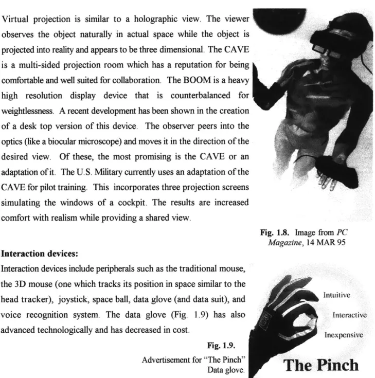
Virtual projection is similar to a holographic view. The viewer observes the object naturally in actual space while the object is projected into reality and appears to be three dimensional. The CAVE is a multi-sided projection room which has a reputation for being comfortable and well suited for collaboration. The BOOM is a heavy high resolution display device that is counterbalanced for weightlessness. A recent development has been shown in the creation of a desk top version of this device. The observer peers into the optics (like a biocular microscope) and moves it in the direction of the desired view. Of these, the most promising is the CAVE or an adaptation of it. The U.S. Military currently uses an adaptation of the CAVE for pilot training. This incorporates three projection screens simulating the windows of a cockpit. The results are increased comfort with realism while providing a shared view.
Fig. 1.8. Image from PC Magazine, 14 MAR 95 Interaction devices:
Interaction devices include peripherals such as the traditional mouse, the 3D mouse (one which tracks its position in space similar to the head tracker), joystick, space ball, data glove (and data suit), and
voice recognition system. The data glove (Fig. 1.9) has also Interactive
advanced technologically and has decreased in cost. Inexpensive
Fig. 1.9.
Advertisement for "The Pinch"
To summarize, the technologies used in immersive environments (Virtual Reality) are: M display
a tracking
a graphics processing
a interaction/navigation interface device 1.3. Introduction to VRML
On the other end of the spectrum, a system which emphasizes economy is the newly created Virtual Reality Modeling Language. This language and many of its development and viewing tools are available for free over the Internet's World Wide Web. It's creation was intended to "bring VR to the masses"(Pesce,1995). It is a lower form of environment that maybe run on a 486 processor. The result is a low to medium resolution product with varying speed in maneuverability. VRML was based on Silicon Graphics Inventor file format. It can be combined with HTML (hypertext mark up language) to link pieces of the model geometry to any other information that the Web will allow, which at the time of this writing is practically unlimited.
In terms of an immersive environment, VRML was not developed for the use although it can be adapted. VRML parsers (otherwise known as browsers or viewers) are now offered with joystick and HMD configuration allowing them to become immersive. Even in its lowest form, it is an excellent way to share models over bandwidth. Experiment 2 [Chapter 6] in this study will demonstrate an
actual building modeled in its entirety and reduced to less than a megabyte. Currently, several Schools of Architecture have developed (and are developing) student work in this format for distribution over the WWW, they include UCLA, Columbia, and the University of Washington to name a few.
The language itself, is actually a series of instructions. These instructions communicate with the browsing software, to direct how the geometry should be drawn and rendered as well as the placement, positioning, and type of lighting and cameras within the scene. The script or instructions is in this case the VRML code which lists a set of Cartesian coordinates forming the geometry, vertex ordering instructions, and viewer scene information. The parser, interprets those instructions to the rendering engine within the browsing program. The original language was meant to create simple scenes and objects by hand coding the language.
A rule of thumb given by its creators for the maximum world size is around 10,000 polygons for ease of movement within the model (Pesce, 1995). The 10,000 polygon estimate is aimed at desktop personal computing. This may obviously be increased significantly for use with an SGI, depending upon the processing power and RAM.
Other extensions of this language promise the addition of "behaviors". An organization called "Moving Worlds" was recently formed to create the next version of the specification. The goal was to improve the first specification by allowing a more object oriented world in place of an entire scene which essentially becomes one object. Some introductions to these behaviors are now available. The results allow each object within a scene to be manipulated individually in real-time. Aside from being able to navigate through an area, the observer may also become a participant by interacting with the object directly. One may interactively change color/texture of an object, move objects, change the lights within a scene interactively, or preprogram objects to include certain ranges of motion (i.e. animated objects) and the attributes of gravity.
Although the majority of this software is currently in beta, one can easily imagine its potential for use in architectural applications. Being able to interactively change a modeled scene which appears rendered adds value to the computational model over the physical model. In a future critique the reviewer (or client) might be able to see the impact of their suggested changes immediately [is this dangerous?]. If this were combined with the existing capability of immersive VRML, then we would have a very economical solution for designing within an environment from the perspective view.
In addition, the cost of viewing and development tools may be the best convincing point of all (free or under $50.00 for commercial use). This makes it a media which will be accessible to most Internet users and design firms, increasing its communication value. At the time of this writing, several model builders and rendering packages have just begun to support conversion to VRML. However, at this time, a direct conversion (which guarantees a complex geometry will be correctly read by the 3D browser) does not exist. Furthermore, most of the scenes successfully built in this format have been extremely limited in complexity. Architecturally successful scenes have been limited to very simple geometry, some texture mapping, and no detail, i.e., a room within a building, cities consisting of texture mapped blocks.
1.4. Existing Technologies Pro/Con
For research purposes this study will focus on the potential of virtual environments and the experiential concepts rather than be stifled by a critique of the current apparatus. Like its components, (i.e. processing power), the apparatus is most likely to develop in quality and decrease in cost. In terms of software, most will be obsolete prior to the completion of this writing however, it is their contribution to the theory that is the focus. Most critics of VR refuse to have any vision in the potential, and continue to dwell on the present limitations, further inhibiting its development. Virtual Reality has been used to describe systems that were once too costly and limited in use. Most believed that it may develop as a tool far in the future but that it certainly would not be affordable by architects. These misconceptions were born out of its early development stages (during the 1960's). When we revisit the technology today, we see a clear advancement to the extent of turn key marketable systems, i.e., VRML and PC based peripherals and software.
2. Translating 2D Media to 3D Objects
We cannot recreate all of the nuances of an actual environment at this time and perhaps we should not attempt to. The ambiguity of the two dimensional sketch can be translated into another forms language three dimensionally, (albeit with very different connotations) within a synthetic environment. By capturing this at progressive levels of design development, the imagination (or creative process) is supported and reenforced with visual information at an early stage rather than fully relying on two dimensional media, memory, and assumed mental rotation.
2.1. Perspective and Perception for Learning
One of the classical examples in cognitive research study was completed by Shepard and Cooper (1986) on the subject of two dimension to three dimension representation and mental rotation (Finke, 1992). The study presented a series of sketches which represented three dimensional objects. The objects were then rotated and the test subjects were asked to choose the resulting object (sketch) once rotated. The results showed the complexity of the object to be proportional to the time needed to solve the puzzle. This indicated that the method for solving the task was associated with a visualization of mentally rotating the objects. The subjects first created the objects within their minds, rotated it and then chose the result of their final vision.
Fig. 2.1. Two sets of computer generated perspective Fig. 2.2. A Pair of perspective views used in the views from the Shepard/Metzler study (Shepard/Cooper the Shepard study -views differ by 80 degrees
1986) rotation in depth (Shepard/Cooper, 1986)
While creating space, these same principles apply. The 'vision' of the designer is projected by a series of mental rotations, an understanding of the site, and future expectations (requirements). Thought is then recorded in sketch, taking on the form of parti, perspective view, plan, section, and elevation. What if these images could be captured and placed within context, on the site, while designing? The "images" would not be limited to sketch but would include desired architectural precedents, photographs, sound, objects, and anything else the imagination desired to evoke a sense of place. The combination would then become a new form of "sketch". We now have the capacity to exploit this proposal. Will it ultimately change the way we traditionally perceive or create space?
This is also an opportunity to bring others into the thought process of the designer. Accomplished successfully, (if only in part) it would make a significant contribution to the understanding of the process. This is not to suggest that the sketch be replaced in any way, it does call for the enhancement of the tools that are available. As various other graphic media evoke different qualities of style and understanding of concept, the virtual environment as a perspective design tool will also be refined to
suit the message.
Other studies have shown evidence in how mental images are constructed and understood. The experiments prove that mental images are constructed "piece by piece in a structurally coherent way"(Neisser 1967; Pylyshyn 1973)(Finke, 1992). Once a mental image is formed, experiments also indicate that they are "scanned for information" similarly to how actual objects are observed and understood (Finke and Pinker, 1982). Perhaps this is why computer animations of objects being constructed (element by element) are so effective in communication. Why not use their principles to
create a design environment which enhances mental imagery during the process? Visualization of space through virtual environments logically connects these principles and will be shown effective throughout this exploration. The next critical step will surely be the manipulation of those objects to visually construct what the mind projects, in order to share with others. Although there are currently other forms of VR which are more realistic in portrayal, (such as "Quick-Time VR"), the systems chosen for this exploration were due to the presence of object rather than image. In the systems chosen, the actual geometry is present as much as possible in anticipation of more object oriented worlds.
2.2. Representation Media and the Benefits of Total Immersion
Immersive environments present a view that is very unlike that of an animation or video. The immersed viewer projects their body into the space by associating with it visually, intuitively, and while baring all views of the actual environment. Animation, or screen viewed scenes, are alternatives to 2D representation since they are projected on a two dimensional plane. The sense of scale and intuitive viewing is obviously lost in the screen view. The animation or video also differs from the interactive model since all of the views are well choreographed and controlled by the designer or renderer. In the case of the interactive environment, views are determined by the observer, closely linking the experience with a more actual presence in the space. The interactive viewer is a
participant.
2.3. Altering the Conventional Design Process -Client Communication
Regarding client communication, there is almost a conflict of interest where some designers are concerned about involving the client to a great degree. In participatory design scenarios (of highly technical spaces for instance), client input is paramount. If we revert back to lessons learned from cognition theory we might form an opinion as to why some so called "great works" were never built. Architects continue to argue that people in the majority prefer traditional banal construction over
"good design" due to a number of reasons, two of which are: familiarity with " the traditional" and
lack of architectural understanding. Apart from aesthetic preference however, if a truly superior(but more complex) design solution is chosen over one that is lacking (but minimal in form) during design, perhaps it is because the client is indicating a threshold in understanding 2D media. Better communication of modern and/or complex forms may ultimately change what is commonly built.
3. System Implementation
To begin a basic investigation we must first understand the tools available today and their limitations. All of the computational goals I have mentioned earlier exist in one form or another but most often are limited in use since the functions are isolated within one software package or platform. This exploration as a whole, has been conducted using a variety of file structures with increasing levels of polygon intensity. This was done to expose the testers to worlds of varying speed and rendering, to finally determine how available formats will be matched with specific communication tasks.
The experiments were either conducted remotely (over the Internet, supplemented by chat sessions, conference calling, or video teleconferencing) or were completed in a laboratory using equipment with limited access. For these reasons the cases remain a series of explorations and not controlled scientific experiments.
3.1. File Formats
One of the largest problems with data sharing is the fact that systems and file formats are not likely to be compatible. This leads to the need for file conversion. Error in compatibility may occur within an upgrade of one software package alone, even though the file structure was intended to be of the same type. An example of this is the upgrade within the popular CAD program Autocad (versions 12 to 13). Here, a technological advance in the method of modeling has reduced functionality in backwards compatibility. However, it is possible to use other programs as file converters if a direct translation is not performing. At the time of this writing, file conversion is a large case of trial and error especially among computational models since the database structures vary from program to program. Several programs have proved that although one file extension may be "supported", it could very well not be read by another program which may claim to support the same so called structure. The end result may be in a partial (or complete) loss of data. At this time the only way to combat this is with experimentation unless the vendor specifically states compliance with a specific package. This reenforces the need for more universal file structures.
One of the unifying aspects of the world wide web is that it provides a universal language among browsers (HTML). Other languages which boast cross platform compatibility are quickly becoming popular although they have not seen their potential (to date), these languages include JAVA, CGI (is a hybrid -actually a protocol more than a language), and PERL. The event that makes HTML so
successful is that it (the original script) may be read by a variety of browsers which exist on any number of systems all over the world increasing potential exposure and data sharing, and therefore, value. Similarly we have seen an increase in the number of translators available within software packages. The more options available for export, the more valuable the tool.
3.2. Building Cyberspace -VRML and its Extensions
E-mail, chat rooms, MUD's (multi-user dungeons), the World Wide Web; these were the buzz words of 1995 which began a series of debates on the future of space and inception of electronic place. The creation of negotiable objects/geometry has launched a new phrase for 1996, "Multi-user Environment". Suddenly, communication through electronic and digital means has taken on spatial
character and the ability to occupy it with others. "Cyberspace" is now inhabitable through a number of services and software packages which use landscapes, structures, buildings, and mock public space as a means for socializing, as an alternate method of searching the web, as a place to build, and is now pointing towards being a location to conduct business. Multi-user worlds have truly become the new "melting pot" as people of all cultures not only chat on line, they project themselves in space with the persona of their choice. In most worlds is common to find a "regular group" of people who occupy the space socially. Within these worlds most of the projections of geometry and structure strangely resemble those of the real world to a large degree. This is in no doubt a response to the way in which humans ambulate naturally. Here, people project themselves in the form of avatars. [An avatar is a geometric form meant to be a caricature of the person it represents, but not limited in shape or
context.]
Within the gravity-free realm of Cyberspace some architects have already claimed a preference for designing virtual space over built space. In this alternate reality, freedom of expression is unlimited by construction budget, building codes, site constraints, and the physics of the real world. In
addition, the project is more likely to be built (and on time). Suddenly, a vast expanse of unchartered territory has been created for unlimited development, ironically, it does not physically exist.
Users log into the world and are presented with their own view of the experience as well as a view of others (who are logged into the space). Participants within the space communicate in avatar form. Chat sessions between other users "present" within the space are also supported as well as additional browsers such as Netscape, Mosaic, etc. In essence, the total environment allows the viewer to project themselves within the space they are navigating through while communicating with other users regardless of their position in space. Curiously, most people chatting do "face" each other in virtual space. Since users have "bodies" which occupy virtual space, the activity of searching for interesting sites and being on-line is no longer a solitary activity. Two people who are located on opposite sides of the world might meet at a favorite location in Cyberspace (perhaps a cafe or a virtual pavilion) to begin their exploration (or conversation) together.
It is possible for a person sitting at home alone to attend a crowded international event. Increased resolution of the world in turn, increases the "immersion" of the participant. In this sense, the concept of immersion is not complete but does have some value due to the nature of the interaction with "others" within "space". Even with very limited expression (or no facial/gestural expression), the amount of body language communicated by avatars can be very effective in showing social cues. The medium has perhaps taken on a new definition of "avatar body language". Just as the symbols =) have come to express a smile or approval over electronic text communications, they too have expanded in gesture ; ) wink, :D laugh, =0 distress, = ( frown, = P-~ slobber. It is no surprise that avatars are also moving toward more intimate communication by incorporating hand gestures and facial expressions. In response there will no doubt be new definitions and criteria for designing appropriate virtual space.
Regardless of the challenge, most of these new places curiously appear untouched by architects. One environment called "Alpha World" is focused on encouraging the literal "building" of Cyberspace.
It presents fields of green surrounded by texture mapped mountains and comes complete with world building instructions. Its creators encourage visitors to claim a piece of land and "build". Although the software is free for download, the resolution is very pixilated and the overall "Alpha World Universe" seems inhabited by some unskilled or unwilling builders. Another environment called "Cybergate" also encourages world building by supporting external VRML files. Their requirements are more in line with traditional building codes, as the user's world must meet company approval.
Resolution and movement throughout is much improved over many other worlds. The linking of their approved worlds has come to be a coherent series of places with many professional points of interest, some host 3D sites of well known companies.
Fig 3.1. Cybergate browser multi-user environment Fig 3.2. Two Avatars posing for a picture Two avatars are currently facing the screen owner and in the digital landscape.
are having a chat session in the lower left frame.
(More detailed descriptions offigures found in appendix d.)
3.3. The Future of Networked Simulations
Case 6.1. will show how current tools available over the Internet may be placed together to form a practical application for VRML in creating an acceptable communication of building experience. In light of this in comparison to multi-user worlds, we might take the best of both to predict future developments of communicating three dimensionally over a network. There are many other issues that come into play when considering using "multi-worlds" in a professional setting. Interestingly, different sets of social etiquette and interaction apply from the real world. Since gender is actually "unknown" unless specifically revealed, a certain amount of fantasy is accepted and often expected. All are eager to interact without knowledge of gender, color, race, or religion. Manners are expected and observed and risque conversation is usually taken onto a private chat line. If this concept were used in a professional setting to communicate three dimensional form, there is no doubt that employee "interaction" would take on new meaning since identity is so easily concealed. The major point is that, this is another form of data sharing in real-time. The format allows a low level of "belief in place" (immersion) while sharing common space and objects simulated three dimensionally. It is easy to envision those digital spaces becoming more convincing and simultaneously more immersive in the near future.
4. The Balance Between Realism and Economy
The following sections list technical notes on the methods used throughout the subsequent cases in terms of the compromise between quality of view and accuracy in movement for the systems used in this study. The three keys to believing in an environment are 1) immersion, 2) accuracy in lighting, and 3) and the economy of the file in polygons which allows more responsive head tracking. These points will be made throughout the subsequent cases.
4.1. High-end vs. Desk-top
It is unrealistic that high-end immersive research could be accomplished by an architect for
architecture anywhere other than academia since it is cost prohibitive. Desk-top systems are quickly making immersive technologies more of a reality in the work place however, with increasing computer processing power and memory capability, and the decreasing cost per megabyte. Several iimersive systems released in 1995 were also designed to run on a system as low as a 486 processor ("WorldToolKit", and a turn-key system by "d-Vise"). In addition, most of the VRML desktop viewers now available offer maneuverability with 6DOF (6 degrees of freedom: forward-backward,
left-right, up-down, rotate left-right, pitch up-down, angle left-right) through mouse navigation. With these developments, desktop VR is slowly emerging. This investigation takes advantage of the high-end processing power of SGI in anticipation of that power being available in more common personal computing tools. Therefore, all of the following explorations present different viewpoints with various file formats and programs, in search of clues to design, build, and implement synthetic environments, whether they be immersive or screen based.
4.2. Notes on Complexity/Maneuverability - Material/Lighting
Regardless of which system is being used there is always a compromise between the geometric complexity of the scene and the ease of maneuverability. It is now common practice to substitute texture mapping for complex geometry although, some high resolution textures might be more memory intensive. The following studies have taken cues from their specific subjects, the information being exchanged, and the purpose of view, to determine which side the compromise leans. Proximity and the environment scale also help to make that determination. Smaller environments which represent closer quarters and which may be more focused on ergonomics might demand a higher quality of diffuse lighting and rendering to fully understand the distance of the planes, while more
urban scaled environments may depend upon texture and ambient light to communicate space at a minimal level. With regard to the representation of more constrained environments, the simulated camera lens used to determine FOV (field of view) becomes very important. In immersed environments, a limited FOV exists within the hardware of the HMD and therefore must be altered within the communicating software if possible.
The FOV and scale are in turn closely linked to the acceptable simulation of movement throughout a space. The units of the model must be translated to a navigation device which correlates to the human scale. An environment may have to be scaled up or down depending upon the geometry translator which communicates with the processor. Once converted, a model built to scale in one software is likely to be proportional in another package but not necessarily in the same units even if units are specified.
Some of the cases will show that a simulation of low-level directional lighting with some shadows more closely represents that which most people consider to be "accurate", rather than overall ambient lighting. This may in some instances provide an additional level of abstraction. Generally abstract form with neutral material simulations and more representative lighting is preferred and understood over poor attempts of texture emulation. Since textures can be used to provide spatial cues in depth (converging lines to the horizon) they are more effective in larger scenes.
Lightscape is one system that was used throughout the cases to more accurately simulate lighting conditions. As the simulations progress in numbers of iterations the mesh also increases in complexity however. Once calculated the files were then translated to inventor format to be viewed
immersively within Performer. During the conversion, the file might increase to more than double its original size. It was found that with the current VR configuration used (outlined in -experiment 1, chapter 5) files in excess of 10 MB will cause an unacceptable delay in head tracking. In order to successfully use radiosity models with our immersive environment configuration the following techniques were employed for Lightscape version 1.3s:
minimize geometry to include the visible polygons only
specify a coarse mesh within Lightscape - although not sustainable for final professional renderings, emulation of shadows and diffuse lighting provide substantial impact in an interactive environment.
process radiosity solution to less than 40% of light distribution (this depends up the file size but is a good rule of thumb)further precessing is likely to overextend the file size for tracking. compensate for light distribution by adjusting brightness/contrast/ambient values
convert to inventor for immersive viewing
The file may then be converted from inventor to VRML. This will once again increase the files size. Once converted to VRML, "Level of Detail" nodes may be employed to reduce size and increase efficiency. High precision modelers are also to blame for unnecessary computation. By reducing the accuracy of the Cartesian coordinate values (to two decimal points for example) which specify polygon locations, it is possible to reduce file size by 50%. A freeware script called the "datafat munger" is available on-line and will complete this calculation without any visible differences of the geometry.
4.3. Managing Levels of Detail
One current method of increasing performance in maneuverability while retaining complexity and texture is by incorporating 'level of detail" instructions. In VRML, LOD's are employed with a node specification. This eliminates unnecessary geometry from memory by using a set of instructions which will render the required field of view. Geometry is turned on or off by specifying a maximum distance (usually a circumference) from the center of the element. Once the maximum distance is exceeded by the viewer the geometry is switched off. Instead of completely switching off all the geometry, a replica of the object (built at a lower level of detail) may be simultaneously switched on. Since the action is executed at a distance, the details are not needed, and the processor is free to render objects of higher complexity which are close in proximity. Larger scenes may be broken down into these successive levels of detail, making the experience appear as one seamless environment while providing quick rendering and movement throughout.
5.
Experiment 1. (Perception of the synthetic)
Perception of space in total immersionThe first experiment is an expansion of a pilot study initiated in the Spring of 1995 by myself and Owen D. Johnson for Professor Sandra Howell. The focus was a comparison of non-designers perceptions of virtual space to that of an actual space the former was meant to represent. The purpose was to identify spatial perception differences and similarities with regard to orientation (cognitive mapping), visual processing of abstraction, and the ability to adapt synthetic spatial cues for actual.
5.1. Goals
In order to propose a "virtual" environment as a location for future design communication of space we must first demonstrate that the environment is translatable (to the actual space proposed) by the average person. Here we will gather information on how subjects judge space and distance individually within the real world and directly compare the response to those judgements in replica virtual world. By direct comparison of specific points within actual and virtual areas, we hope to understand how accurate the space is being represented (in abstraction and total immersion). By conducting this comparison we also hope to gain insight on how we might improve future virtual world representation. In light of the previous sections, we have shown that some "sacrifice" may need to be made depending upon the system used and the message being communicated. Here we strive to extract information on which (virtual) environmental aspects are effective, and economical.
5.2. Process
The experiment uses immersion to communicate the simulated a space. The test subjects were individuals between the ages of
18 and 26. All subjects were familiar with the space being simulated although, none were informed on the actual place. This brought each individual into a synthetic representation of a building they frequent on a daily basis. After being tested in three variations of the simulated space, they were then immediately reintroduced to the actual built space and
reviewed the same series of tests. Fig. 5.1 A participantin the apparatus while, the monitor in the foreground captures a glimpse of his view.
Interviewing, observation, and problem solving were used to gather perception data in each area in order to form a comparison.
The subject was a highly trafficked well known space on the M.I.T. campus; the M.I.T. Student Center. The extent of the model included: the building's first floor (in detail) but without furniture, the exterior plaza (to the edge of the pavement), and an overall exterior abstract representation of the building. The experiment was limited to visual stimuli and its affects on mobility and/or the simulation of mobility within a space. Testing consisted of three phases using three versions of the model. Model 1 was considered an "accurate" representation, Model 2 was the same model with a variation in lighting, Model 3 distorted the original geometry by moving the locations of partitions, columns, and by removing geometry.
The System
The system used was comprised of a Silicon Graphics Onyx Reality Engine II (with two processors), a Silicon Graphics Indy, a Polyhemus tracking system, and a VR4 Head Mounted Display. Navigation was via a voice recognition software system known as HARK. The subject is visually immersed in the environment by using the HMD. The method of navigation is by looking in the desired direction of travel and simply stating the movement commands which were in this case "walk, stop, faster, backup, and reset". At a later date, additional elevation instructions were added to the command list (Johnson, 1995). The central graphics program used was "Performer" by Silicon Graphics. The composite system is one that was originally created for U.S. Naval research for the purpose of instructing officers to guide submarines into harbor. Further detailed specifications of the system are referenced in appendix a.
Conditions
The total experiment consisted of three phases; the simulated space, after simulation interview, and testing/interview within the actual space. The use of three variations of the model allowed data
Through a series of questions and routes within the space (directed and free) the following areas were tested:
a Site/landmark/object identification * navigation, orientation and memory N depth perception and distance estimation E affects of simulated lighting
N affects of simulated materials (texture mapping)
Model 1: employed a fairly precise geometric representation of the actual building with dimensions taken from plans and details modeled from photographs. Testing began by bringing the subjects into the virtual space to allow time for familiarization, and navigation technique. Light and color were used with some texture on the floor. A low form of lighting adjustment within the model editing program allowed each object in the simulation to be lit ambiently. Due to incompatible conversion between software packages, the original color information programmed was interpreted differently by the viewing software. For this reason, the colors within the final simulation are exaggerated.
Model 2: contained the same structure as Model 1 with lighting, color, and texture being the only variables. Lighting was severely decreased on the interior presenting a much more flat appearance to
surfaces. All textures were removed and the colors were reduced to gray overall with the exception of the ceiling plane. Using these variables in a comparison established and reenforced theories on how they (light, color, texture, in combination) affect depth perception and distance estimation.
Model 3: contained an altered structure. The ceiling plane and entire top of the building had been removed, all of the column locations were shifted, and objects were added/removed. The variables of lighting, color and texture were reverted back to those similar to the initial conditions.
In the second phase, the subjects were brought out of the simulation and allowed time -to relax. They were then interviewed to gather information on:
* comparing their simulation experience with the two dimensional plan a impressions of the overall simulation experience
N personal data - which confirmed area ofexpertise (as being non-design/architectural) contact with the space on a weekly basis (familiarity), computer experience, and physical effects if any.
Detailed description on the following figures found in appendix d
Figures 5.2., 5.3. (respectively)
screen capture of Model 1 views within HMD.
Figures 5.4., 5.5. (respectively)
screen capture of Model 2 views within HMD.
Figures 5.6., 5.7. (respectively)
screen capture of Model 3 views within HMD.
During the third phase the subjects were brought to the actual built space for further interview and comparison of perception. The intent was to reiterate some of the questions on distance estimation to establish a baseline for how they perceived distance and size in reality. General impressions of the space after experiencing the simulation were also gathered as well as suggestions on how to improve the experience.