Development of Office Paper Attachment Methodologies by
Jonathan Slowik
Submitted to the Department of Mechanical Engineering in Partial Fulfillment of the Requirements for the Degree of Bachelor of Science at the Massachusetts Institute of Technology
June 2006
©2006 Jonathan Slowik
All rights reserved.
MASSAC OF NHUSETTS INSTITUTE FTECHNOLOGY G 0 2 2006 IBRARIES
The author hereby grants to MIT permission to reproduce and to distribute publicly paper and electronic copies of this thesis document in whole or in part.
Signature of Author:
Certified by:
'u Department of Mechanical Engineering May 12, 2006
Adjunct Professor of Mechanical Engineering Thesis Supervisor
Accepted by:'
. _7 John H. Lienhard V Professor of Mechanical Engineering Chairman, Undergraduate Thesis Committee
LI
. w
Development of Office Paper Attachment Methodologies
by
Jonathan Slowik
Submitted to the Department of Mechanical Engineering On May 4, 2006 in Partial Fulfillment of the Requirements for the Degree of Bachelor of Science
ABSTRACT
A design project was carried out which began with the study and critique of office paper attachment systems, such as paperclips and staples. A set of criteria for an ideal system of attachment was then developed. This led to the design of an improved system and the manufacture of a prototype to prove the concept behind it.
The concept that was developed and pursued was a ratcheting clip. The ratchet allowed the clip to be tightened, but prevented it from being loosened, unless a release button was pressed.
The prototype was built and tested, and the results proved that the ratcheting concept has the potential to become a superior form of paper attachment than current methods. Further work in optimizing the design for mass production and human factors should be pursued.
Thesis Supervisor: Ernesto Blanco
Table of Contents
1.0
Introduction ...4
2.0
Problem s with Current M ethods ...
5
2.1 Paperclips ... 5...
2.2
Binder clips ...6
2.3
Staples ...6
2.4
Binding ... 7
2.5
Binders ... ...8
3.0
Design Criteria ... 10
4.0
Proposed Design ... 11
4.1
Design Constraints ...
11
4.2
Evolution of Design ... 11
4.3
Final Design ...
17
5.0
Prototype ... 20
5.1
M anufacturing Process ... 20
5.2
Test ... 22
5.3
Evaluation (Criteria) ... 24
1.0 Introduction
Currently, there are many methods utilized by offices to attach sheets of paper, including staples, paperclips, and binder clips. However, each of these methods has inherent problems, ranging from permanent damage of the paper to an inability to hold large ranges of thicknesses. The goal of this thesis is to find a unique and exciting idea for a new attachment method that solves said problems.
Over the course of the thesis, I have developed ideas for new methods and evaluated the benefits and disadvantages of each method, making sure to follow the criteria that were set at the beginning of the project. I have selected the best method, developed and refined the design, and built an early stage "proof of concept" prototype.
In the following sections, I will detail the process that was taken, starting with evaluating the problems with current methods of paper attachment and then using the knowledge of these problems to develop a set of design criteria. I then will discuss the evolution of the design, the manufacturing process of the prototype, and the subsequent tests. Finally, I will present my conclusions and suggestions for further work.
2.0 Problems with Current Methods
2.1 Paperclips
Although the paperclip was first patented back in the 19h century, it is still one of the most commonly used methods for paper attachment. There are many different variations of the paperclip, the most commonly known being the Gem paperclip. However, one still encounters the Ideal paperclip, the Eureka clip, and a few others. Among all of the variations, however, there is the same basic problem: the inability to hold together a thick stack of papers. The paperclip works well for a small stack of papers, but its
effectiveness decreases as the size of the stack increases.
Also, the paperclip can slide relative to the paper with more ease than many other methods. Other than the force applied by the paperclip's elastic effect, there is nothing preventing slipping. There is not a very high coefficient of friction between the clip and the paper, a problem that can be easily remedied.
Figure 1: Different varieties of paperclips; from left to right: Gem, Ideal, and Eureka I
2.2 Binder clips
Due to the previously mentioned shortcomings of paperclips, when stacks of 20 or more pages need to be attached, often the binder clip is used. Simply stated, the binder clip is a
cleverly designed piece of metal bent into the shape of an extruded triangle. It has two handles that can be used to open the clip and then can be folded down to save space once they are no longer needed. However, binder clips also have inherent problems. Due to their design, they also are not capable of holding a wide range of thicknesses of paper. Thus, there are 5-6 different sizes of binder clips that are often used in offices.
9~~~.9
9,
Figure 2: Binder clips - the legs are used as levers to open the clip, but then fold down.
2.3 Staples
Another method of paper attachment that is often used is staples. A two-pronged piece of metal pierces the stack of paper and the prongs are folded over at the bottom of the stack by the stapler's anvil. Staples have a few key problems. As with many of the other methods of paper attachment, their range of applicable paper thicknesses is limited. For very large stacks of paper, special longer staples need to be used. The largest problem,
ANN.
I
i
"W
however, is inherent in the basic concept of stapling. In order to hold together paper in the manner that it does, the staple pierces the paper. Thus, the staple permanently damages the paper. Even if one takes extreme care in removing the staple, it leaves the two holes that the staple made when it pierced the paper. Also, another problem is that it is easy to accidentally tear off one or more sheets of paper. And when this occurs, the entire corner of the paper is often ripped off.
Figure 3: Permanent damage done by staples - pierced holes and ripped corners.
2.4 Binding
Another method often used nowadays in offices for important documents is binding (often spiral binding). This usually consists of making holes all along the length of one edge of the papers, and placing plastic strips or a wire through the holes. There are two main disadvantages to this method. First of all, this is the most destructive of the methods. As many as twenty permanent holes are created along the edge of the paper. Secondly, it is not easy to take apart or rearrange the papers. The binding can be very
difficult to remove, so this method is rarely used unless the papers are in their permanent state. Other forms of binding that are sometimes utilized in offices are even more permanent than spiral binding.
Figure 4: An example of binding; two rings on the end were deliberately removed from their holes to better show the permanent marks.
2.5 Binders
Another method sometimes used for large documents is the binder. There are different variations of the binder, but the most common is the three-ring binder, in which three metal rings are placed into three holes that are created using a hole punch. The key problems with this method are again the permanent damage done to the paper and the necessity to have many different widths of binders for different thicknesses of papers.
3.0 Design Criteria
Prior to developing this new mechanism, the objective had to be clearly defined. In order to do this, a set of criteria that enveloped the desired qualities was developed. Most of these qualities were derived from the problems with the previously mentioned methods.
The following are the criteria:
1. The mechanism must not make any permanent damage to the paper.
2. The mechanism must work for a wide range of paper thicknesses, from only two sheets of paper to a stack /2" thick.
3. The mechanism must be both quick and easy to both put on and remove. 4. The mechanism must hold the paper tightly; the paper must not slip if the stack
was picked up by the clip, or in any other situations that the clip might reasonably encounter in the office.
5. The mechanism must be as durable as current methods and be able to take as much force and stress without failure.
4.0 Proposed Design
4.1 Design Constraints
There were many constraints that drove the design of the prototype. First of all, it needed to fulfill the criteria set forth in the previous section. Next, it needed to be able to be built using the limited tools available. The MIT machine shops were extremely busy, so there was only limited access to them. Finally, the prototype needed to be able to be
manufactured in a limited amount of time for as little cost as possible. Outside shops were therefore not an option.
4.2 Evolution of Design
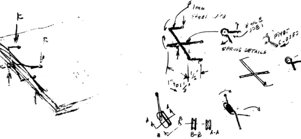
The initial design was based on a concept proposed by Professor Ernesto Blanco. Two steel "U-shaped" wires are connected at the center of their base, and this connection point also serves as a pivot point about which they each rotate. This enables each leg to stay in the same vertical plane as the corresponding leg of the other wire, and it also allows for a vertical gap distance between the right pair of legs to be the same as the distance between the left pair of legs. These wires are connected by a steel torsion spring whose natural position is in the clip's closed state, thus keeping the clip closed tightly on the paper. The ends of the legs have rubber feet/tips to provide a greater element of friction between the clip and the paper.
L3
.i4 .d' ',
SePrb@> ^-fFr I
Figure 6: Sketches by Professor Blanco of the initial concept, utilizing a torsion spring.
The design quickly evolved. In fact, one of the first design changes was also one of the largest and most important. A simple prototype of the initial design was built, and it was discovered that there were many problems. First of all, it was difficult to connect the torsion spring and the wires using the limited resources available. Although I was able to make create a prototype similar to the first design with the spot welder in the Pappalardo laboratory, it was an extremely difficult process, and it took numerous attempts. Even on its lowest setting, the spot welder was too strong and often destroyed the wire, splitting it into pieces. When the spot welder did not destroy the wire, it still severely weakened it. It became obvious that an alternate method of connecting the spring and wires would be needed to make a strong prototype. Also, it was discovered that it was extremely difficult to keep the center of rotation at the center of the two wires. The clip was very small, and the spring would have needed to be bent with smaller radii of curvature than was feasible.
i
r Io a An~,~F~~~nd:..'lr~anSC·~71· ' .r(· ~~aC,~ OR " , i" Iw' )idn't rotate bout the
orrrect point Only one side gr
paper (this side's larger than the o
N t
-Figure 7: Photo of the initial prototype with labels describing its problems.
While trying to develop a solution that would guarantee that the clip's wires would rotate properly, I developed the idea of placing the two wires on separate discs that shared an axis of rotation. This would guarantee that the wires rotated as would be necessary for operation. iI 41 .r,;a3E i XC 11 I ,, . . L -. . . .. / I- --- 1 . t, L4, ? . , , - t~ - .-ZI i
-I'
_ . 1 7.n -16 I . .:' i \t I o, I, ) ,Figure 8: Sketches showing two of the rotating disc concepts.
II
Now that the rotation problem was solved, all that remained was the problem regarding the connection of the spring. Interestingly, finding a solution to this problem became unnecessary because I decided against using a torsion spring as in the initial design.
When I reviewed the design and reevaluated the decision to use a spring, and considered all possibilities, I decided that there were better options than a spring. The project required a device that would allow movement in one direction (tightening), but not allow the parts to backtrack. I decided that a ratcheting device would provide this action better
than a spring could.
At first, I explored a linear ratchet system that would work like cable ties. The distance between the legs would be controlled by the ratchet. Once tightened, the tie/ratchet would not allow the device to backtrack. This concept had a few problems, one of them being the lack of a method of disengaging and resetting the system.
Liear
Cah
c
+cE
Ck,&a c -8 at
FL i 4 .
it s, la
t
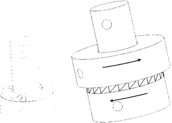
.- h't.Eventually, I decided to instead use a rotational ratcheting system. The interface between
the two rotating discs would be a series of ratcheting teeth. The shape of the teeth would only allow the discs to rotate one way (tightening the clip). To release the clip, one would just need to disengage the teeth of the ratchet. A disc spring could be used to keep the teeth engaged and the spring's force could be overcome to allow the disengagement of the teeth needed to release the clip. The final design of the ratcheting parts includes a "button" that when pressed would cause this disengagement.
h ---I !! I/-'-- r i i i · 1---r F \· · I --- i ,1 I r ____--- i c I ii \I, ; -? r L:" r r . I .I - I I i' i . '! I - ._ . _! , . I. I I ' I 'I / j I j... . - - -'
\
V
Figure 10: Rotational ratcheting design - when engaged,
the teeth only allow counter-clockwise rotation.
The final modification to the design was a modification to the legs of the clip in order to provide a firmer grip. This utilized the spring aspect of the wire of the legs. The legs
-were bent back on themselves, so that the spacing between the two sections of the legs could be compressed when the clip was tightened.
I
Hz
p·
Figure 11: Leg modification: bend allows them to act as springs to provide stronger grip.
4.3 Final Design
The final design is shown in the following sequence of pictures.
I
_ _ J II I -i I 11 -· i-.ZLZIZJA¶,
Ia ` Nd'-E
'1
f,
---
. I I .'
).,.
I
. / II..Figure 12: Views of the final design. Clockwise, starting at top left: front, right, isometric, and bottom views of the clip.
i I i ---- ,I I ; i i I
I
I:
ElC
I ., ~ ; ,.. t I C 8 ! ' ; *' *' ;/
. '-/J
4
Figure 13: Clip in its open position.
I
4J
Figure 14: Clip in its closed position, with vectors showing the forces at the surface of the paper (a compressive force from the legs and an outward reaction force for the paper).
The clip tries to loosen, however the flat faces of the teeth in that direction prevent the movement. The teeth supply a reaction force as those faces are pressed against each
other. This reaction force supplies a torque on the legs. This torque is carried down the
legs to the points where the legs make contact with the paper. This torque becomes a
compressive force from the legs into the paper. The paper also supplies a force against the legs. The paper can be modeled as a spring with a set spring constant. For the paper to apply a specific force onto the legs, therefore, it must be compressed a specific
distance (the force divided by the k of the paper). The system is in equilibrium when the component of the force that the legs apply perpendicular to the paper is equal and
opposite the force that the paper applies to the legs. This force is large enough that the paper must compress by a noticeable amount. This allows the clip to maintain a tight
5.0 Prototype
5.1 Manufacturing Process
The manufacturing process of the prototype began with the finalization of the design in SolidWorks. The two mating ratcheting parts had details that could not be machined by hand, so they needed to be created by another method. Fortunately, I was able to get access to a 3D printer, so I had the capability to manufacture them using that machine (Thanks to Professor Harry Asada and Eric Wade). Using SolidWorks, I was able to create the .stl files that the printer needed to print the parts.
Figure 15: Male and female ratcheting parts, made using a 3D printer.
Once the printed parts were finished, the next step was to create the steel wire legs. These were made by simply putting a long length of 0.0625" diameter wire into the corresponding holes in the printed parts, bending the wire using a vise, and then cutting the pieces to the desired length. Superglue was then applied to the wire, and the wire and printed parts were held firmly together while the glue set. Once the wire was fixed in place, the ends of the wire legs were inserted into short rubber feet.
Figure 16: Parts with wire legs and rubber feet added.
The mating parts were then placed together, and the disc spring and washer were placed around the hub of the male part. A wire "crank" was then inserted into the corresponding hole, engaging the teeth of the mating parts. The clip was thus completely assembled,
and the next step was to test the mechanism.
Figure 17: The male and female parts were mated, and then a disc spring, washer, and crank were added to keep the teeth engaged.
5.2 Test
Once the prototype was assembled, the next step was testing its operation. The mechanism began in its open position. It was slipped over the paper, while still open.
Figure 18: Clip in its open position, placed around a stack on papers.
Next, the mechanism was closed tightly. This can be done in two different manners. First of all, one can just press down on the two top legs. However, one can also use the crank wire. If one rotates the crank clockwise, the mechanism closes. The device is closed as tightly as possible.
Figure 19: The clip is closed by turning the crank clockwise.
Next, I grabbed the stack of papers by holding the clip and lifting off the table. I swung the papers around, and tested to make sure that the papers did not slip within the clip. I
then spent many hours simulating the types of things that could happen to the stack in an average work day, and also, clipped together several different thicknesses of stacks of paper.
Figure 20: The clip grips tightly, and the papers do not shift even when the stack is swung around.
To release the clip, I simply put my index and middle fingers on the back side of the female part, and pushed the button with my thumb, thus moving the male part relative to the female part, and also disengaging the teeth of the ratcheting faces. The paper wanted to return to its completely uncompressed state, so the parts rotated backwards a tooth or two. The clip was now set at a larger distance than was needed to hold the papers, so it could now easily slide right off of the stack.
Figure 21: The female part is held in place by the index and middle fingers while the thumb presses the button (the hub of the male piece). This disengages the teeth, and the
pieces rotate so that the clip is loose enough to slide off the papers with ease.
5.3 Evaluation (Criteria)
Now the clip needed to be evaluated using the criteria set forth at the beginning of the project.
1. The mechanism must not make any permanent damage to the paper.
The clip makes no permanent marks at all on the paper. The state of the paper after the clip is removed is the same as it was prior to the clip being attached.
2. The mechanism must work for a wide range of paper thicknesses, from only two sheets of paper to a stack "/z thick.
The clip has a very wide range of paper thicknesses that it can hold; it fulfills the preset requirement (and actually exceeds it).
3. The mechanism must be both quick and easy to both put on and remove.
The clip is slightly more difficult to put on and remove than a paperclip, but it is comparable to a binder clip. It is quicker and easier to use than the other methods discussed.
4. The mechanism must hold the paper tightly; the paper must not slip if the stack was picked up by the clip, or in any other situations that the clip might reasonably encounter in the office.
The paper did not slip relative to the clip when everyday office activities were simulated. It also did not slip even when the stack was swung around. The grip of the clip was very strong, and the rubber feet helped to prevent any slippage.
5. The mechanism must be as durable as current methods and be able to take as much force and stress without failure.
There were a few problems with this criterion. The ratcheting parts were printed out of ABS because the 3D printer was the only plausible option available for the prototype. The ABS is not exceptionally strong, and during testing, a torque placed on the hub by the crank created a crack in the hub, and the part had to be repaired (a simple process using PVC cement). Although this break occurred when more force than was necessary was applied to the crank, it would be a good idea to make future prototypes out of a
6.0 Conclusions & Suggested Improvements
As shown in the previous section, the project was a success. The design fulfilled the criteria established at the beginning of the project. And the prototype proved the concept that was proposed. However, there is further work that could be done. If I were to continue and pursue making a market quality clip that was durable and fully operational, I would make the following improvements to the design.
First of all, in striving to build the prototype in a limited amount of time, I was very conservative with some design decisions. Wall thicknesses in the ratcheting parts were made extremely large. In fact, overall, the pieces are much larger than is necessary. Also, if there were other methods of production available, the clip could be made out of much fewer pieces, possibly as few as four. I would also use a much stronger material than ABS (which was used because it was the only feasible option with the limited time and resources that I had). All in all, the prototype is much larger and more complex than the final product would need to be. It is bulky and not the most aesthetically pleasing
clip.
Finally, I would optimize a few aspects of the clip. With better production methods, there could possibly be more teeth in the next generation, which could allow the clip to hold the paper with a more constant force as the thicknesses vary. Also, the slope and height of the teeth, along with the disc spring, could be optimized to make it require less force to close the clip, while still maintaining enough force from the spring, so that the teeth stay engaged unless purposely disengaged. Other aspects of the clip could be
optimized with regards to human factors. Because it would be used in office situations, it is important that its ease of use for the consumer is improved.
Finally, the design should eventually be modified with the manufacturing process in mind. The process would change significantly if I wanted to make many of the clips, as opposed to just one or two prototypes. As an office product, the clip would need to be able to be mass-produced, and the design would need to reflect that.
This project showed promising results for applications related to office paper attachment. However, an unexpected benefit was the potential use of the ratcheting concept in other applications. The most promising of these applications is a clamp that could be used in machining and other tool related areas. The final recommendation is that this area be pursued further.