DEVELOPMENT CYCLE TIME REDUCTION FOR CUSTOMIZED HELICOPTER WIRING SYSTEMS
by
SCOTT D. HOWARTH B.S., Civil Engineering
United States Military Academy, 1991
Submitted to the Department of Civil and Environmental Engineering and to the Alfred P. Sloan School of Management in partial
fulfillment of the requirements for the Degrees of Master of Science in Civil and Environmental Engineering
and
Master of Science in Management
in conjunction with the Leaders for Manufacturing Program at the
Massachusetts Institute of Technology June, 1997
@ Massachusetts Institute of Technology (1997). All Rights Reserved.
Signature of Author
Department of Civil and Environmental Engineering Sloan School of Management
May 9, 1997
Certified by .
Charles H. Helliwell, Jr., Senior iicturer Department of Civil and Environmental Engineering, Thesis Advisor Certified by
Lawrence M. Wein, Professor of Management
Sloan School of Management-hesis Advisor Accepted byJoseph M. Sussman Chairman, Departmental Committ4 gn Graduad Sjidies Accepted by
-.
0;i..
.!.
a`
.•
•.
1 1
Jeffrey A. Barks
Associate Dean, Sloan Master's add Bachelor's Programs
DEVELOPMENT CYCLE TIME REDUCTION FOR CUSTOMIZED HELICOPTER WIRING SYSTEMS
by
SCOTT D. HOWARTH
Submitted to the Department of Civil and Environmental Engineering and the Alfred P. Sloan School of Management on May 9, 1997 in partial fulfillment
of the requirements for the degrees of
Master of Science in Civil and Environmental Engineering and Master of Science in Management
ABSTRACT
Changes in the competitive environment of the helicopter industry have forced helicopter manufacturers to respond to increasing global competition and increasing rates of innovation to meet customers' needs. In many of these organizations, senior managers have directed their development organizations to reduce development cycle time and cost
by more than 30%. Establishing and implementing this change effort requires a problem
solving methodology that is tailored to the unique needs of development organizations. This thesis proposes a methodology to address the problem of development cycle time reduction. The methodology is presented in a general format to ensure its
applicability to a wide range of industries, and is based on the following three concepts:
1. A systems view of the "Rework Cycle" provides valuable insight as to where
to focus improvement efforts.
2. A queuing network model is an effective tool to analyze the current
development process and to explore potential changes.
3. The cycle time reduction effort should concurrently investigate both
incremental and radical changes through the use of cross-functional teams. As an application of the proposed methodology, this thesis chronicles a major American helicopter manufacturer's efforts to confront the challenges of reducing
development time for derivative helicopters. Specifically, this thesis focuses on a critical element of the helicopter development process: the design and fabrication of electrical and avionics wiring harnesses.
The company's efforts to reduce development cycle time are described in detail as well as further improvement recommendations. One recommendation calls for the establishment of design-planning teams as a means of achieving improved process performance. Many of the proposed changes will depend on management's ability to lead a large-scale, difficult change effort in both the technological and social systems within the organization.
Thesis supervisors
Charles H. Helliwell, Jr., Department of Civil and Environmental Engineering Prof. Lawrence M. Wein, Sloan School of Management
Acknowledgments
First, I wish to thank my wife Kristen for her support and love during the past two years.
I would also like to thank Charlie Helliwell and Larry Wein, my advisors at MIT. They helped shape the ideas contained in this thesis and provided me unfailing support for the duration of this research effort.
At Sikorsky, I owe my deepest thanks to Ray Fahringer for providing the friendship, leadership, and guidance which made my short stay at Sikorsky so
worthwhile. I would also like to acknowledge everyone within the DMC and DMC II who accepted me as one of their own from the very start. The top-level support of Jack Fischer and John Carpino was also greatly appreciated.
The past two years have been most valuable because of the outstanding
individuals I have had the opportunity to meet in the Leaders for Manufacturing Program. My thanks to all of my classmates, but especially: to Liana, John, Dan, Melanie, Pat, and Will, my closest friends and from whom I have learned the most during the past two years.
Finally, I gratefully acknowledge the support and resources made available to me through the Leaders for Manufacturing Program.
Table of Contents
1. Introduction 11
1.1. Statement of the problem 11
1.2. Goal of the research project and focusing assumptions 12
1.3. Thesis background 13
1.4. Thesis layout 14
2. Methodology for product development cycle time reduction 17
2.1. Develop a "systems view" of the working environment 18
2.1.1. The traditional development project view 20
2.1.2. View of development project which recognizes quality and rework 20 2.1.3. View of development project which recognizes undiscovered rework 21
2.2. Target areas for improvement 23
2.3. Pursue both incremental and radical improvement 23
2.3.1. Cycle time reduction tools 24
2.3.2. Pursuit of incremental change 26
2.3.3. Pursuit of radical change 27
2.4. Integrate findings, implement change, and refine 27
3. Cycle time reduction of the S70 helicopter 29
3.1. Cycle time reduction at Sikorsky 29
3.2. S70 Wiring harness development 32
3.2.1. Wiring Harness Process 32
3.2.2. Organizational structure 34
3.2.2.1. DMC II organizational structure 34
3.2.2.2. Wiring harness organization structure 37
3.3. Cycle time reduction of wiring harness development 38
4. Cycle time reduction methodology applied to S70 wiring harness development 41
4.1. Develop systems view of harness development process 41 4.2. Target areas to improve harness development cycle time 43 4.2.1. The impact that "manpower" has on harness development 43 4.2.2. Improving "productivity" in harness development 44
4.2.2.1. Rewards and incentives 45
4.2.2.2. Feedback and performance appraisal 46
4.2.2.3. Overtime 47
4.2.2.4. Overlapping job responsibilities and cross-training 48
4.2.2.5. Co-location and coordination mechanisms 49
4.2.2.6. Meetings 49
4.2.2.7. Informal communications 50
4.2.2.8. Information systems 51
4.2.3. Improving "quality" in harness development 51
4.2.3.1. Rule based technologies and 3-D modeling 52
4.2.4. Factors that will facilitate "rework discovery" in harness development 53
4.3. Pursuit of incremental and radical improvement in the harness development process55
4.3.1. Traditional cycle time measurement tools 55
4.3.2. Queuing network model of wiring harness development 59
4.3.3. Queuing network simulation tool 61
4.3.3.1. Purpose of simulation 61
4.3.3.2. Simulation details 63
4.3.3.3. Simulation input and output 67
4.3.4. Current model simulation results 68
4.4. Integrate findings, implement change and refine harness development 71
5. Incremental and radical process improvements 73
5.1. Efforts to achieve cycle time reduction through process improvements 73
5.1.1. Incremental process improvements 75
5.1.1.1. Documenting the existing process 75
5.1.1.2. Breakdown problem 75
5.1.1.3. Brainstorm changes 76
5.1.1.4. Integrate and develop incremental preferred process 76
5.1.2. Radical process improvements 77
5.1.2.1. Design-planning teams 78
5.1.2.2. Cross-training 78
5.1.2.3. Design philosophy 79
5.1.2.4. 3-D modeling 80
5.2. Integration of incremental and radical process improvements 80
6. Implementation plan for Design-Planning Teams 81
6.1. Elements of the Design-Planning team structure 81
6.1.1. Charter 81
6.1.2. Team composition 82
6.1.3. Team roles 83
6.1.4. Harness development management: Standardization and improvement 83 6.2. Final proposal for harness development organizational structure 84
7. Organizational barriers to implementing Design-Planning Teams 87
7.1. Formal organizational barriers 88
7.2. Political barriers 88
7.2.1. Organizational politics 88
7.2.2. Career progression 89
7.2.3. Layoffs 90
7.3. Cultural barriers 90
7.3.1. Complacency bred by military helicopter industry 91
7.3.2. Emphasis on schedule 92
7.3.3. Defense driven compliance issues 92
7.4. Typical problems that teams encounter 92
8. The DMC H process and its applicability to the construction industry. 95
8.1. Concurrent engineering principles 95
8.3. Rewarding team performance and providing constructive feedback 98
8.4. Changing the physical layout 99
8.5. Redesigning work procedures 99
8.6. Cultivating a sense of collective responsibility 99
List of Figures
Figure 2-1: General development cycle time reduction methodology. 17 Figure 2-2: Traditional view of development projects. 20 Figure 2-3.: Traditional view with factors affecting work being accomplished. 20 Figure 2-4: Development project view which includes the "Rework Cycle. " 21 Figure 2-5: Development project view which includes undiscovered rework. 22 Figure 3-1: Configuration for two development programs. 31 Figure 3-3: Development Manufacturing Center II Organizational Chart 36 Figure 4-1: "Rework Cycle" applied to harness development process. 41 Figure 4-2: Communication frequency versus separation distance. 51 Figure 4-3: Percent of work actually complete vs. Percent of work perceived complete with low
quality and long rework discovery. 54
Figure 4-4: Process flow diagram of harness development process. 59
Figure 4-5: Queuing harness development network 60
Figure 4-6: Completion ofjobs for a single customer. 69 Figure 4-7: Backlog of hours per person per work station. 70 Figure 4-8: Average queue times and touch times of each job type as a percentage of the total
time in the system. 70
Figure 6-1: Harness Design-Planning organizational structure. 84 Figure 8-1: Cost of change profile for large projects. 96 Figure 8-2: The effect of concurrent activities on overall project cost. 97
1.
Introduction
This thesis proposes a methodology to aid project managers in reducing product development cycle time. In Section 1, a framework for the entire thesis will be provided, beginning with a statement of the problem and justification for research into development cycle time reduction. This section will detail the objectives of the research and provide a road map for the presentation of the arguments and ideas stated within this thesis. This section concludes with an overview of the remaining chapters.
1.1.
Statement of the problem
Many companies have realized that competing on time is becoming as important as competing on quality or cost. Companies can no longer dictate the lead time of their products, but must deliver them when their customers want them. Customers are also demanding that products be tailored to meet their specific needs, a requirement which is forcing companies to confront challenges such as customization. Increasing global competition and a growing rate of technological innovation have also increased the demand for new features, which has created even shorter product life cycles. For these reasons, reducing product development cycle time has become a primary focus for improvement efforts in many companies.
The product development process is often on the critical path in the realization of new products. Moreover, with the increasing need for customization of existing products, the development process is also becoming a large part of lead time of what were once standardized products. Unfortunately, however, development processes that focus on customization have unique characteristics which defy the use of traditional continuous improvement tools to reduce cycle time. Most development projects are dynamic and iterative, ranging from months to even years. By their very nature, their end results are unique, therefore the development process is never exactly replicated. As such, many of the tools and techniques presented in continuous improvement methodologies are not applicable to mass customization. Furthermore, customization requires very different
organizational structures, values, management roles and systems, learning methods, and ways of relating to customers.' Invariably, customized products require the contribution of many people whose skills span different functional disciplines---disciplines which are
often strongly tied to ever changing technologies. Typically, these functions do not interact or come together in the same sequence every time. At times, the success of a product development process can also depend on the creativity of its members. While there is often some amount of repeatable tasks, successful product development will
always require a significant degree of innovation. For these reasons, product development is an ambiguous process, hard to define and even harder to improve.
Even faced with these challenges, the upper management of many companies are setting aggressive improvement goals for their development organizations, directing them to reduce development cycle time by 30% or more. These ambitious cycle time goals, coupled with the difficulties of improving a large and complex development process, requires a focused and well planned effort that integrates the contributions of many people throughout the company. In addition, creating and guiding such a cycle time reduction effort to an effective solution and a successful implementation requires a problem solving methodology that is tailored to the unique needs of this type of problem.
1.2.
Goal of the research project and focusing assumptions
This thesis presents a methodology which addresses the specific problem of product development cycle time. The methodology is based on three key concepts. The
first concept is that a systems dynamics model of the rework-cycle provides invaluable intuition as to where to focus development cycle time reduction efforts for complex development projects.
The second concept is that a quantitative model of the current development process provides a critical tool in a cycle time reduction effort. Specifically, a queuing network model is appropriate for this type of problem because it demonstrates the
I Andrew C. Boynton and Joseph Pine II, "Making Mass Customization Work," Harvard Business Review, September-October (1993): 108-119.
significant effects of many tasks vying for the attention of limited engineering and technical resources.
The third concept described in the methodology is that development cycle time reduction efforts should concurrently investigate both incremental and radical changes. This thesis argues that the path leading to incremental change differs considerably from the path leading to radical change. There are benefits to conducting two separate efforts to explore both paths. In addition, the end result, which can combine both types of change, may prove to be the optimal solution.
1.3.
Thesis background
This thesis is based on a seven month internship sponsored by United Technologies Corporation's Sikorsky Aircraft in conjunction with the Leaders for Manufacturing program at MIT. Sikorsky Aircraft Corporation is aggressively pursuing cycle time reduction in an effort to increase sales of its S70 helicopter. At one time, the helicopter industry was somewhat immune to the pressures of cycle time reduction, mass customization, and shorter lead times. Today, however, with military spending on new rotorcraft on a seemingly irreversible downward slide, helicopter manufacturers are tailoring their operations to be more responsive to customers' needs.2 This thesis
describes and contributes to the cycle time reduction effort in Sikorsky's Developmental Manufacturing Center II (DMC II), which is responsible for the design and delivery of new and customized S70 helicopters.
The task of designing and building a new or derivative aircraft presents a massive undertaking; therefore, this thesis focuses on a single key element, the development process of the wiring harness assemblies.
The cycle time reduction project at Sikorsky provides a detailed case study of the application of both radical and incremental reduction efforts. Prior to the start of this study, Sikorsky had already made radical process and structural changes. The process changes transformed a sequential development process into a more parallel and
2 Robert Ropelewski, "The Helicopter Industry: About to implode?," Aerospace America, April (1996): 38-43.
concurrent process whereby manufacturing engineering could start their planning based on preliminary data released by the design engineers. The structural changes created a new department, the DMC II-a cross-functional team headed by one manager with the authority to allocate resources over a wide range of development projects.
My primary role within the cycle time reduction effort was to study the harness development process, examine the effectiveness of their radical changes to date, and recommend and implement additional changes that would further reduce development cycle time and cost. Consequently, it provided me with an excellent opportunity to formulate and apply a general cycle time reduction methodology that could be used in a variety of different industries.
This thesis has three goals. The first goal is to describe a general methodology to attack the problem of reducing product development cycle time. The second goal is to use the project at Sikorsky as a case study to examine the effectiveness of the proposed methodology. The third goal is to discuss the lessons learned with respect to Sikorsky's use of cross-functional teams to reduce product development cycle time, and how these lessons might apply to large-scale design and construction processes.
1.4.
Thesis layout
The thesis is organized into eight chapters to address the three goals listed above. Chapter 2 addresses the first goal by describing a general methodology to reduce product development cycle time. Chapters 3-6 address the second goal by detailing the cycle time reduction effort within Sikorsky. The final two chapters address the third goal with a discussion of the lessons learned from Sikorsky's use of cross-functional teams and how these lessons apply to the construction industry.
* Chapter 2 describes the methodology in general terms. The methodology is based on a "systems view" of the rework cycle and argues the benefits of concurrently pursuing both incremental and radical change. In addition, this methodology can be used as a guide for similar product development cycle time reduction projects.
* Chapter 3 describes the cycle time reduction effort in Sikorsky's Development Manufacturing Center II. It also details the electrical wiring development process and the organization that was in place at the time of the study.
* Chapter 4 applies the cycle time reduction methodology presented in Chapter 2
to the harness development process in the DMC II. It also describes a queuing network model that was used in the pursuit of further incremental improvement. The benefits of this model over existing tools such as Gantt charts, Critical Path Methods, and Pert diagrams are outlined.
* Chapter 5 describes in more detail the approaches that were taken at Sikorsky in pursuit of further incremental and radical process improvement. It also describes a final integrated solution to the harness cycle-time reduction problem-the implementation of design-planning teams.
* Chapter 6 details the implementation plan for design-planning teams to further reduce harness development cycle time. Tradeoffs between design-planning teams and functional teams are discussed, and a final harness development organizational structure is proposed.
* Chapter 7 focuses on the organizational issues surrounding implementing
process improvement in the "team" environment existing within the DMC II. It will also discuss the challenges associated with using teams in a downsizing environment.
* Chapter 8 describes the lessons learned from the project at Sikorsky and how these might apply to the construction industry. It will focus on the similarities between large-scale customized helicopter development and the
2.
Methodology for product development cycle time
reduction
Companies have identified that time to market is a key competitive advantage and have set ambitious goals to reduce the cycle time of their product development processes. The first step towards attaining these goals is to define and implement an appropriate methodology for the development cycle time reduction problem. A methodology that will take a company from an urgent need to reduce cycle time, to a definitive strategy that has a realistic chance of achieving improvement targets. This thesis argues that the most efficient way to reach this point depends on the organization's ability to identify the "systemic forces" influencing their working environment, quickly investigate a wide range of options, and then establish consensus on a vision for the future.
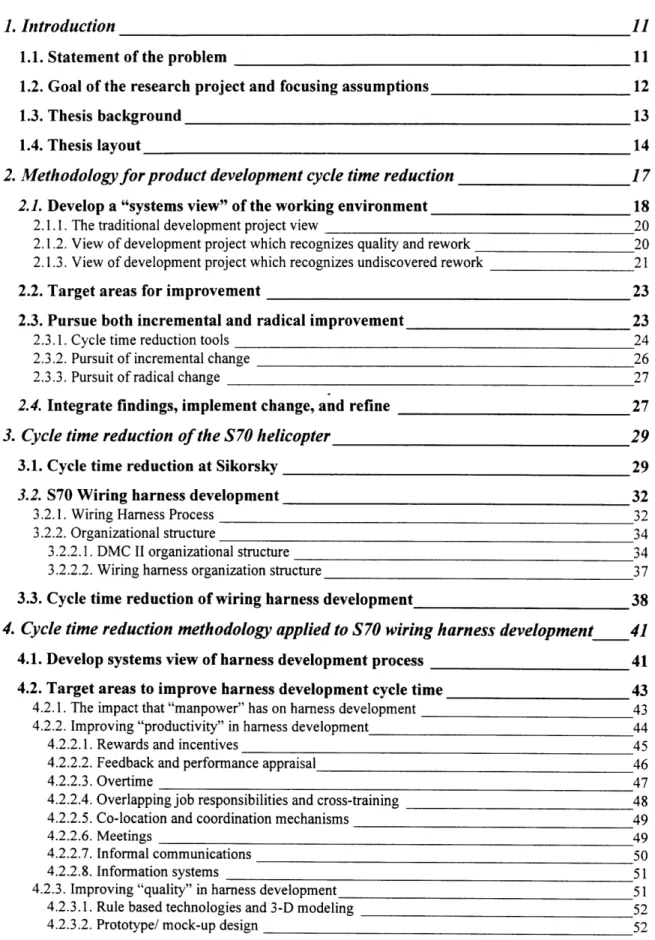
In this chapter, general elements of a development cycle time reduction
methodology are outlined in detail (Figure 2-1). Chapter 4 will apply this methodology to the harness development cycle time reduction project at Sikorsky. The elements of the methodology are described in general terms to ensure their applicability to a wide range of product development projects beyond the helicopter industry.
2.1.
Develop a "systems view" of the working environment
Before the start of any cycle time reduction effort, it is imperative that all players have a clear understanding of the system within which they work. This ensures that limited company resources such as time, people, and money are targeted for the right project and also at the right areas or "pressure points" within that project. The field of "systems thinking" provides a valuable framework that aids managers in ensuring well targeted improvement efforts. In The Fifth Discipline, Peter Senge writes that "by
developing the capability to see the forest and the trees, companies will be in a position to respond powerfully to the challenge of complexity and change."' This thesis argues that the first step that should be taken in any cycle time reduction effort should be the
formulation of a "systems view" of the development environment. Senge also argues that mastering the language of systems thinking first requires knowledge of other
important disciplines such as personal mastery, mental models, shared vision, and team learning. These disciplines combine together to create what he refers to as the "learning organization." As Figure 2-1 suggests, the inherent dynamic nature of a "systems view" will require a flexible, working model, continually updated and validated to reflect inevitable changes.
Since the 1980s, the field of System Dynamics has proven significant to understanding the complex nature of development projects. The concept of the "Rework Cycle" is well described in the work of Kenneth G. Cooper, where he has used its basic structure to model numerous software, construction, electronic systems, and aerospace development projects. The robust nature of the rework cycle makes it particularly applicable to the development environment within Sikorsky's Development
Manufacturing Center II. A thorough understanding of the "Rework Cycle" as described by Cooper is essential in the creation of a "systems view" of the development
environment--the first element of the development cycle time reduction methodology proposed by this thesis.
3 Peter M. Senge, The Fifth Discipline: The Art and Practice of the Learning Organization (New York: Doubleday, 1990): 310.
Even with all of the recent advances in project management systems and tools, managers of large projects continue to get surprised by rework which can result in cost overruns, late deliveries, scarce resources and contract disputes. Unfortunately,
conventional project management methods such as the Critical Path Method (CPM) and Gantt charts treat a project as being composed of a set of individual, discrete tasks. Each task is portrayed as having a definable beginning and end, with the work content either "work to be accomplished," "work being accomplished," or "work accomplished." Little account is taken of the quality of the work completed, the release of incomplete or
imperfect sub-tasks, or the amount of rework which will be required. These conventional methods are particularly inappropriate for development projects, in which there is a naturally iterative process of design, engineering, and manufacturing. More experienced managers understand the impact of rework and typically build "slack time" into their schedules to account for it. Still, however, the accuracy of these schedules depend on the experience, expertise, and sometimes luck of the individual managers and rarely reflect the actual cycle time of the project.
A model that recognizes rework, plans for it, monitors it, and helps managers reduce its magnitude and duration can be of great value to development organizations. The "Rework Cycle" model "reflects a more strategic view of projects, and accounts for the quality of work done and the causes of productivity variations."4 Unlike traditional methods, it creates a clearer picture of the effects that management actions can have on staff productivity and the quantity of rework-and how the consequences spread through an entire project. The framework is quite dissimilar to CPM/PERT models; "it treats a project not merely as a sum of a sequence of discrete tasks, but as flows of work in which there are multiple rework cycles."' The following paragraphs will describe the
underlying structure of Cooper's "Rework Cycle" in detail.
4 Kenneth G. Cooper, "The Rework Cycle: Why Projects are Mismanaged," PMNETwork, February 1993.
2.1.1. The traditional development project view
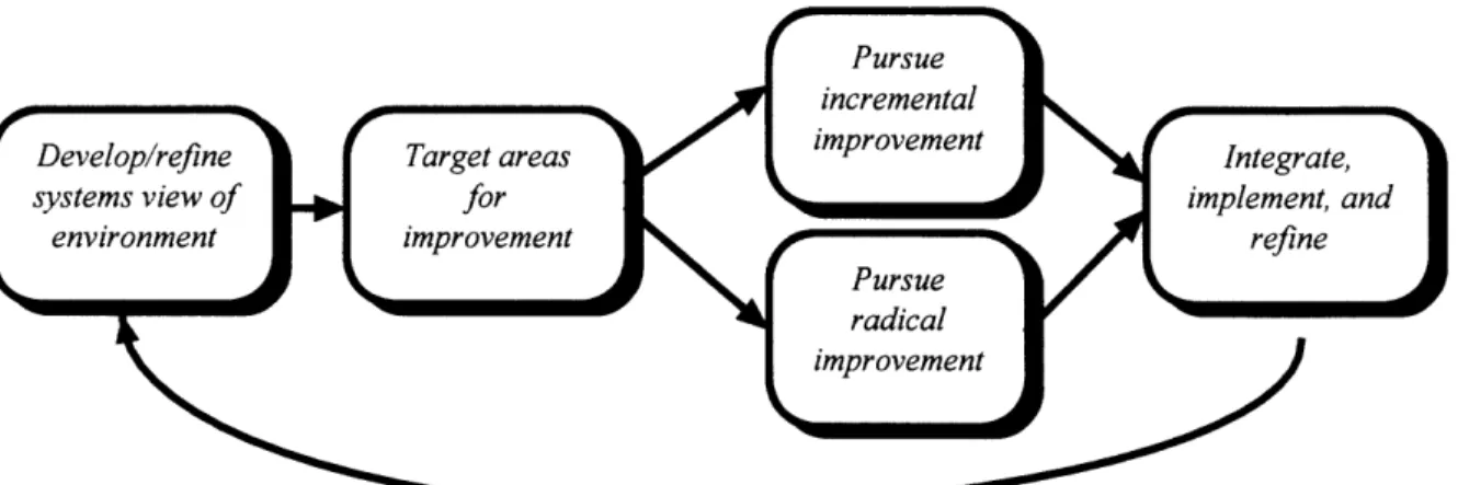
Typically, development projects are tracked based on work to be accomplished,
work being accomplished, or work accomplished. The first step in creating a more
realistic view of development projects is to model the process as a more continuous
stream of work as shown below:
Figure 2-2: Traditional view of development projects.
At the start of a project, all work resides in the pool of work to be
accomplished. As these tasks are drained over time, they flow through work being accomplished, such that at the end of the project all the tasks fill the stock of work accomplished. This model can be taken a step further by recognizing that as a project
progresses, changing levels of manpower working at varying levels of productivity ultimately determines the pace of work being accomplished.
Manpower Productivity
Figure 2-3: Traditional view with factors affecting work being accomplished.
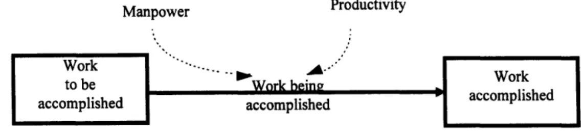
2.1.2. View of development project which recognizes quality and rework
A more accurate view of development projects recognizes the existence of rework cycles. Below, what Cooper terms the quality of work executed should be
thought of as a "valve" controlling the portion of the work flow being accomplished that will or will not require rework.
Manpower Productivity Quality
Figure 2-4: Development project view which includes the "Rework Cycle. "
Unlike other program analysis tools and systems, the rework cycle recognizes the real-world phenomenon that work is "executed" at varying quality levels. Potentially ranging from 0 to 1, the valve of quality depends on many variable conditions in the project and company. The fractional value of quality determines the portion of the work
being accomplished that will enter the pool of work actually accomplished, which will
never again need re-doing.
The distinction between productivity and quality is important. People may exhibit high productivity, but be putting out work of low quality that requires later re-working. In this condition, the net throughput to the pool of work actually accomplished is low.
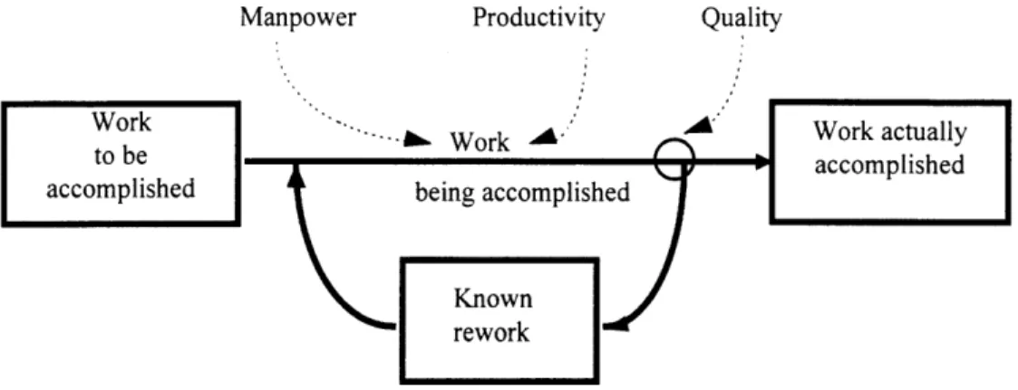
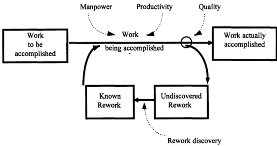
2.1.3. View of development project which recognizes undiscovered rework
In reality there is a critical "buffer" in which rework lingers until it is
identified as needing rework. Cooper has termed this buffer undiscovered rework, which consists of "those tasks or work products that contain as-yet-undetected errors of
commission or omissions, and are therefore perceived, and reported by all traditional
systems, as being done."6 The errors are usually detected by downstream efforts or testing. This rework discovery may occur months or even years later, during which time dependent work has incorporated these errors. The more tightly-coupled and parallel the project tasks are, the greater the effect on subsequent rework cycles will be.
Once discovered, the known rework demands the application of resources, beyond those needed for executing the original work. Executed rework enters the flow of
work being accomplished, subject to similar productivity and quality variations. Even
some of the re-worked items may then flow through the rework cycle one or more subsequent times.
Manpower Productivity Quality
Rework discovery
Figure 2-5: Development project view which includes undiscovered rework. 7
For project management success, it is imperative that undiscovered rework be acknowledged, aggressively sought out, and prevented as much as possible. Cooper argues that all development plans and schedules should be set accordingly so as to reduce the disruption of the surprise of undiscovered rework. Furthermore, a culture should be
cultivated in which early discovery of rework is encouraged.
6 Ibid.
7 Structure adapted from "The Rework Cycle: Benchmarks for the Project Manager," Proiect Management Journal, March, 1993.
2.2.
Target areas for improvement
Having developed a "systems view" of the development environment, managers, process owners, or teams can now specifically target areas for improvement. As
identified in Cooper's view of the "Rework Cycle" these areas or "pressure points" include manpower, productivity, quality, and rework discovery. The challenge of successful project management and development cycle time improvements focuses on maintaining an optimal balance among these four variables. Often, improvements in one area can lead to increased problems in others. Chapter 4 will discuss the tradeoffs of these variables and how they apply to the harness development process at Sikorsky.
2.3.
Pursue both incremental and radical improvement
Now that team members share a common view of the system within which they work, and specific "high payoff' areas have been targeted for improvement, the quest for reduced cycle time can follow two fundamentally different paths, 1) exploring many incremental changes to the current development process, or 2) searching for a radical redefinition of the development process by changing some or all of its basic structural elements. The premise made in this thesis is that although both of these paths will likely lead to quite different solutions, sound reasons exist for investigating both paths
concurrently. The primary reason is that at the start of the investigation there is no way to guarantee that the current development process will be able to achieve the desired goals. This assumption stems from the concept that an infrastructure underlies the current process. Hayes, Wheelwright and Clark propose a definition for infrastructure: it is composed of the systems, practices and policies that drive an organization's behavior.8 Whereas Hayes et al. present a list of infrastructure elements within a manufacturing organization, that list can be modified slightly to fit a product development environment by including the following elements:
1. Human resource policies and practices, including management selection and training.
8 Hayes, Robert H., Wheelwright, Steven C. and Clark, Kim B., Dynamic Manufacturing: Creating the Learning Organization (New York: The Free Press, 1988) 362.
2. Quality assurance and control systems.
3. Work scheduling and document control systems. 4. Performance measurement and reward systems.
5. Organization structure and design.
Incremental change will modify the process itself but.may not get to the root of the organization--the infrastructure elements. If the infrastructure has an inherent limit or creates a sufficient drag on the performance of the organization, then achieving the cycle time target without impacting these elements may prove too costly or inefficient.
The best possible chance of meeting cycle time goals requires concurrently investigating incremental and radical process improvements. If only a single path is followed, it could result in a proposed solution that is insufficient to meet the cycle time goals, and the exercise must begin again. More likely, there will be no accurate way to judge the true merit of the proposed solution. The exercise may generate enough
momentum behind the proposal and the organization will expend a significant amount of effort implementing a poor solution. Thus, the rationale behind this step in the
methodology is to reduce the risk of implementing an inefficient or inadequate solution.
2.3.1. Cycle time reduction tools
Although the radical and incremental improvement paths fundamentally differ, they both address the issue of cycle time within the same organization that designs and manufactures the same product. Therefore, both investigations can share a number of common tools and resources. Both paths include the following:
Cross-functional teams: The most important element of cycle time reduction
consists of the members of the process improvement team. In the case in which the development process extends beyond a single function, the cycle time reduction team
must be staffed with people from the affected functions. A cross-functional team proves crucial for two reasons. First, only by involving experts from each function will the team develop a true understanding of the current process and the potential alternative. Second, this methodology aims not only to find the most appropriate solution, but also to create the momentum and support within the organization to implement change as quickly as
possible. The most effective way to build this support within the groups and
organizations that will ultimately be impacted, is to use the team members as the core change agents. For both of these reasons, the team members must have not only intimate knowledge of the development process, but also the respect and leverage within the organization to effect change.
Detailed definition of the current process: The team should start the study by
developing a shared understanding of the current process and the detailed steps in each functional area. This is a crucial exercise because within a multi-function development process it is very likely that each team member will initially come to the meetings focused solely on the needs of his or her function. Both paths to a solution involve negotiation and compromise between functions, which requires that all team members must first develop an understanding of each other's needs, the functional design
processes, and the interfaces and dependencies between functions. Even more important is the development of mutual respect between the team members and the shared belief that all functional groups provide valuable contributions to the process.
Analytical model of the design tasks: A complex development process will often
span many months and touch numerous individuals. Amid all of this detail, it is essential to develop a broad and basic model of the product development process. Ideally, this model should be as simple as possible yet still describe all of the essential elements. These elements include the basic development tasks, the resources applied to these tasks, and the dependence, order, and sizes of the different development tasks. Finally, because the goal of the exercise is to address cycle time, the analytical model must capture the effects of these elements on the total cycle time of the development project.
The analytical model has two primary purposes: communication and evaluation. In order for individuals to operate effectively in this type of team, they must develop a common understanding of the entire scope of the development process. The complexity and specialized detail of each individual function acts as a barrier to fostering effective cross-functional discussion. In addition, the combined complexity of all the functions makes it difficult to discuss the development process as a whole. The task of developing a relatively simple model of the process provides an effective mechanism with which to
identify the key elements of the process. In addition, any large scale changes will require the approval of people outside the study team, most often upper managers, who have very little knowledge of the entire development process. Defining a simple, yet robust, model which defines the development is an effective way to communicate the current process and the proposed changes. Effective communication to people outside the team is the key to first getting approval for implementing the changes and then spreading the vision of the future to the people who must enact the change.
Finally, there will be many conflicting suggestions and opinions about the effects of potential changes and strategies. An analytical model serves as a tool that can judge the potential gains and costs of the changes. This analysis is often crucial in order to achieve consensus within the process improvement team. In addition, some amount of analysis is required for obtaining upper management buy-in, particularly when the proposed changes are broad and affect a number of organizations.
Before the exercise can proceed to the next stage, the cross-functional teams, the definition of the current process, and the analytical model must be sufficiently refined.
Such refinement can be achieved when a cross-functional team 1) has been chartered and is functioning effectively; 2) has documented in detail the current process; and 3) has achieved consensus on an analytical model. The next stage will start by dividing the effort and the people into two sub-teams, each pursuing either an incremental or radical path.
2.3.2. Pursuit of incremental change
The primary purpose of this path is to examine the process at a detailed level, then generate many proposals for separate changes to the process, and, finally, integrate the most effective changes into a single, faster process with fewer rework iterations. This new process must be developed in sufficient detail so that team members can describe it to people outside the team, because those people will be expected to quickly implement the changes in their daily activities.
2.3.3. Pursuit of radical change
The purpose of this path is to discover and evaluate new ideas that will change the fundamental infrastructure of the development process. A single sub-team is formed to travel this path. This team begins with a broad understanding of the development process, which was gained by creating the analytical model of the current process.
Through reengineering efforts, the team attempts to define a more efficient, faster development process.
2.4. Integrate findings, implement change, and refine
Having developed two complete proposals for change, the next step requires integrating both sets of ideas into a single implementation plan. It is important in this step not to lose sight of the "systemic view" of the development environment that was discussed earlier. This may prove as simple as accepting both proposals and laying out
all of the tasks needed to implement both sets of changes. More likely, though, the integration process will involve negotiation and compromise on both proposals. This integrated solution can then be implemented throughout the organization if the required amount of momentum, acceptance, commitment and responsibility are achieved.
In order to transition this exercise from the investigation of the cycle time reduction problem, to a successful implementation of change, this final integration of
ideas must also accomplish the following goals:
1. Gain acceptance at all levels of the organization. 2. Gather momentum for implementing change.
3. Gain commitment of upper management to support the change.
4. Create change agents who accept personal responsibility for making the change happen.
These goals, in fact, underlie every step in the methodology, and many of the earlier activities have laid the ground work for a transition from studying the problem to implementing a solution. Therefore, even while engaging in the generation of new concepts, the team members must think ahead to the time when some of their ideas will be implemented and how these changes will influence the overall development system,
specifically, the "Rework Cycle." This means that throughout the exercise, the sub-teams should be integrating their ideas, presenting them to upper management and the rest of the organization, and imagining what role each team member will play in the
implementation. It is crucial that the team members believe that this exercise serves not simply as a study, but rather as the first step towards implementing change.
3.
Cycle time reduction of the S70 helicopter
In order to set the stage for the analysis in the following chapters, this chapter will outline the motivation for cycle time reduction at Sikorsky Aircraft and then describe the current wiring harness development process and organization.
Examining cycle time reduction of the S70 helicopter provides a unique
opportunity to study a construction project that is carried out on a scale that dwarfs many conventional commercial products. Like most complex, large-scale projects, the S70 development process can be broken into distinct sub-processes, each of which offers a sufficiently large scope to examine the issues of product development. One of these sub-processes, the electrical and avionics wiring development, is the basis of the data for this thesis.
This thesis focuses solely on the sustaining product development process, and does not include the original design work that created the first S70 aircraft. It simply encompasses the development activity expended to customize an S70 for a new customer. It still, however, is a large scale design and manufacturing effort that will be repeated numerous times--hopefully for several decades to come. In addition, each iteration is very similar in types of activities and amount of labor. As a repeatable activity, the S70 harness development process provides a perfect opportunity to analyze a relatively stable development process and then propose changes that can be applied and refined over a number of future projects.
3.1.
Cycle time reduction at Sikorsky
At a 1995 UTC Executive Conference in Hartford CT, the President and CEO of
United Technologies, George David, emphasized the importance of continuousimprovement within UTC, and expressed his fanaticism with the kaizen process. He stated that "kaizen proves to our employees, and to all of us, the leverage of breakthrough thinking. Kaizen blows up barriers, questions the unquestionable, and slaughters sacred cows." At the time of this project, Sikorsky had embraced the kaizen process and had
established an Agile Manufacturing Department responsible for training and implementing kaizen principles.
In Sikorsky's pre-kaizen training course, the Agile Manufacturing Department clearly highlights the challenges that Sikorsky is facing in the helicopter market. With reduction in U.S. military purchases and cost plus pricing, Sikorsky is focused on
reducing costs to ensure its success in the price-sensitive commercial market. Benchmark information, supplied by the Agile Manufacturing Department, indicated that competitor products typically cost 30% less to produce in 40% less time. Consequently, in order to remain competitive in an increasingly tight market, Sikorsky Aircraft identified cycle time and cost reduction as measurable goals to increase sales of S70 aircraft. To confront this challenge, Sikorsky created a new department, the Development Manufacturing
Center II, which was chartered to "provide tailored-to-contract processes based on concurrent design principles that could flexibly develop alternate helicopter configurations to satisfy customer requirements." More specifically, the DMC II's mission was to "perform design, systems integration, test, manufacturing, and
installations of low quantity modifications, inclusive of proof-of-principle, prototype, and development programs, drawing upon the technical skills of Sikorsky Aircraft using tailored processes which yield high quality products at a competitive cost."
Faced with fewer U.S. military purchases and tighter program budgets, the DMC II was challenged to take 30% out of the cost of producing derivative and modified
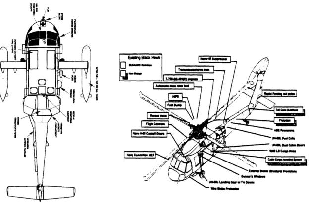
helicopters; a remarkable challenge, considering the significant amount of design activity, performed by every engineering discipline, that was needed for each new customer to incorporate unique combinations of standard and non-standard options. For instance the
choice of configuration, depicted in Figure 3-1, is carefully tailored to match each customer's specific requirements.
9 EI a
p B
Figure 3-1:. Configuration for two development programs.
This design effort, while small relative to the initial development, is a complex task that involves numerous engineers and technicians and can require thousands of person hours of redesign for a single customer.
Typically, S70 derivative customer orders have taken in excess of 18 months from initial implementation until delivery. This long delay means that customers are forced to commit millions of dollars on a helicopter and then wait nearly two years for delivery. The long cycle time also means that Sikorsky makes commitments to its
suppliers resulting in larger work-in-process (WIP) inventories. Consequently, to remain competitive in this market, the DMC II was challenged to drastically reduce development cycle time and cost for derivative S70 helicopters.
3.2.
S70 Wiring harness development
3.2.1. Wiring Harness Process
The wiring system that connects all the helicopter's electrical and computer systems has the largest amount of variation from one customer to the next. The S70 can have as much as 24,000 to 48,000 feet of loose wiring segments depending on the options included in the platform. With the existing design, approximately one third of all these wire bundles undergoes some modification with each new customer. This involves numerous engineering releases, and often requires expenditures of thousands of person hours, depending on the size and complexity of the customer requirements.
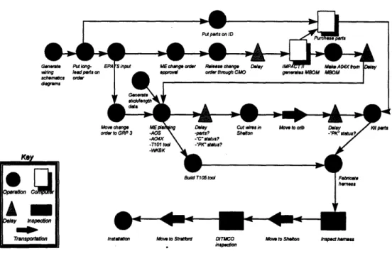
The harness development for each new customer encompasses nine major stages: generation of wiring diagrams, harness EPATS design, production illustration, harness manufacturing planning, wire cutting and coding, 2-D T105 tool construction, harness fabrication, harness installation planning, and installation. For each harness, the sequence of these stages is relatively sequential except for wire cutting/coding and T105 tool construction which are typically performed concurrently.
1. Generation of wiring schematics: The primary responsibility of the
electrical and avionics designers is to design every aspect of the wiring system associated with each customer order. The design describes every aspect of each wiring system and provides the necessary information needed to requisition all material (except for the length of wire).
2. Harness EPATS design: This task begins with the input of the electrical systems schematics,( i.e., the definition of all the electrical components and their pin to pin connections) into Sikorsky's Electrical Planning and Tooling System (EPATS). The primary output of this activity constitutes the complete design of all the wiring harnesses in the aircraft. EPATS interfaces with Sikorsky's MRP II system (IMPACT II) and generates an engineering bill of material that will requisition parts.
3. Production illustration: This step has been eliminated by the DMC II in order to save limited engineering resources on producing detailed installation drawings to build only one or two aircraft. Engineers, still, however, through past experience and existing drawings are required to provide a detailed stick diagram of the harness layout depicting routing information and wire lengths.
When there is still too much uncertainty in the exact harness routing path, engineers will make long wire estimates which will require connectors to be terminated in the aircraft during harness installation.
4. Harness manufacturing planning: Length data for each wire is manually entered into a computer program that will automatically generate a two dimensional stick diagram for each harness assembly. This stick is then
manipulated (bent) on a 2-D drawing program so that its full-size print out will fit on 3'x 8' harness board sections. The harness planner also details the fabrication plan that defines the steps, processes, and sequence of all the individual tasks associated with fabricating the harnesses on the boards.
5. Wire cutting and coding: For each harness, a wire cutting work order is entered into the MRP II system that will generate a requirement for wires to be cut and coded at the Avionics Systems Center in Shelton, CT. EPATS data is directly transferred to automated CAPRIS wire cutting machines. The wires are then transported back to Stratford for harness fabrication.
6. 2-D T105 tool construction: The 2-D drawings created by the harness planners are manually attached to 3' x 8' plywood boards to create a harness board. Clips and pins are added to the boards at specified locations to support the routing of wires.
7. Harness fabrication: Hourly technicians manually route wires as per the assembly operation sheets created by the harness planners. Connectors, ties, and proper shieldings are added to complete the harness assembly. The harnesses are then inspected after fabrication and typically sent back to
8. Harness installation planning: Installation operation sheets are created to define the steps, processes, and sequence of all the jobs associated with the installation of the wire harness. (2-D illustration drawings to guide the factory workers to install the wire harnesses into the airframe are generally not created in the DMC II. The designer usually goes to the aircraft to answer any
questions the technician installing the harness may have.)
9. Harness installation: This step constitutes the actual installation of the harnesses into the aircraft. Many of the harnesses are routed based on
engineering guidance during construction. Considerable harness rework occurs during this step for "first of a kind" harnesses due to uncertainty in wire
routing and wire length data.
3.2.2. Organizational structure
The organizational structure of Sikorsky's Development Operations is divided into two units, the DMC II and the DMC. The entire organization is overseen by one vice president responsible for the cost, delivery, and schedule for all development programs. A second engineering vice president is responsible for both product safety and technical support for DMC II programs.
3.2.2.1. DMC H organizational structure
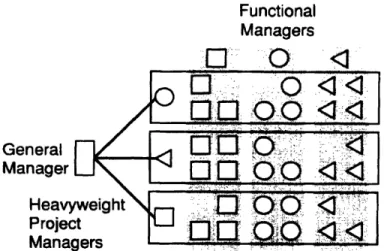
The organizational structure within the DMC II is based on a "heavyweight project organization" model as shown in Figure 3-2 below.
Functional Managers General Manager
Heavyweight
.•
0
Project ' ManagersFigure 3-2: Heavyweight product development organization.'
As a "heavyweight project organization", the DMC II provides the integration, speed, and coordination benefits associated with true project organizations, but still retains some of the specialization of Sikorsky's functional departments. Consequently, as the DMC II grows, it will require more managers and administrators than that of a truly non-matrix organization. Since the lead functional representatives in the DMC II are evaluated by only the DMC II manager and not their functional departments, much of the conflict between balancing functional responsibilities and project responsibilities
(typically associated with true matrix organizations) has been eliminated. With product development speed being one of the overriding tenants crucial to the success of the DMC II, the heavyweight project organization model has thus far proven successful in quickly resolving conflicts between functional representatives and for efficiently coordinating activities between individuals with different functional backgrounds. Overall, relatively little time is spent transferring information, assigning responsibilities, and coordinating tasks between members within the DMC II. Furthermore, over this seven month study, the DMC II continued to develop and refine its processes thereby further speeding coordination time. There are, however, challenges confronting the DMC II that are consistent with organizations modeled along project lines. For example, a project may only require a portion of an electrical engineer's time for a fraction of the duration of a
9 Adapted from Karl T. Ulrich and Steven D. Eppinger, Product Design and Development (New York: McGraw-Hill, 1995) 27.
project. In the past, Sikorsky had handled this problem by assigning electrical engineers to a functional department so that several projects could draw on the electrical engineer
resource in exactly the amount needed for a particular project. Today, however, in the DMC II environment, engineers are expected to take on broader job responsibilities and flexibly adapt to project needs (sometimes even across multiple projects).
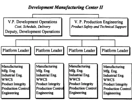
Within the DMC II, platform leaders are identified for each individual program. These platform leaders are held accountable for all aspects of their program and are evaluated based on how well their program adheres to safety, compliance, cost and delivery schedules. In theory, each platform leader has control over all of the critical resources needed for program success. As depicted in Figure 3-3, these resources
include: manufacturing, manufacturing engineering, industrial engineering, world wide customer service, product integrity, production control, and engineering.
Development Manufacturing Center II
V.P. Development Operations V. P. Production Engineering
Cost, Schedule, Delivery Product Safety and Technical Support
Deputy, Development Operations
Platform Leader Platform Leader Platform Leader Platform Leader
Manufacturing Manufacturing Manufacturing ManufacturingMfg. Eng. Mfg. Eng. Mfg. Eng. Mfg. Eng.
Industrial Eng. Industrial Eng. Industrial Eng. Industrial Eng.
WWCs wwCs wwCs wwCs
Product Integrity Product Integrity Product Integrity Product Integrity Production Control Production Contro Production Control Production Control Engineering Engineering Engineering Engineering
Figure 3-3: Development Manufacturing Center II Organizational Chart
Over my seven month stay within the DMC II, the organization nearly doubled in
size and platform leaders began to compete for limited personnel resources. Within the
DMC II, there are individuals who are designated as Core Team Members. Each of the major functions was headed by a Core Team Member who was considered the process owner for that particular function. Moreover, they were responsible for interacting withtheir old functional organizations to request additional manpower and technical support. In effect, they served as "working" functional managers within the DMC II. Core Team Members were not evaluated by their functional departments, but worked directly for the DMC II manager. The majority of the growth within the DMC II during my tenure was attributed to the temporary transfer of design engineers to work on new programs for the DMC II Core Members. These engineers, however, were still evaluated by their
functional organizations and were not considered Core DMC II Team Members.
3.2.2.2. Wiring harness organization structure
The nine major stages of the harness development process are performed by three departments: the DMC II, the Avionics Systems Center, and the DMC. The DMC II is responsible for the generation of wiring schematics, EPATS design, production
illustrations, and harness installation planning. The DMC generally completes harness manufacturing planning, 2-D T105 tool construction, harness fabrication, and harness installation, while the Avionics Systems Center is responsible for wire cutting and coding and DITMCO testing.
The organizational structure defining the harness development process is somewhat complex and is not accurately depicted in the DMC II organizational chart shown previously. Most programs have one electrical engineer (job classification C5) with overall responsibility for the EPATS design for that program. At the time of this study, only one EPATS designer was considered a Core DMC II Member. Others were brought in temporarily on an "as needed" basis. Some were co-located within the DMC II; others remained in their functional areas. During my stay, some of the EPATS design work was even outsourced to a nearby contractor due to perceived manpower constraints.
Similarly, there was only one systems manufacturing engineer who was a Core DMC II Member. He was identified as the process owner for the portion of the harness development process that remained after the design was complete. His job was
noticeably challenging because he still had to work across functional barriers to get work accomplished. For example, harness manufacturing planning, wire cutting, and harness
fabrication were performed by individuals outside of the DMC II who were still evaluated by their functional organizations.
3.3.
Cycle time reduction of wiring harness development
Reducing the cycle time of the harness development process is critical to achieving the target 30% reduction in aircraft delivery time. Since the electrical and avionics systems ultimately define the wiring functionality and the airframe structure defines the geometric space, harness development is forced to come after the electrical systems, avionics systems, and the aircraft structure have been designed. Historically, harness development has been the longest individual development process for each customer, often requiring more than a year to complete for derivative aircraft. In addition, wiring systems have the highest degree of variation from one customer to the next, where roughly 1/4 to 1/3 of all wiring harnesses undergo some design modification. Finally, the harness development process is considered to be the longest segment of the critical path, spanning over 70% of the total customer order cycle time.
Further reducing cycle time of harness development in the DMC II presents a number of significant obstacles. First and foremost, harness development is a large and
complex task. The design of each customer's wiring system travels through a year (or longer) development process and is touched by numerous engineers and technicians. Each activity depends greatly on data from multiple upstream groups, and its data in turn feeds a number of downstream activities. This creates a complex web network of
suppliers and customers that differs considerably from project to project. Moreover, almost no single person understands the entire process because individual workers and managers have been traditionally measured on their functional needs and requirements.
Even with all of the radical organizational changes made with the formation of the DMC II, portions of the organization are still split along functional lines. This is
attributed to the fact that historically wiring development has been conducted in a very serial fashion. One reason for this serial flow was to allow each functional group to develop a well integrated, aircraft wide solution before passing its data on to the next function. It also facilitated the development of functional experts who spent years
learning the processes and the dedicated computer tools which optimize their particular function's development process. This serial flow proved sufficient for production aircraft and production changes, but was wholly inadequate for the flexibility required in the DMC II.
Within the fast-paced, mod-shop environment of the DMC II, the functional mindset creates problems. Although a large amount of design integration is needed within each function, there are also many issues of design integration across functions that must be conducted quickly and efficiently in order to meet customer delivery and cost requirements. For example, the EPATS designer may decide which harness will connect two components. If he specifies that the connection will be integrated into an existing wiring harness, he may greatly influence the routing of the harness, which is within the domain of the engineer designated to provide stick information as well as the technician tasked to install the harness. Gathering and balancing information from these downstream customers is crucial to meeting cycle time improvement targets. In the past, Sikorsky had the luxury of spending considerable amounts of time perfecting designs prior to releasing them downstream. Similarly, they had the time necessary to follow detailed engineering change procedures when problems were found with designs. Slow feedback loops throughout the entire process drove a significant amount of rework into every functional group thereby considerably lengthening development cycle time. Today, however, in the DMC II that luxury is no longer feasible. Teamwork and efficient
collaboration between all functions is necessary to meet demanding customer needs. To date, the DMC II organization has taken enormous strides in breaking down functional silos; however, silos still do exist.
Amidst all these challenges, the management of the DMC II accepted the goal of drastically reducing its cycle time. The following chapters integrate the methodology for addressing development cycle time described in Chapter 2 with the DMC II's harness development process.
4.
Cycle time reduction methodology applied to S70 wiring
harness development
This chapter applies the cycle time reduction methodology presented in Chapter 2 to the harness development process in the DMC II. It also describes a queuing network model and simulation program that was used in pursuit of further incremental and radical improvement. The benefits of simulation based on queuing network theory when
addressing development cycle time will be explained by contrasting it to existing project management tools such as Gantt and PERT charts.
4.1.
Develop systems view of harness development process
Using the concept of the "Rework Cycle" described in Chapter 2, the harness development process can be modeled as follows:
Manpower Productivity Quality
Rework discovery
Figure 4-1: "Rework Cycle" applied to harness development process.
The model shown above keeps account of the harnesses that have been developed and the work that remains to be done within a development program. For example, a helicopter development program has two pools of harnesses that need to be developed. They are:
1. The harnesses initially identified as needing to be developed. The harnesses in this pool are those which have not been started by engineering. These harnesses include completely new designs as well as similar designs used on other programs that will be modified.
2. The backlog of rework. The harnesses in this backlog are those that have been identified as requiring rework due to engineering changes, inadequate length information, or a variety of other quality flaws in the fabrication process.
Similarly, there are two pools of "harnesses developed":
1. Undiscovered rework. The harnesses in this pool have started the
development process and will require revision, but have not yet been identified as requiring rework. After the need for rework is perceived, these harnesses become part of the recognized backlog of rework in the pool of "known rework."
2. Harnesses actually developed. This pool represents harnesses that have been completed, tested, and will not require revision.
The rate of "harnesses being developed" decreases the harness backlogs and adds to the levels of completed harnesses. The rate of accomplishment (in terms of harnesses designed, planned, fabricated, or installed per time period) depends upon the number of people working and their average productivity. As harnesses are developed, they flow to "undiscovered rework" or "harnesses actually developed" depending on "quality."
Quality, in this example, represents the fraction of harnesses that will not require rework. The model represents within its structure the behavior of the principal factors affecting
quality and productivity in each different phase of the harness development process, such as: manpower skill levels, upstream work availability and correctness, suppliers designs, material availability, and other organizational conditions. These factors represent the