Adolphe Merkle Institute University of Fribourg (Switzerland)
Physiologically Responsive Mechanically Adaptive Polymeric Materials
for Biomedical Applications
THESIS
Presented to the Faculty of Science of the University of Fribourg (Switzerland) in fulfillment of the requirements for the academic grade of Doctor of Science
Doctor rerum naturalium,Dr. rer. nat.
by
Mehdi Jorfi
Thesis No: 1829 University of Fribourg
Accepted by the Faculty of Science of the University of Fribourg (Switzerland) upon the recommendation of
• Prof. Dr. Christoph Weder, Adolphe Merkle Institute, University of Fribourg, Switzerland (Thesis Supervisor)
• Dr. E. Johan Foster, Adolphe Merkle Institute, University of Fribourg, Switzerland (Internal Co-Examiner)
• Prof. Jeffrey R. Capadona, Department of Biomedical Engineering, Case Western Reserve University, USA (External Co-Examiner)
• Prof. Nico Bruns, Adolphe Merkle Institute, University of Fribourg, Switzerland (President of Jury)
Fribourg, 25/03/2014
Thesis Supervisor
Prof. Dr. Christoph Weder Dean
Dedication
This dissertation is dedicated to my mother, who through her invaluable actions has taught me that anything is possible as long as you work hard. This dissertation also dedicated to my family. Their support and encouragement have sustained me throughout my life.
Acknowledgements
This was made possible by the assistance and contributions of many others. Most notably, my supervisor, Prof. Christoph Weder, who has been an extraordinary mentor and helped me to guide this work through many twists and turns. I learned tremendously from him in many ways. The robustness and thoroughness of his work is something I will always try to apply in my own work. His technical insights and contributions were important, and so his broader knowledge about science and career development. I have often admired his excellence in writing which have shaped this work into something much better than what I could have done myself. Chris has a great ability to guide his students, while retaining the patience to allow students to develop their own interests and become capable independent researchers. I am forever grateful for the privilege of working with him.
I would like to thank my group leader, Dr. Johan Foster, for many things. Among them: his scientific creativity and fearlessness to tackle any challenge, his infectious enthusiasm towards science, and his dedication to support his students to be even better than they think they could be. I am also thankful for his personal attention, suggestions, endless encouragement and full support during last years of my Ph.D. research. I am fortunate to have been part of his group during its amazing growth.
My other committee member, Prof. Jeffrey Capadona, has provided valuable comments and has shown a great deal of patience and support as my project developed over time. I appreciate his time out of busy schedules to provide helpful criticisms, comments, and feedback regarding my thesis projects.
This interdisciplinary research would not have been possible without the help of many brilliant colleagues and collaborators. In particular, Dr. Jeff Capadona has been a valuable collaborator on several of my cortical implant projects. I would like to gratefully acknowledge all the members of the Capadona Lab for their contributions, helpful discussions, and their kind host during my trip to Cleveland. In particular, I am grateful to
Kyle Householder, Jessica Nguyen, and Kelsey Potter who worked closely with me throughout my drug-releasing materials’ project.
AMI has been a great place to grow and develop as a scientist. I want to thank all the members of the Chris Lab with whom I had a pleasure to discuss science and collaborate with. Many researchers of Chris Lab have directly or indirectly contributed to my research at AMI. I would like to thank especially Pratheep Annamalai, Mahesh Biyani, Matt Roberts, Janak Sapkota, Apiradee Nicharat and Tobias Kuhnt for all the fruitful collaborative works we have done together. I also owe special thanks to all Polymer Chemistry and Materials’ group members, especially Soo, Christian, Silvana, Sonja, Sandeep, Sandra and Souleymane for good times, support and friendship. I would like to extend my thanks to Katharina Gries for translating my thesis abstract into German language and Rebecca Parkhurst who helped me proofread the present dissertation’s conclusions and outlook. Also, I would like to express my gratitude to all AMI colleagues for maintaining friendly atmosphere throughout my work.
Lastly, I would like to thank my family for inspiration and support received throughout these years. I believe this achievement is theirs as much as it is mine. Most importantly, my mother, for her decades of love and support, for her smiles and tears throughout my studies and the several years that I have been away from home. My mother has always supported my ambitions and it is because of her work and sacrifices that I am in this position today. Finally, my deepest appreciation goes to my lovely wife, Sarminaz, for providing constant support and encouragement, for her admiration, and her ever-positive attitude.
Physiologically Responsive Mechanically Adaptive Polymeric Materials
for Biomedical Applications
Mehdi Jorfi
University of Fribourg, 2014 Supervisor: Professor Christoph Weder
Abstract
Artificial neural interfaces can connect the central nervous system with the outside world and hold great potential for rehabilitating patients that suffer from paralysis, other forms of motor dysfunction, or limb loss. Several types of brain neural interfaces, with varying levels of invasiveness and abilities to acquire neural signals, have been developed. For example, non-penetrating recording electrodes placed externally on the scalp or subdurally on the brain surface can gain functional information. However, many researchers believe that recording and stimulating devices that penetrate into specific regions of the brain (i.e. intracortical microelectrodes) will likely provide the most useful signals for neural interfacing. Despite the potential that intracortical microelectrodes have shown, widespread clinical implementation is impeded by the fact that it is difficult to consistently record high quality neural signals over clinically relevant time frames. This is in large part due to neuro-inflammation, which involves both neuron degeneration and foreign body encapsulation. Several factors have been implicated to contribute to neuro-inflammation following device implantation, including the mechanical mismatch between the often highly rigid implant and the much softer brain tissue, and the oxidative stress state that forms around the implant as a result of inflammation. To enable long-term consistent neural recordings, new materials are needed for the next generation of intracortical microelectrodes, with an increased emphasis on reducing the neuro-inflammatory response.
x
This dissertation pursued the development of new physiologically responsive, mechanically adaptive polymeric materials for neural interfacing applications and the study of the structure-property relationships of these materials. Expanding a previously established design principle for chemo-responsive mechanically adaptive materials inspired by the architecture of the sea cucumber dermis, several families of nanocomposites were designed, prepared and studied. These materials consist of a matrix polymer that is reinforced with rigid cellulose nanocrystals (CNCs) and the interactions between the CNCs, and therewith the overall mechanical properties, can be influenced by exposure to water. The adaptive nature of these materials makes them useful as a basis for penetrating cortical microelectrodes that are sufficiently stiff to be easily implanted into the cortex, but upon exposure to physiological conditions soften to better match the stiffness of the brain. Several new rationally designed materials systems were investigated.
Thus, nanocomposites based on poly(vinyl alcohol) and CNCs derived from tunicates and cotton were studied to explore how aspect ratio, surface charge density, and filler content influence the mechanical properties. The new materials offer an initial stiffness that is significantly higher than that of previous generations of such responsive materials, presumably on account of polymer-CNC interactions. It was also shown that the aqueous swelling characteristics of the nanocomposites could be controlled via the processing conditions. Using this tool, the switching “contrast” of the nanocomposites upon exposure to (emulated) physiological conditions could be varied.
Physiologically responsive mechanically adaptive materials based on poly(vinyl alcohol) or poly(vinyl acetate) and CNCs isolated from tunicate or cotton were further bestowed with the capability to also locally administer the anti-oxidant drugs curcumin, resveratrol or superoxide dismutase mimetic with burst or sustained release profiles. These materials represent the first examples of materials for intracortical implants which combine two independently effective mechanisms – mechanical morphing and localized anti-oxidant release. They permit, for the first time, to explore if the combination leads to synergistic effects and will permit investigations of how the release kinetics of anti-oxidant therapies
at the intracortical implant-tissue interface influence neural integration. A first in vivo study of PVA/CNC/curcumin nanocomposites in rats revealed that over the first four weeks of the implantation, curcumin-releasing, mechanically adaptive implants were associated with higher neuron survival and a more stable blood-brain barrier at the implant-tissue interface than the neat poly(vinyl alcohol) controls.
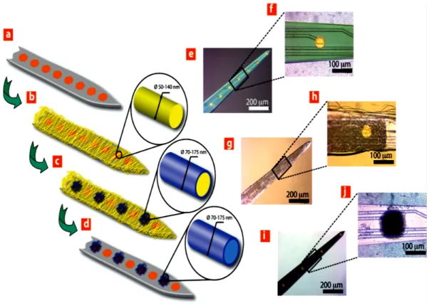
Finally, the ability to mechanically morph upon exposure to physiological conditions was imparted to optical fibers for optogenetics. This recently developed neural interfacing platform relies on the activation or muting of neurons using light and one must expect that mechanical mismatch of conventional optical fibers and the cortical tissue also contribute to the chronic neuroinflammatory response. Thus mechanically adaptive optical fibers made of PVA were developed, which may mitigate this problem. Produced by a one-step wet-spinning process, the fibers display an initial stiffness that is slightly higher than that of commercial optical fibers and permits facile insertion of small-diameter implants into the cortex. Upon exposure to (emulated) physiological conditions, the fibers swell slightly with water and their stiffness is reduced significantly, while the concomitant changes to the fiber’s optical properties are small. The PVA optical fibers permit to deliver light of a range of wavelengths that is sufficiently intense to stimulate neurons in the brain and meet the optical demands of optogenetic applications.
This dissertation derived fundamental insights into the structure-property relationships by governing the adaptive nature of these materials through composition (i.e. different polymer matrices, types and amount of nanofiller, and therapeutic agents) and also processing conditions. While in vivo studies using the new materials presented here have only begun, it is already clear that the materials made and studied in this dissertation will be useful to advance the understanding of how stimuli-responsive polymeric materials can help to decrease the neuroinflammation effects associated with intracortical implants.
Physiologisch Responsive Mechanisch Adaptive Polymere für
Biomedizinische Anwendungen
Mehdi Jorfi
Universität Freiburg, 2014 Betreuer: Professor Christoph Weder
Zusammenfassung
Künstliche neurale Schnittstellen können verwendet werden, um das zentrale Nervensystem mit der äusseren Welt zu verbinden. Sie bieten deshalb grosses Potential für die Rehabilitierung von Patienten, die unter Lähmung, anderen Formen von motorischer Dysfunktion oder Amputationen leiden. Es wurden verschiedene Arten neuraler Gehirnschnittstellen entwickelt, mit unterschiedlichen Invasivitätsgraden sowie der Fähigkeit, neurale Signale aufzunehmen. Beispielsweise können nicht-eindringende aufzeichnende Elektroden, welche extern auf der Kopfhaut oder subdural auf der Hirnoberfläche angebracht werden, funktionale Informationen gewinnen. Allerdings ist unter Forschern die Annahme verbreitet, dass Aufzeichnungs- und Stimulationsgeräte, die in spezifische Regionen des Gehirns eindringen (z. B. intrakortikale Mikroelektroden), wahrscheinlich die nützlichsten Signale einer neuralen Schnittstelle liefern werden. Trotz des Potentials, welches intrakortikale Mikroelektroden gezeigt haben, ist die breite klinische Implementation durch die Tatsache behindert, dass es schwierig ist, beständig qualitativ hochwertige neurale Signale über einen klinisch relevanten Zeitrahmen aufzuzeichnen. Dies wird hauptsächlich durch Neuroinflammation verursacht, was sowohl Neuronendegeneration als auch Fremdkörperverkapselung beinhaltet. Viele Faktoren werden in Zusammenhang gebracht, einen Beitrag zur Entzündung der Gehirnareale in Folge von Geräteimplantationen zu leisten, darunter die mechanische Diskrepanz zwischen dem häufig sehr steifen Implantat und dem deutlich weicheren Hirngewebe, sowie dem oxidativen Stresszustand, der um das Implantat als
Resultat der Entzündung entsteht. Um langzeit-beständige neurale Aufzeichnungen zu ermöglichen, werden neue Materialien für die nächste Generation intrakortikaler Mikroelektroden benötigt, mit grösserer Betonung auf einer Reduktion der neuroinflammatorischen Antwort benötigt.
Die vorliegende Dissertation verfolgt die Entwicklung physiologisch responsiver, mechanisch adaptiver Polymere für neurale Schnittstellenapplikationen sowie eine Studie zur Struktur-Eigenschaftsbeziehung dieser Materialien. Ausgehend von einem zuvor etablierten Designprinzip für chemisch-responsive mechanisch adaptive Materialien, inspiriert durch die Architektur der Dermis von Seegurken, wurden verschiedene Familien von Nanokompositen entworfen, präpariert und untersucht. Diese Materialien beinhalten ein Matrixpolymer, welches durch steife Cellulose Nanokristalle (cellulose nanocrystalls, CNCs) und die Wechselwirkungen zwischen den CNCs verstärkt wird, so dass auch die gesamten mechanischen Eigenschaften durch Kontakt mit Wasser beeinflusst werden können. Die adaptive Natur dieses Materials lässt es nützlich erscheinen als Basis für eindringende kortikale Mikroelektroden, die ausreichend steif sind, um einfach in den Kortex implantiert werden zu können, aber unter physiologischen Bedingungen erweichen und besser zur Steifigkeit des Gehirns passen. Mehrere neue, rational entworfene Materialien wurden untersucht.
Nanokomposite basierend auf Polyvinylalkohol (PVA) und CNCs, gewonnen aus Manteltieren und Baumwolle, wurden hinsichtlich des Einflusses von Aspektverhältnis, Oberflächenladungsdichte und Füllstoffkonzentration auf die mechanischen Eigenschaften untersucht. Die neuen Materialien bieten eine anfängliche Steifigkeit, welche signifikant höher ist als bei vorangegangenen Generationen solcher responsiver Materialien, vermutlich wegen der Wechselwirkungen zwischen Polymer und CNCs. Ferner wurde gezeigt, dass die Quellcharakteristika der Nanokomposite im wässrigen Medium durch die Verarbeitungsbedingungen kontrolliert werden konnten. Unter Verwendung dieses Instruments konnte der „Schaltkontrast“ der Nanokomposite durch Kontakt mit (emulierten) physiologischen Bedingungen variiert werden.
Physiologisch responsive mechanisch adaptive Materialien basierend auf Polyvinylalkohol oder Polyvinylacetat und CNCs, die aus Manteltieren oder Baumwolle gewonnen wurden, wurden so konzipiert, auch lokal die antioxidativen Wirkstoffe Curcumin, Resveratrol oder Superoxiddismutase mimetisch mit plötzlichen („burst“) oder nachhaltigen Freisetzungsprofilen zu regulieren. Diese Materialien repräsentieren die ersten Beispiele für interkortikale Implantate, welche zwei voneinander unabhängig effektive Mechanismen kombinieren – mechanische Verformbarkeit und lokale Freisetzung von Antioxidantien. Sie erlauben erstmals Untersuchungen darüber, wie die Freisetzungskinetik bei Antioxidanstherapie an der intrakortikalen Implantat-Gewebe Grenzfläche die neurale Integration beeinflusst. Eine erste in-vivo Studie mit PVA/CNC/Curcumin Nanokompositen an Ratten zeigte, dass über die ersten vier Wochen der Implantation Curcumin-freisetzende, mechanisch adaptive Implantate mit einer höheren Neuronenüberlebensrate und einer stabileren Blut-Hirn-Schranke an der Grenzfläche zwischen Implantat und Gewebe assoziiert wurden als die reinen Polyvinylalkohol Kontrollproben.
Abschliessend wurde die Fähigkeit der mechanischen Verformung durch Einfluss physiologischer Bedingungen für optische Fasern für die Optogenetik verwendet. Diese kürzlich entwickelte Plattform für neurale Schnittstellen beruht auf der Aktivierung oder Stummschaltung von Neuronen, die Licht verwenden. Es wird erwartet, dass die mechanische Diskrepanz zwischen konventionellen optischen Fasern und kortikalem Gewebe auch zur chronischen neuroinflammatorischen Antwort beiträgt. Daher wurden mechanisch adaptive optische Fasern aus PVA entwickelt, welche dieses Problem lindern könnten. Die Fasern wurden in einem einstufigen „dry-jet“ Nassspinnprozess produziert und sie zeigen eine anfängliche Steifigkeit, die geringfügig höher ist als die kommerziell erhältlicher optischer Fasern, und die müheloses Einführen von Implantaten mit geringem Durchmesser in den Kortex ermöglicht. Unter (emulierten) physiologischen Bedingungen quellen die Fasern mit Wasser geringfügig auf und ihre Steifigkeit wird signifikant reduziert, während die begleitenden Veränderungen der optischen Eigenschaften der Faser gering sind. Die optischen Fasern aus PVA erlauben es, Licht in einem
Wellenlängenbereich zu transportieren, der hinreichend intensiv ist, Neuronen im Gehirn zu stimulieren und optischen Anforderungen für optogenetische Anwendungen gerecht zu werden.
Die vorliegende Dissertation leitet fundamentale Einblicke in Struktur-Eigenschaftsbeziehungen her, indem sie die adaptive Natur dieser Materialien durch Zusammensetzung (z.B. unterschiedliche Polymermatrices, Art und Menge der Nanofüller und therapeutischer Substanzen) sowie die Verarbeitungsbedingungen vertieft. Während in-vivo Studien zum hier vorliegenden neuen Material gerade erst begonnen haben, ist es schon heute ersichtlich, dass die im Rahmen dieser Dissertation hergestellten und untersuchten Materialien zum Fortschritt des Verständnisses nützlich sind, wie stimuli-responsive Polymere helfen können, neuroinflammatorische Effekte in Zusammenhang mit Intrakortikalimplantaten zu verringern.
Table of Contents
List of Tables ... xix
List of Figures ...xx
List of Abbreviations ... xxix
Chapter 1 – Introduction to Biocompatible Materials for Intracortical Microelectrodes ...1
1.1. TRADITIONAL INTRACORTICAL MICROELECTRODES FOR BRAIN MACHINE INTERFACING ...2
1.2. CHALLENGES TO OBTAINING CONSISTENT, HIGH-QUALITY NEURAL RECORDINGS ...4
1.2.1. The Neuro-Inflammatory Response ...5
1.3. MATERIAL STRATEGIES FOR IMPROVING MICROELECTRODE BIOCOMPATIBILITY AND RECORDING PERFORMANCE ...5
1.3.1. Mechanically Compliant Intracortical Microelectrodes ...7
1.3.1.1. Introduction to Microelectrodes Mechanics ...8
1.3.1.2. Compliant Polymeric Materials for Intracortical Microelectrodes ...10
1.3.1.3. Insertion Aides and Biodegradable Materials ...16
1.3.1.4. In Situ Softening Materials ...19
1.3.2. Incorporating Bioactive Materials ...30
1.3.3. Conducting Polymers ...37
1.3.4. Nanomaterials ...46
1.4. REFERENCES ...57
Chapter 2 – Scope and Objectives ...67
Chapter 3 – Physiologically Responsive Mechanically Adaptive Bio-Nanocomposites for Biomedical Applications ...69
3.1. ABSTRACT ...69
3.2. INTRODUCTION ...70
3.4. RESULTS AND DISCUSSION ...77
3.4.1. Isolation and Physical Properties of Cellulose Nanocrystals ...77
3.4.2. Nanocomposite Processing ...78
3.4.3. Thermal Properties ...79
3.4.4. Mechanical Properties of Dry PVA/CNC Nanocomposites ...79
3.4.5. Analysis of Mechanical Data in the Framework of the Percolation Model ...85
3.4.6. Swelling Behavior ...88
3.4.7. Mechanical Properties of ACSF-Swollen Nanocomposites ...90
3.5. CONCLUSIONS ...93
3.6. REFERENCES ...95
3.7. APPENDIX ...98
Chapter 4 – Curcumin-Releasing Mechanically Adaptive Intracortical Implants Improve Proximal Neuronal Density and Blood-Brain Barrier Stability ...105
4.1. ABSTRACT ...105
4.2. INTRODUCTION ...106
4.3. EXPERIMENTAL SECTION ...108
4.4. RESULTS ...117
4.4.1. Characterization of Curcumin-Loaded Materials ...117
4.4.2. Mechanically Adaptive Properties of Materials ...118
4.4.3. Curcumin Release Profiles ...120
4.4.4. Anti-oxidative Activity of Curcumin-Loaded Materials ...121
4.4.5. In vivo Studies ...121
4.4.6. Neuronal Nuclei Density (NeuN) ...121
4.4.7. Blood Brain Barrier Permeability (IgG) ...125
4.4.8. Astrocytic Scar Formation: Astrogliosis (GFAP) ...127
4.4.9. Microglia and Macrophage Density ...129
4.4.10. Wound Healing (HMGB-1) ...131
4.5. DISCUSSION ...133
4.7. REFERENCES ...142
4.8. APPENDIX ...146
Chapter 5 – Physiologically Responsive Mechanically Adaptive Antioxidant-Releasing Nanocomposites for Cortical Implants with Improved Neural Integration ...154
5.1. ABSTRACT ...154
5.2. INTRODUCTION ...155
5.3. EXPERIMENTAL SECTION ...156
5.4. RESULTS AND DISCUSSION ...161
5.4.1. Processing and Characterization of Materials ...161
5.4.2. Mechanically Adaptive Properties of Antioxidant-Loaded Materials ...165
5.4.3. Drug Release Studies ...168
5.4.4. Antioxidative Activity of Drug-Loaded Nanocomposites ...171
5.5. CONCLUSIONS ...175
5.6. REFERENCES ...176
5.7. APPENDIX ...177
Chapter 6 – Physiologically Responsive Mechanically Adaptive Polymer Optical Fibers for Optogenetics ...178
6.1. ABSTRACT ...178
6.2. INTRODUCTION ...179
6.3. EXPERIMENTAL SECTION ...180
6.4. RESULTS AND DISCUSSION ...182
6.5. CONCLUSIONS ...189
6.6. REFERENCES ...190
Chapter 7 – Conclusions and Outlook ...192
7.1. CONCLUSIONS ...192
7.2. OUTLOOK ...195
List of Tables
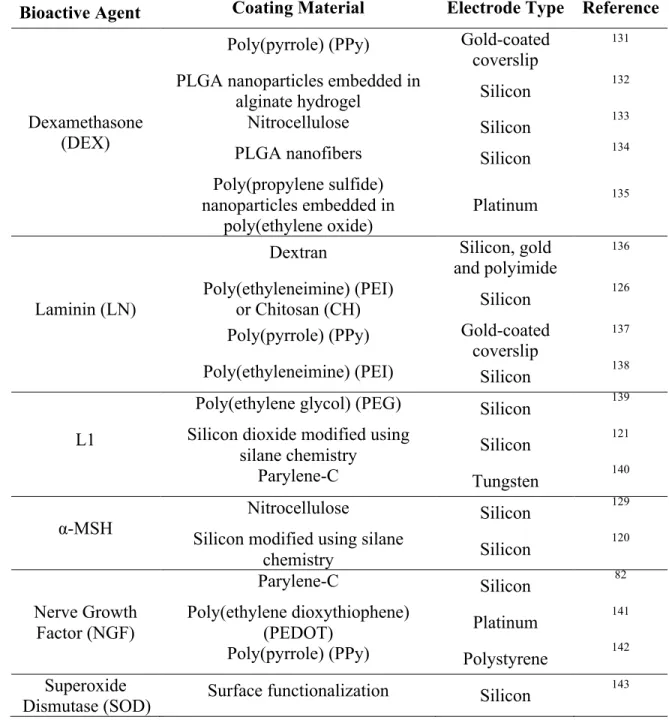
Table 1-1. Non-Exhaustive List of Bioactive Surface Treatments for Intracortical
Microelectrodes. ... 31
Table 3-1. Thermal properties of neat PVA and PVA/CNC nanocomposites as a function of CNC type and content. ... 80
Table 3-2. Tensile storage moduli of dry and ACSF-swollen films of neat PVA and PVA/CNC nanocomposites determined by DMA. ... 81
Table 3-3. Comparison of tensile storage moduli of current materials with previous mechanically-adaptive nanocomposites. ... 85
Table 3-4. Swelling data of neat PVA and PVA/t-CNC nanocomposites at 37 °C in ACSF as a function of t-CNC content. ... 90
Table 4-1. Swelling properties of neat PVA and curcumin-loaded films. ... 118
Table A4-1. Thermal properties of materials studied. ... 153
Table A4-2. Tensile storage moduliof dry and ACSF-swollen films determined by
dynamic mechanical analyzer ... 153
Table 5-1. Storage moduli of dry and ACSF-swollen PVAc/CNC nanocomposites determined by DMA. Data represent averages and are shown for the neat PVAc/CNC reference nanocomposite as well as for curcumin (Cur) and resveratrol (Res) releasing nanocomposites loaded with different contents of these antioxidants. ... 165
Table 5-2. Cumulative release (%) data of curcumin (Cur)-loaded PVAc/CNC
nanocomposites and resveratrol (Res)-loaded PVAc/CNC nanocomposites in ACSF at 37 °C determined by UV-vis.. ... 168
xx
List of Figures
Figure 1-1. Electrical circuit model of intracortical microelectrode in the brain. ... 4
Figure 1-2. Forces acting on the intracortical microelectrodes upon penetration. ... 9
Figure 1-3. Chemical structures of compliant polymeric materials and monomers
commonly used for neural interfaces. ... 11
Figure 1-4. SEM pictures of microelectrode tips of SU-8-based electrodes.. ... 15
Figure 1-5. Top: Pictures of a sea cucumber, in the threatened (stiff) and relaxed (soft) and state. Bottom: Simplified schematic representation of the switching mechanism found in the sea cucumber dermis and used in physiologically responsive mechanically-adaptive nanocomposites ... 20
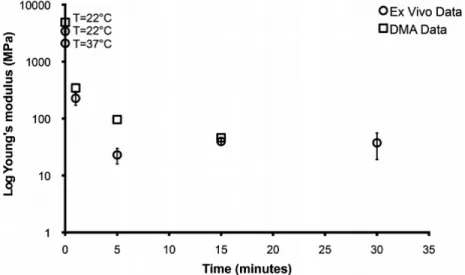
Figure 1-6. Plot showing the log of the Young’s modulus of mechanically adaptive PVAc/CNC nanocomposites as function of exposure time to ACSF or implantation time in the rat cortex. ... 22
Figure 1-7. Photograph of a 2-electrode contact intracortical probe. ... 24
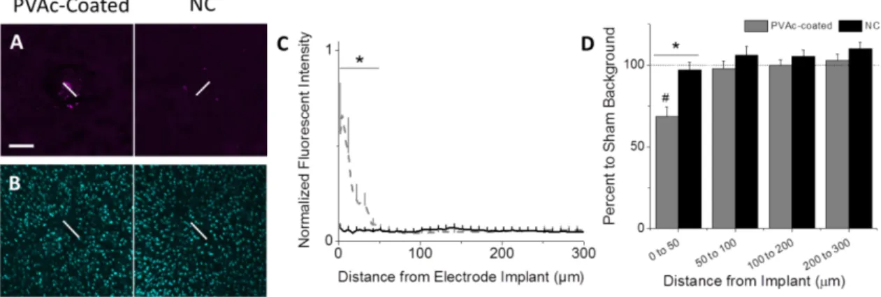
Figure 1-8. PVAc/CNC nanocomposite implants (NC) reduce chronic
neuroinflammation. ... 25
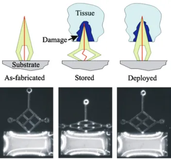
Figure 1-9. Schematic and light micrographs of a prototype SMP neuronal probe ... 26
Figure 1-10. Picture (left) and optical microscope image (right) of a mechanically adaptive cortical probe with 8 recording channels fabricated from a shape-memory polymer by transfer-by- polymerization process ... 27
Figure 1-12. (a, b) Representative images of NeuN+ cells (green) around the NM (unmodified) and L1 (L1-peptide grafted) probes after 8 weeks of
implantation in rat cortex. (c, d) Representative images of neuronal filament (green) stained tissue after 8 weeks of implantation in rat cortex ... 35
Figure 1-13. Chemical structures of poly(pyrrole) (PPy) and poly-(3,4-ethylene
dioxythiophene) (PEDOT), examples of conducting polymers explored in neural interfaces. ... 38
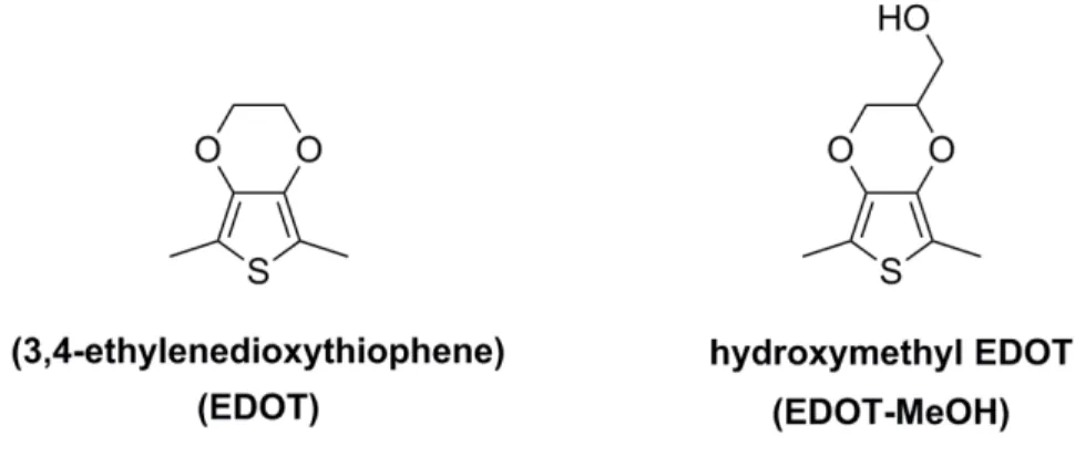
Figure 1-14. Chemical structures of monomers used to fabricate PEDOT and PEDOT-MeOH. ... 41
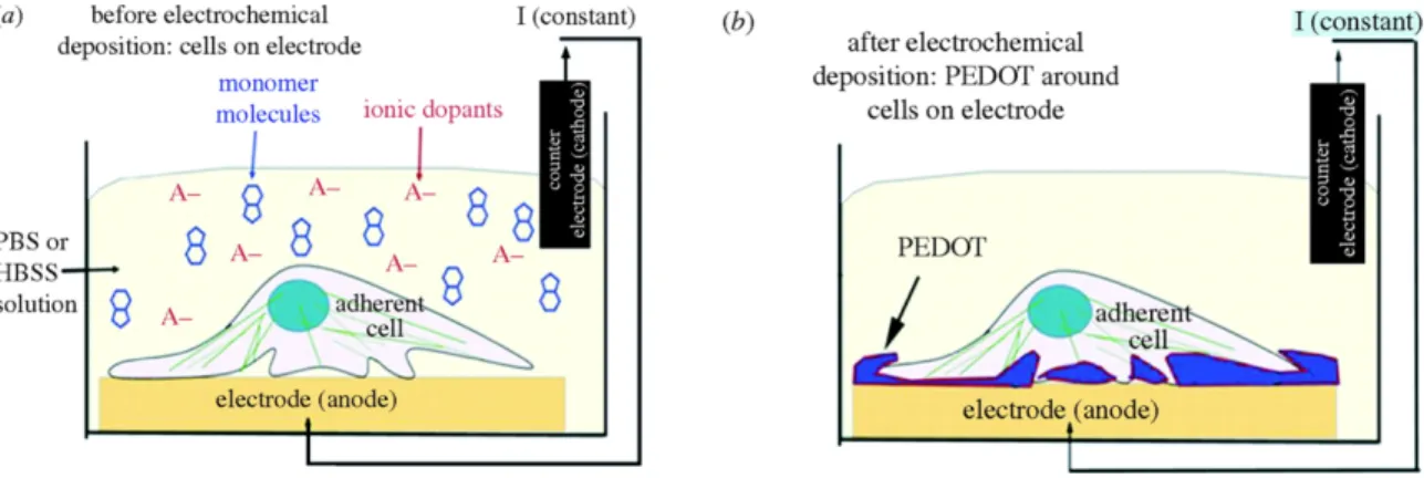
Figure 1-15. (a) Schematic of the electrochemical deposition cell and the neural cell monolayer cultured on the surface of the metal electrode prior to
polymerization. (b) PEDOT polymerized around living cells. ... 42
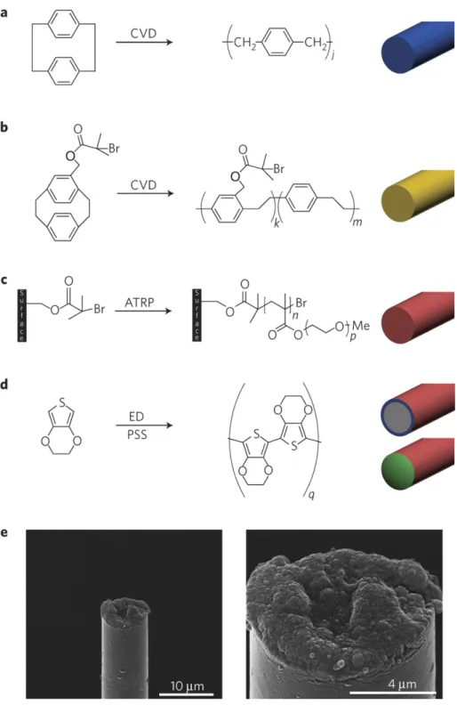
Figure 1-16. (a–d) Schematic representation of the fabrication of microtherad electrodes, and (e) SEM images of a fully assembled, functional electrode.. ... 44
Figure 1-17. GFAP immunostaining for the Pt implant control (A) and PPy/SWCNT coated Pt implant (C) after 6 weeks post-implantation. (E) Quantitative comparison of GFAP immunoreactivity between the control and coated electrodes as a function of distance from the electrode. The survival of neurons around the implanted electrode for the control (B) and coated implant (D) at 6 weeks post-implantation. (F) Quantification comparison of neuron survival between the control and coated electrodes as a function of distance from the electrode. ... 49
Figure 1-18. Scanning electron microscopy images of (a) An as-grown CNF array. (b) An as-grown CNF array after being soaked in water and then dried in the air. (c, d) an as-grown CNF arrays after electrodepositing a 40-nm-thick conformal polypyrrole film ... 51
Figure 1-19. Schematic represents fabrication of multifunctional biomaterial-based microelectrode. (A) Uncoated microelectrode. (B) Electrospining of drug-loaded nanofibers. (C) Hydrogel coating. (D) Electrochemical
polymerization of a conducting polymer. ... 53
Figure 1-20. Schematic illustration of conducting polymer (PEDOT) nanotube
fabrication on neural microelectrodes. ... 54
Figure 1-21. Scanning electron microscopy images of conducting polymers after CV measurements on a neural electrode. ... 55
Figure 3-1. AFM amplitude images for (a) lyophilized t-CNCs, and (b) spray-dried c-CNCs. ... 78
Figure 3-2. Dynamic mechanical analysis (DMA) data of dry PVA and dry PVA/CNC nanocomposites as a function of temperature and CNC content ... 83
Figure 3-3. (a) Tensile storage moduliof neat PVA and PVA/t-CNC nanocomposites as a function of CNC content in the dry state at 100 °C ( ), re-dried after
swelling with ACSF for 1 week ( ), ACSF-swollen after immersion in ACSF at 37 °C for 1 week ( ) and 1 month (Δ). (b) Tensile storage moduli of neat PVA and PVA/c-CNC nanocomposites as a function of CNC content in the dry state at 100 °C ( ), and ACSF-swollen after immersion in ACSF at 37 °C for 1 week ( ).. ... 88
Figure 3-4. Swelling of PVA/t-CNC nanocomposites compression-molded at 150 °C ( ), PVA/c-CNC nanocomposites compression-molded at 120 °C ( ), a PVA/t-CNC nanocomposite compression-molded at 120 °C ( ), and a PVA/c-PVA/t-CNC nanocomposite compression-molded at 150 °C ( ) as a function of CNC content, after the samples were immersed in ACSF at 37 °C for 1 day. ... 89
Figure 3-5. Dynamic mechanical analysis (DMA) data of ACSF-swollen films of (a) neat PVA and PVA/t-CNC nanocomposites and (b) PVA/c-CNC nanocomposites as a function of temperature and CNC content after immersion in ACSF at 37 °C for 1 week. ... 92
Figure A3-1. Conductometric titration curves of CNCs. (a) Lyophilized t-CNCs, (b) spray-dried c-CNCs, (c) lyophilized c-CNCs, and (d) a blank titration
without CNCs. ... 99
Figure A3-2. Representative transition electron microscopy (TEM) images of CNCs. (a) lyophilized t-CNCs, and (b) spray-dried c-CNCs. ... 99
Figure A3-3. Transition electron microscopy (TEM) images lyophilized c-CNCs. ... 100
Figure A3-4. Three-dimensional AFM topographic (height) images for (a) lyophilized t-CNCs, and (b) spray-dried c-CNCs. ... 100
Figure A3-5. Photographs of solution-cast and compression-molded PVA/c-CNC nanocomposite films (16% v/v c-CNCs) processed at 120 (left) and 150 °C (right), respectively. ... 101
Figure A3-6. DSC thermograms (second heating) of (a) PVA/t-CNC and (b) PVA/c-CNC nanocomposites and neat PVA films compression-molded at (a) 150 °C and (b) 120 °C, respectively. ... 102
Figure A3-7. Chart showing the stress-strain curves of neat PVA and PVA/CNC
Figure A3-8. DMA data of ACSF-swollen films of neat PVA and PVA/t-CNC
nanocomposites after immersion in ACSF at 37 °C for 1 month. ... 103
Figure A3-9. DMA data of ACSF-swollen films of 16% v/v PVA/t-CNC
nanocomposites after immersion in ACSF at 37 °C for 1 day. ... 103
Figure A3-10. DMA data of ACSF-swollen films of 16% v/v PVA/c-CNC
nanocomposites after immersion in ACSF at 37 °C for 1 day. ... 104
Figure 4-1. Chemical structure of poly(vinyl alcohol) (PVA) and curcumin. ... 108
Figure 4-2. Representative dynamic mechanical analysis (DMA) traces showing the tensile storage moduli of (A) dry and (B) ACSF-swollen curcumin-loaded poly(vinyl alcohol) (PVA) samples as a function of temperature and
curcumin content (1 or 3% w/w). ... 119
Figure 4-3. Cumulative in vitro release profile of curcumin-loaded polymers in ACSF at 37 °C. ... 120
Figure 4-4. (A) Plot showing the absorbance at 516 nm of a methanolic solution of DPPH (100 µM) as a function of time, and of the same solution in the presence of films consisting of neat PVA, or PVA with 1 or 3% w/w curcumin, respectively, incubated at 37 °C in the dark for up to 48 hours. (B) DPPH scavenging activity calculated from the results shown in (A). .. 122
Figure 4-5. Neuronal nuclei populations surrounding neat PVA control and curcumin-releasing PVA implants. Neuronal (NeuN) density was investigated at 2, 4 and 12 weeks after polymer implantation up to 600 μm from the implant interface. ... 125
Figure 4-6. Infiltration of immunoglobulin-g (IgG) around neat PVA controls and
Figure 4-7. Astrogliosis surrounding neat PVA control and curcumin-loaded PVA
implants in the cortex. ... 128
Figure 4-8. Total microglia and macrophage accumulation (IBA-1+
cells) around neat PVA controls and curcumin-releasing polymer implants. ... 130
Figure 4-9. Accumulation of activated microglia and macrophages (CD68+
) around neat PVA controls and curcumin-releasing implants. ... 131
Figure 4-10. Expression of High Mobility Group Box-1 (HMGB-1) around neat PVA controls and curcumin-releasing PVA implants. ... 132
Figure A4-1. (Left) AFM height image of CNCs derived from tunicates. ... 147
Figure A4-2. Conductometric titration curve of lyophilized CNCs.. ... 147
Figure A4-3. Representative dynamic mechanical analysis (DMA) traces showing the tensile storage moduli of (A) dry and (B) wet curcumin-loaded PVA/CNCs polymers as a function of temperature. ... 148
Figure A4-4. Cumulative in vitro release profile of curcumin-loaded materials in ACSF at 37 °C. ... 149
Figure A4-5. (Top) Chemical structure of DPPH and its reaction with an anti-oxidant (AO-H). (Bottom) Representative photographs of solutions of DPPH in methanol (100 μM, 3 mL) at 0, 9, 24 and 48 hours and after placing a film of the neat PVA control, or the curcumin-loaded PVA films into the DPPH solution.. ... 150
Figure A4-7. (A) Plot showing the absorbance at 516 nm of a methanolic solution of DPPH (100 µM) as a function of time, and of the same solution in the presence of films consisting of the neat PVA/CNC nanocomposite, or the PVA/CNC nanocomposites with 1 or 3% w/w curcumin, respectively, incubated at 37 °C in the dark for up to 48 hours. (B) DPPH scavenging activity calculated from the results shown in (A). ... 152
Figure 5-1. Chemical structures of materials used in this study. ... 157
Figure 5-2. Atomic force microscopy (AFM) image of lyophilized CNCs isolated from tunicates. The CNCs were deposited from aqueous dispersions (0.01
mg/mL) onto freshly cleaved mica surfaces. ... 162
Figure 5-3. Photographs of solution-cast PVAc/CNC nanocomposite films (15% w/w CNCs) with either 0.005% or 0.01% w/w resveratrol (Res, A and B) or curcumin (Cur, C and D). ... 162
Figure 5-4. Swelling behavior of PVAc/CNC nanocomposites (15% w/w CNCs) with different amounts of antioxidants after the films were immersed in ACSF at 37 °C for 1 week. ... 163
Figure 5-6. Representative dynamic mechanical analysis (DMA) traces showing the storage moduli E’ of (A) dry Cur/PVAc/CNC, (B) dry Res/PVAc/CNC, (C) ACSF-swollen Cur/PVAc/CNC, and (D) ACSF-swollen Res/PVAc/CNC nanocomposites as a function of temperature and drug content. ... 167
Figure 5-9. (A, B) Plots showing the absorbance at 516 nm of a methanolic solution of DPPH (100 μM) as function of time, and of the same solution in the presence of nanocomposite films consisting of the neat PVAc/CNC reference nanocomposite, or PVAc/CNC nanocomposites with different content of curcumin (Cur, A) or resveratrol (Res, B), respectively. (C, D) DPPH scavenging activity of curcumin-loaded (C) or resveratrol-loaded nanocomposites (D) calculated from the data shown in (A) and (B)
according to equation 3. ... 174
Figure A5-1. Representative transition electron microscopy (TEM) image of CNCs isolated from tunicates.. ... 177
Figure A5-2. Atomic force microscopy (AFM) images of a PVAc/CNC nanocomposite film showing the dispersion of cellulose nanocrystals within the polymer matrix as made surface. ... 177
Figure 6-1. Schematic representation of the various processing steps used to fabricate physiologically-responsive, mechanically adaptive optical fibers based on PVA. ... 183
Figure 6-2. Optical microscopic images of a PVA optical fiber. ... 184
Figure 6-3. Tensile storage modulus (E’) of an adaptive PVA fiber and a commercial single mode (SM) optical fiber as a function of immersion time in water at 37 °C.. ... 185
Figure 6-4. Optical losses of PVA optical fibers in the dry and wet state as function of fiber length. Data are shown for 470 (dry, ; wet, ) and 590 nm (dry, ; wet, ) incident light. ... 186
Figure 6-5. (a) Schematic representation of the cell used to operate optical fibers in the dry and water-swollen state. (b, c) Photographs of a 5 cm long PVA fiber transmitting 470 nm light in the dry state (b) and after adding water of a temperature of 25 °C (c). ... 186
Figure 6-6. Changes of transmitted power ( ) and power density ( ) over time as a 10 cm long PVA fiber transporting 470 nm light from a 10.1 mW fiber-coupled high-power LED is switched from the dry, rigid state to the water-swollen soft state (room temperature) and back. ... 188
List of Abbreviations
a.u. Arbitrary unit
ACSF Artificial cerebrospinal fluid
AFM Atomic Force Microscopy
ATRP Atom transfer radical polymerization
BBB Blood-brain barrier
BCB Benzocyclobutene
BDNF Brain-derived neurotrophic factor BMI Brain Machine Interface
CD68 Cluster of differentiation 68 CF Clamping force CH Chitosan CNFs Carbon nanofibers CNTs Carbon nanotubes CNCs Cellulose Nanocrystals c-CNCs Cotton cellulose nanocrystals
CS Chondroitin sulphate
Cur Curcumin
CVD Chemical vapor deposition
DARPA Defense Advanced Research Projects Agency
DEX Dexamethasone
DMF N,N-dimethylformamide
DMSO Dimethylsulphoxide
DPPH 2,2-diphenyl-1-picrylhydrazyl DSC Differential scanning calorimtery
E′ Tensile storage modulus
xxx EDOT 3,4-ethylenedioxythiophene
EDOT-MeOH Hydroxymethyl 3,4-ethylenedioxythiophene EIS Electrochemical impedance spectrum EO-EPI Ethylene oxide-epichlorohydrin copolymer FDA Food and drug administration
FF Friction force
FN Fibronectin
GFAP Glial fibrillary acidic protein
GPa Gigapascal
GO Graphene oxide
HMGB1 High mobility group box 1
IBA1 Ionized calcium-binding adapter molecule 1
IgG Immunoglobulin G
IHC Immunohistochemistry
LBL Layer-by-layer
LFPs Local field potential
LN Laminin
MPa Megapascal
MWCNTs Multi-walled carbon nanotubes NaDBS Sodium dodecylbenzenesulfonate
NeuN Neuronal nuclei
NGF Nerve Growth Factor
PDDA Poly(diallyldimethylammoniumchloride) PBS Phosphate buffered saline
PECVD Plasma enhanced chemical vapor deposition PEDOT Poly(ethylene dioxythiophene)
PEGMA Poly(ethylene glycol) methacrylate
PEG Poly(ethylene glycol)
PLGA Poly(lactic-co-glycolic acid)
PSS Poly(styrene sulfonate)
Ppy Poly(pyrrole)
Res Resveratrol
SEM Scanning electron microscopy
Si Silicon
SiC Silicon carbid
SMP Shape memory polymer
SNR Signal-to-noise
SOD Superoxide Dismutase
Tm Melting temperature
Tg Glass transition temperature TEM Transmission electron microscopy t-CNCs Tunicate cellulose nanocrystals
TGA Thermogravimetric analysis
Chapter 1 – Introduction to Biocompatible Materials for Intracortical
Microelectrodes
1Neural interfaces bridge the central nervous system to the outside world. Originally, neural interfaces were developed as a basic science tool, and as such, have been used extensively to develop an understanding of how the nervous system works.1-3 Additionally, neural interfaces hold great potential for rehabilitating persons with paralysis, other forms of motor dysfunction, or limb loss. Such rehabilitative applications require signal transducing systems that are commonly referred to as brain machine (or brain computer) interfaces.4 In brain machine interface (BMI) applications, a recording device is used to extract volitional intent in the form of consciously modulated neuronal signals from the nervous system. Using a variety of signal processing algorithms, extracted neural signals can then be used to drive external devices such as limb prostheses or computers.5-11
A number of types of recording devices which rely on varying levels of invasiveness and access different forms of neural information have been developed. For example, non-penetrating recording electrodes placed externally on the scalp or sub-durally on the brain surface can gain functional information.10, 11 However, many researchers believe that
recording devices that penetrate into specific regions of the brain will likely provide the most useful control signals for brain machine interfacing.12 Despite the potential that
penetrating intracortical microelectrodes have shown, widespread clinical implementation is impeded by the inability to consistently record high quality neural signals over clinically relevant time frames.13-16 As such, this thesis focuses on intracortical microelectrodes implanted within the cerebral cortex, which record from single or small populations of nearby neurons.
In this introduction the evolution of traditional intracortical microelectrode systems is discussed from a materials science perspective. Particular emphasis is given to key material developments that have facilitated the longest and highest quality in vivo recordings. In addition, a number of primary failure modes are discussed that must be overcome to achieve the full potential of intracortical microelectrodes for in vivo recording applications. Lastly, the impressive progress that has been made in recent years to develop the next generation of materials for intracortical microelectrodes is reviewed. By framing recent advancements within the context of current successes, the most promising strategies are highlighted and the most critical challenges for improving intracortical electrode-based neural interfaces are discussed.
1.1. TRADITIONAL INTRACORTICAL MICROELECTRODES FOR BRAIN MACHINEINTERFACING
A number of intracortical microelectrodes have been designed to interface with cortical neurons, including insulated metal microwires and semiconductor-based devices such as the Michigan and Utah electrode arrays, which are discussed in more detail below. Regardless of the specific design or manufacturer, a similar compound circuit can be used to describe how microelectrodes extract electrical signals generated from single target neurons. Extensive descriptions of each of the primary portions of the compound circuit are available elsewhere,17, 18 and therefore only a brief description will be included here. The first portion of the circuit involves the complex set of presynaptic inputs that interact with the target neuron being recorded from. These inputs can be both excitatory and inhibitory. If a sufficient excitatory postsynaptic potential is created within the target neuron then a compound action potential is generated through depolarization of the axon hillock. The ion-based signal generated at the axon hillock then travels through the extracellular space to the electrode-recording site. As transport is primarily diffusion based, the strength of the ionic signal that reaches the recording site is governed by the overall distance traveled and the impedance of the extracellular space.
At the recording site, intracortical electrodes measure microvolt changes in neural activity (or action potentials), which reflect the above described changes in the flow of ions across the neuronal membrane.19 The electric potential produced by this ion-based
neural activity is recorded by the electrode arrays as voltage change. Signals can be amplified and converted into an electrical current, which can be processed by signal acquisition and processing techniques.20 Signal processing can be classified into three stages: 1) pre-processing, 2) feature extraction, and 3) detection and classification. First, the signals will be processed to remove the unwanted components (i.e. noise) and extract specific signal features by filtering or source separation. Then, once the signals are classified, an algorithm can be applied to translate the signal into device commands/orders that carry out the user’s intent.20-22 The output device can vary from application to application and have ranged from overt command or control functions such as moving a cursor on a computer screen, to a facilitating a robot to walk on a treadmill, driving a wheelchair, or controlling a robotic arm.23
Figure 1-1 shows a commonly used equivalent circuit model (Robinson Model) of metal microelectrode recoding in the brain.17 In particular, signals at the tip of the
microelectrode (Vsig) generate currents (I) that flow to ground through the microelectrode and effective amplifier circuit, creating the potential (Vin) at the input of the amplifier before being recorded (Vrec); Rs is the resistance of the electrolyte; Re is the leakage resistance which models the flow of the charge carriers crossing the electric double layer; Ce is the capacitance of the microelectrode-electrolyte interface; Rm is the resistance of the microelectrode; Cs is all the shunt capacitance to ground; and Za is the input impedance of the amplifier. Thus, the effective impedance of the microelectrode is comprised of the resistance of the electrolyte (Rs), the resistance and capacitance of the double layer interface of the electrolyte (Re and Ce) and the (negligible) resistance of the microelectrode (Rm). The impedance of the microelectrode is frequency dependent. At low frequencies, the impedance is dominated by the series combination of Rs and Re, whereas at high frequencies Ce bypasses the effect of Re so that the impedance is now
frequencies, it is possible to determine the component values for the equivalent circuit. It is worth noting that several physical properties of electrodes effect the electrical characteristics and thereby the electrode impedance.17, 18, 24
Figure 1-1. Electrical circuit model of intracortical microelectrode in the brain. 1.2. CHALLENGESTOOBTAININGCONSISTENT,HIGH-QUALITYNEURAL
RECORDINGS
Despite substantial success that has been achieved using intracortical microelectrode in neural interface applications, many studies have shown chronic cortical recording to be inconsistent in a variety of species and with multiple electrode types. As early as 1974, Burns et al. showed a progressive decline in unit recordings in cat cerebral cortex after implantation, with only 8% of the electrodes functioning after 5 months.25 Forty years later, recording instability is still a commonly documented problem. For example, Liu et al. reported that implanted electrodes have low recording stability during acute tissue remodeling, and thereafter experience a continual decrease in recording ability over the ensuing months.15, 16 Additionally, Ludwig et al. and Freire et al. have both described fluctuations in recording stability that agree well with previous findings.26, 27
A number of failure modes likely influence chronic recording stability and quality including: 1) direct mechanical damage of the electrode; 2) corrosion of electrical contacts; 3) degradation of passivation layers and insulating coatings; and 4) the neuro-inflammatory response that the brain mounts against chronically implanted devices.13, 28
Traditionally, microelectrode failure modes have largely been studied independently from one another. However, as recently suggested by Sanchez,29 there is likely considerable
interplay among the various failure modes making it difficult isolate a single mechanism of failure.
1.2.1. The Neuro-Inflammatory Response
There is increasing consensus that the neuro-inflammatory response to intracortical microelectrodes is a primary hurdle preventing applications in brain machine interface from reaching their full potential. Therefore, improving the understanding of the neuro-inflammatory response that develops following microelectrode implantation in the brain, and developing strategies to reduce its impact is critical to achieving the promise of brain machine interfaces and enable longer durations for basic science experiments.
Over 100 studies have described stereotypic features of the brain’s response to microelectrodes that occur irrespective of the type of implant, method of sterilization, species studied, or implantation method. From this rich body of literature, it has become increasing clear that the brain’s response consists of an interconnected web of molecular and cellular components. The ultimate result of this interplay is the continuous perpetuation of response, and the prevention of microelectrode integration into the surrounding tissue. With respect to the molecular and cellular components, several theories have been presented that explain how individual components of the response might adversely impact recording quality. However, it is highly likely that multiple aspects of the response are at play simultaneously. Thus, further study into the details of the neuro-inflammatory response and the development of more comprehensive mitigation strategies are indicated.
1.3. MATERIAL STRATEGIES FOR IMPROVING MICROELECTRODE BIOCOMPATIBILITYANDRECORDINGPERFORMANCE
In the last decade, various materials-based strategies have been investigated with the objective of minimizing the neuro-inflammatory response and enabling long-lasting
neural interfaces with high fidelity recording performance. In all cases, developers have sought to address one, or a set of limitations, of traditional intracortical microelectrodes. Throughout the following sections we will review the primary approaches to develop the next generation of intracortical microelectrodes including:
§ Minimizing motion-induced trauma using compliant microelectrode substrates § Limiting surgical trauma and/or inflammatory cell accumulation by manipulating
microelectrode architecture
§ Preventing protein and inflammatory cell adhesion through non-fouling surface coatings
§ Manipulating inflammatory cell phenotype through use of surface topography
§ Directing wound healing and tissue integration at the microelectrode-tissue interface using bioactive materials
§ Reducing the concentration or impact of inflammatory soluble factors through the use of passive and active antagonists
§ Improving the chronic performance of intracortical microelectrodes using conducting polymers or nanomaterials
The following sections discuss the progression of each of the primary materials-based approaches to improve intracortical microelectrode performance. Each subsection is concluded with our interpretation on the strengths/limitations and questions that must be addressed to enable consistent, high-quality long-term neural recordings.
There are a number of important facts to consider when comparing and analyzing the impact of material-based approaches for improving microelectrode function. First, isolating the impact of a given strategy to one variable that could influence the neuro-inflammatory response is difficult at best. For example, as will be discussed in Section 1.3.1, a major strategy in the field for reducing the neuro-inflammatory response is the creation of compliant, polymer-based microelectrodes that better match the mechanical properties of the surrounding tissue. It is believed that the improved mechanical matching between the implant and the surrounding tissue will limit repetitive, micromotion-induced damage at the biotic/abiotic interface. However, many of the polymers used to
create compliant microelectrodes absorb a significant degree of water and are likely permeable to small molecules, adding the possibility that the findings in these studies have been influenced by improved clearance of macrophage secreted factors. Conversely, as will be discussed in Section 1.3.2, strategies that aim to reduce the neuro-inflammatory response by manipulating microelectrode architecture also unavoidably alter underlying mechanical properties such as microelectrode compliance. Therefore, further studies should be conducted to isolate the impact of individual design variables as well as possible interactions or emergent phenomena to elucidate the overall design space available for microelectrode designers.
Equally as important when analyzing findings from studies that have examined new strategies for reducing the neuro-inflammatory response, one must critically assess the role that tissue processing and other employed techniques may have on reported results. For example, in almost all cases the implanted microelectrodes are removed from tissue prior to analysis. Microelectrode removal may disrupt the tissue interface by removing adherent tissue and may influence data interpretation,30-33 especially for coatings that improve cell attachment. Different groups also use a variety of markers to describe the same cellular and molecular features of the neuro-inflammatory response. An example of this is the use of pan-macrophage markers such as OX-42 and IBA-1 vs. markers for macrophage activation such as CD-68. There are also large to subtle differences in the methods used to image and quantify tissue that can lead to differences in interpretation. Common differences include the use of confocal vs. traditional microscopy as well as a large variety of boutique software packages. Therefore, efforts to improve consistency across studies and groups could be quite useful for improving comparisons between studies.
1.3.1. Mechanically Compliant Intracortical Microelectrodes
As discussed above, traditionally, microelectrodes have been composed of metals, silicon and/or ceramics. These materials have high stiffness (high modulus) relative to brain tissue. While the high stiffness has enabled current microelectrode geometries the ease of
implantation into the cortical tissue,34 the Young’s modulus difference between brain tissue (3-13 kPa)35 and typical electrode materials (~200 GPa) is believed to result in
strain on the surrounding brain tissue.36, 37 Therefore, mechanically-compliant
intracortical microelectrodes, which have a mechanical behaviour that more closely matches that of the brain tissue, offer exciting alternatives for intracortical microelectrode technology over the traditional stiffer devices. This is perhaps most readily accomplished with polymeric materials which permit access to a Young’s modulus range that stretches from ones of kPa (in the case of hydrogels) to the tens of GPa (in the case of naturally oriented fibers) regime. Initial approaches to relieve microelectrode-associated tissue strain relied on the implementation of “softer” materials in the development of mechanically compliant microelectrode. As discussed below, the selection of “off-the-shelf” polymers with a reduced modulus allowed researchers to begin to investigate the role of tissue strain in microelectrode performance. However, the use of “softer” materials introduced additional hurdles, and interesting potential solutions. One important challenge of compliant materials is associated with the required physical characteristics. In particular, sufficient mechanical strength and toughness are needed for handling and each of the devices. “Softer” penetrating microelectrode must also be sufficiently strong and stiff to enable insertion into the brain without buckling,38, 39 and to permit eventual removal. Therefore, it is important to understand the basic mechanic characteristics of the neural interfacing devices and the neural tissue. A comprehensive discussion of the governing equations which drive microelectrodes mechanics is out of the scope of this review. However, the following section provides the essential aspects of the mechanical requirements for intracortical microelectrodes.
1.3.1.1. Introduction to Microelectrodes Mechanics
Intracortical microelectrodes experience different forces during penetration though the brain tissue. The three relevant forces acting on the electrode shank (see Figure 1-2) are: 1) the tip force (TF), i.e., the reaction acting on the tip in the axial direction during penetration, whose value depends on the shape and dimension of the tip; 2) the friction
force (FF), which is exerted on the side walls of the electrode in the axial direction and can be determined by the normal force acting on the surface and the coefficient of friction; and 3) the clamping force (CF), which is exerted by the compressed tissue on the electrode’s walls – CF increases as the electrode penetrates deeper due to the continual increase in contact area.40
Figure 1-2. Forces acting on the intracortical microelectrodes upon penetration. The microelectrode insertion force (IF) is equal to the total axial force acting on the probe during penetration (IF = TF + FF + CF). The maximum IF during microelectrode insertion for a rigid metal electrode into the rat brain was reported to be 500-1000 µN, depending on the electrode shapes, tip angle and dimensions.41, 42 In order to allow intracortical microelectrode insertion into the brain tissue without buckling of the implant, the IF must be lower than the critical loading force for a given electrode. Therefore, this range of insertion forces can serve as a reference for the buckling forces any new microelectrode design must overcome for successful insertion. Given similar dimensions as a planar silicon or microwire microelectrode, “softer” polymer-derived microelectrodes should exceed a force of 1000 µN for successful insertion into cortical brain tissue.43-46
In order to quantitatively determine the strength of intracortical probes, at least two parameters have to be measured: the maximum load (force) required to buckle the probe shank, which determines the stiffness of the probe, and the maximum fracture stress, which determines the strength of the shank after it buckles. These two parameters can be
calculated from the following two equations:
𝐹!" =2𝐸𝐼𝜋!
𝐿! (1 − 1)
𝜎!"# =6𝐸ℎ𝑢
𝐿! (1 − 2)
Equation (1-1) express the buckling load, 𝐹!" , and is derived using mechanical Euler theory of columns. The Euler theory defines E as the Young’s modulus, I as the area moment of inertia, and L as the length of the column.47 Equation (1-2) defines the fracture stress of the shank, where h is the shank thickness, u is the maximum amount of lateral deflection of the buckled shank, and both E and L are consistent with the Euler’s equation.
Several studies have characterized both the properties of the brain tissue surrounding an implanted microelectrode, and the forces required to insert or extract the devices.48 The
known mechanical interactions between the microelectrode and the brain tissue have been used to identify and quantify the primary mechanical requirements for microelectrodes insertion.49 Future studies may also utilize this information to evaluate the efficacy of design strategies intended to modify the material properties or geometry of novel microelectrodes. Effective microelectrode design must be concerned with a trade-off between the conflicting requirements of proper materials to minimize the tissue damage and chronic strain on the tissue, as well as potential buckling and damage to the microelectrode itself.
1.3.1.2. Compliant Polymeric Materials for Intracortical Microelectrodes
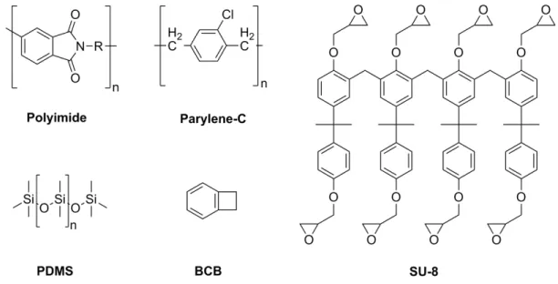
Several research groups have attempted to investigate the effects of mechanical mismatch between the microelectrodes and the cortical tissue. Many groups have developed microelectrode substrates and substrate coatings from materials such as poly(imides), benzocyclobutene (BCB), SU-8, polydimethylsiloxane (PDMS), and Parylene-C (Figure
1-3) that are more compliant than materials traditionally used to create electrodes.50-57 For example, Rousche et al. reported the fabrication of poly(imide)-based multichannel implantable intracortical electrodes and recorded the neural activity from the cortex of rat’s brain.58 Polyimide presents several attractive features such as inherent flexibility, and manufacturability using existing microfabrication technology. However, due to its low stiffness (in comparison to metal- or silicon-based microelectrodes), polyimide-based electrodes of typical dimensions cannot penetrate through the tissue during surgery (i.e., IF > 𝐹!" ), resulting in device buckling. Another problem in the use of polyimide for neuroprosthetic devices is the high moisture uptake (4-6% w/w), which can lead to a rapid decrease of the electrode impedance after implantation.
Figure 1-3. Chemical structures of compliant polymeric materials and monomers commonly used for neural interfaces.
To address some of the challenges associated with the use of polyimides, Lee et al. reported a new design for polyimide-based intracortical microelectrodes, which provide adequate stiffness for insertion into neural tissue.59, 60 In their design, a 5-10 µm thick silicon layer was applied to the polymer to increase the composite stiffness to prevent buckling during insertion. The Young’s modulus of these electrodes increased
significantly from 2.8 GPa (neat polyimide without silicon backbone) to 31 GPa and 58 GPa with 5 and 10 µm thick silicon layers, respectively. A penetration test into rat brains showed that the electrodes with silicon backbone layers could penetrate the rat pia without buckling. In vitro biocompatibility tests revealed no cytotoxic effects on cultured cells and supported cell adhesion and growth over the polyimide electrode surface. However, one of the initial goals for the design of polyimide-based microelectrodes was to facilitate a “softer” implant after insertion. The intent was to minimize strain field generations within the surrounding “soft” brain tissue. The use of a “stiff” silicon backing to increase the polyimide devices from 2.8 GPa to 31 or 58 GPa (defined above) prevents buckling failure during insertion, yet appears counterproductive towards minimizing chronic in vivo tissue strain.
Alternative work on flexible polymer-based intracortical electrodes included the use of benzocyclobutene (BCB)-based polymers as a template for chronic neural applications.
61-63 BCB polymers offer a lower moisture uptake (0.2% w/w) than polyimide (4-6% w/w),
good chemical resistance, and also a low dielectric constant (~2.6). BCB polymers display a stiffness which is comparable to that of polyimides, and therefore buckling during insertion is also an issue for this type of polymer. Thus, reinforcing strategies have been developed to increase the stiffness of BCB-based neural interfaces to enable insertion into neural tissue. For example, Lee et al. micro-machined a thin layer of silicon backing (5-10 µm) onto the electrode.63, 64 Clement et al.62 succeeded in recording neural signals in a rat cortex using BCB-based electrodes without the problem of water uptake that occurs with polyimide-based electrodes as mentioned above. However, the silicon-backed BCB microelectrode possesses similar concerns for increase tissue strain described above for polyimide-based devices. Either tissue strain does not directly impact recording quality, or the reported study was not carried out long enough to realize the strain-induced detriments to the neuroinflammatory response. To this end, an alternative approach is the use of dissolvable materials such as glucose or sugar.65 Therefore, BCB-based electrodes may have the potential for further development of long-term compliant neural implants.
Parylene-C is another compliant polymer with low water absorption and low dielectric constant. While both polyimide and parylene have comparable elastic moduli, Parylene-C has several advantages such as easy fabrication, and lower water absorption than polyimide. However, it has a low tensile strength, and is also suffering from buckling during insertion.46 Nevertheless, several studies have reported the development of Parylene-C based microelectrodes that can be inserted into the brain tissue without assistive aids. For example, the LaPlaca lab fabricated flexible Parylene-C based electrodes using photolithography techniques that were inserted into the rat barrel cortex.46 LaPlaca was interested in determining the extent and duration that a controlled cortical impact and device micromotion effects on both the integrity of the microelectrode, and the ability to obtain neural recordings. To facilitate insertion of the “flexible” Parylene-C devices, implants were designed larger, at 100 µm wide and 25 µm thick. LaPlaca and colleagues demonstrated that the “flexible” devices withstood the trauma and associated micromotion, and remained capable of obtaining neural recordings minutes after impact, suggesting future applicability of such devices. While promising, the histological effects of the larger implant size may negatively affect chronic recording abilities. In an attempt to better understand how modifications to traditional microelectrode geometries could facility insertion of flexible polymer microelectrodes, Egert et al. engineered parylene-based microelectrodes with a variety of shank footprints.44 In their brief conference proceedings, the team reported on the application of the addition of vertical stiffeners, alternative geometries, and insertion guides designed to remain attached throughout the life of the implant or be removed either directly after implantation of slowly through bio-degradation. Each of the novel devices tested remained electrically active after 3 months of a soak test. Unfortunately, design strategies that facilitate insertion and were capable of integration into array technology required permanent features that either increased the stiffness or footprint, both which have been linked to increased neuroinflammatory responses. Therefore, while Parylene-C microelectrodes have been developed for acute in vivo and chronic cell-free recording, long-term reliability of “flexible” non-reinforced devices has to our knowledge yet to be