HAL Id: hal-01359519
https://hal.archives-ouvertes.fr/hal-01359519
Submitted on 2 Sep 2016
HAL is a multi-disciplinary open access
archive for the deposit and dissemination of
sci-entific research documents, whether they are
pub-lished or not. The documents may come from
teaching and research institutions in France or
abroad, or from public or private research centers.
L’archive ouverte pluridisciplinaire HAL, est
destinée au dépôt et à la diffusion de documents
scientifiques de niveau recherche, publiés ou non,
émanant des établissements d’enseignement et de
recherche français ou étrangers, des laboratoires
publics ou privés.
Coupled optoelectronic oscillators: design and
performance comparison at 10 GHz and 30 GHz
Vincent Auroux, Arnaud Fernandez, Olivier Llopis, P Beaure D ’Augères, A
Vouzellaud
To cite this version:
Vincent Auroux, Arnaud Fernandez, Olivier Llopis, P Beaure D ’Augères, A Vouzellaud. Coupled
optoelectronic oscillators: design and performance comparison at 10 GHz and 30 GHz. 2016 IEEE
International Frequency Control Symposium, May 2016, New Orleans, United States. pp.373-376.
�hal-01359519�
Coupled optoelectronic oscillators: design and
performance comparison at 10 GHz and 30 GHz
V. Auroux
1,2, A. Fernandez
1,3, O. Llopis
11 CNRS, LAAS, Univ. de Toulouse, France 3 Univ. de Toulouse, UPS, LAAS, Toulouse, France
7 avenue du Colonel Roche ; BP 54200 ; 31031 Toulouse, France
P. Beaure d’Augères
2, A. Vouzellaud
22 OSAT
16 avenue Didier Daurat, Toulouse, France
Abstract—Two SOA-based coupled optoelectronic oscillators (COEO) at 30 GHz and 10 GHz have been studied. These systems have been designed thanks to a preliminary study of the noise of various optical amplifiers (SOA and EDFA). The COEOs measured single sideband phase noise level is −132 dBc/Hz and −125 dBc/Hz at 10 kHz offset from 10 GHz and 30 GHz respectively. The architecture proposed enabled a rejection of spurious modes above 70 dB.
Keywords— microwave oscillator; optoelectronic oscillator; COEO; microwave photonics; phase noise; optical amplifiers; EDFA; SOA.
I. INTRODUCTION
The important rise of telecommunication systems in the past decades has increased the necessity for high spectral purity frequency references at high frequencies. Besides, the saturation of X-band motivated the search of frequency references at upper frequencies, such as K-band. Potential applications could be found in radar detection [1] or terrestrial-satellite communications. Frequency multiplication from highly stable sources, such as quartz sources, is limited by the increase of the noise floor, which is often prohibitive at millimetre wave frequencies. On the contrary, microwave generation using optics becomes a very efficient technique in this frequency range. Indeed, passive optical resonators or delay lines present a high Q factor which can be used to stabilise the microwave frequency. The best phase noise performance at 10 GHz has been achieved using a 16 km delay line [2]. However, spurious oscillation modes are very close to the carrier in this type of OEO, particularly if a very long delay line is used. Even if an efficient spurious modes rejection technique is implemented, these parasitics signals remain a real problem for applications (such as radar applications). An alternative to these long delay lines oscillators is to use an optical resonator. In this case, the free spectral range will be larger and the spurious peaks will be shifted towards higher frequencies. Also, the system will gain in compactness. In this case however, the laser must be locked to the resonator. This last difficulty disappears if an active optical resonator is used, with sufficient gain to start an optical oscillation. The first architecture of this type has been proposed in the 1990’s [3]. In this system, a mode-locked laser is coupled to a microwave oscillator (COEO)[4].
In a COEO, the optical amplifier is the active element of the optical part of the system, and thus may contribute
largely to the output RF phase noise. Although RF amplifiers phase noise properties are well known, there is much less published data on the RF phase noise induced by optical amplifiers. Therefore, our first goal has been to compare various types of optical amplifiers (semiconductor and fiber amplifiers) for this application. Then, two COEO have been realized, one at 10 GHz and another one at 30 GHz, and their performances are compared and discussed in this paper.
II. RFPHASE NOISE PROPERTIES OF SOA AND EDFA
Mode locked lasers need a high optical saturation power amplifier to generate a broad frequency comb. Hence, residual phase noise measurements are performed on a booster semiconductor optical amplifier (SOA) and an erbium doped fiber amplifier (EDFA) which both present a high small signal gain and a relatively high optical saturation power, as reported on TABLE I.
TABLEI. OPTICAL PORPERTIES OF AMPLIFIERS STUDIED
Property Optical Amplifier
SOA EDFA
Small Signal Gain 28 dB 33 dB
Optical saturation power 16 dBm 20 dBm A. Experimental Setup
Residual phase noise measurements were carried out on an optical link using successively the two different optical amplifiers, the other elements of the link being unchanged. The measurement setup is depicted in Fig. 1 and is detailed in[5]. A 3.5 GHz low phase noise and low amplitude noise dielectric resonator oscillator (DRO), together with and a cross correlation phase detection technique, have been used. A delay on the RF path has also been adjusted to correspond to the delay introduced by the optical link, in order to cancel a possible parasitic detection of the DRO phase noise.
Fig. 1 : Experimental setup for residual phase noise measurements of an optical link at 3.5 GHz
B. Amplifiers residual phase noise performances
Both saturated and unsaturated conditions were investigated for each optical amplifier. High saturation of optical amplifiers enables to increase the carrier-to-noise ratio (CNR) and hence to decrease the phase noise floor up to 15 dB for the EDFA and up to 10 dB for the SOA. Besides RF phase noise characterization, baseband amplitude noise measurements have been carried out. A strong correlation between amplitude noise and RF phase noise is observed, possibly due to amplitude to RF phase conversion at the photodiode level. A method to reduce this conversion process has already been proposed in [6] and has been applied for all our phase noise measurements. By adjusting optical power on the photodiode, we obtained a reduction of 15 dB on the phase noise close to the carrier for the EDFA as shown in Fig. 2. However, no such reduction is observed for the SOA, suggesting another conversion process in the amplifier itself.
Fig. 2 : 3.5 GHz residual phase noise measurements of an EDFA in saturated regime with and without cancellation of amplitude to phase noise conversion process on the photodiode
Residual phase noise measurements for both saturated amplifiers are reported inFig. 3. As EDFA presents a low noise figure, EDFA phase noise floor is 12 dB lower than that of the SOA. However, an important rise of 1/f noise close to the carrier is observed for the EDFA. Thus, there is a tradeoff whether the phase noise performance has to be obtained close or far from the carrier [7]. In this work, COEO are based on SOA, due to integration capacity as well as good close to the carrier phase noise performance requirements.
Fig. 3 : Residual phase noise measurements at 3.5 GHz of EDFA and SOA under saturation regime
III. COUPLED OPTOELECTRONIC OSCILLATORS A. Architecture and characteristics of COEO
Fig. 4 : Topology of 300 m long COEO realized at 10.2 GHz and 30 GHz
The architecture used for the two COEO is depicted in Fig. 4. The design is similar to regenerative mode locked lasers [8] but presents one optical output with a pulse train and another RF output with a stable signal at 10 GHz or 30 GHz. The active optical resonator is a mode locked laser composed of an SOA, a 35 GHz bandwidth Mach Zehnder intensity modulator (MZM), a fiber delay to increase the optical cavity quality factor and a polarizer. The total length of the cavity is 300 m approximately. The pulse train circulating in the mode locked laser is extracted with a 50/50 coupler and delayed by a 100 m fiber spool before the 70 GHz bandwidth photodiode. The RF beat note generated by the frequency comb on the photodiode is filtered (with a dielectric resonator), amplified and sent back to the modulator. Finally, optoelectronic and optical oscillations are synchronized thanks to an RF phase shifter.
The COEO performances depend on the quality factor of the optical resonator. In order to estimate the COEO RF Q factor, a measurement of the frequency shift ∆ induced by a known RF phase shift ∆ has been carried out[4]. The phase shifter has been first calibrated using a vector network analyzer (VNA), and then the frequency shift ∆ is measured
on an electrical spectrum analyser. The COEO quality factor is then computed using:
∆
2 ∙ ∆ with being the RF oscillation frequency.
The RF quality factor obtained, at 10.2 GHz is 1.9 106. The
equivalent optical quality factor is then 3.5 1010. Mode
locked lasers provide very high quality factor resonators which are necessary to reach high spectral purity at high frequencies. For comparison, the dielectric resonators used as RF filters in the optoelectronic loop feature a quality factor of 2500 for the 10 GHz one and 600 for the 30 GHz one.
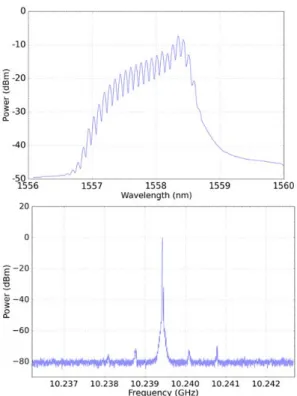
The RF and optical spectra of the 10 GHz COEO and the 30 GHz COEO are reported in Fig. 5 and Fig. 6 respectively. The extra cavity fiber spool increases the delay in the optoelectronic loop and thus enables a filtering of the spurious modes thanks to the Vernier effect. In both cases, side mode suppression above 70 dB is observed, superior than any conventional delay line OEO, to our knowledge. Besides, the optical spectrum corresponding to the 10 GHz pulse train is strongly affected by the SOA nonlinearities in saturation regime [9]. These nonlinearities have a major impact on the pulse train distortion, and also on the red shift that is observed on the optical spectrum. The dispersion management in the cavity is of great importance in order to broaden the spectrum.
Fig. 5 : RF signal (bottom) and optical spectrum (up) for the 10.2 GHz COEO
Fig. 6 : RF signal (bottom) and optical spectrum (up) for the 30 GHz COEO
B. Comparison between 10 GHz and 30 GHz COEO
Phase noise measurements have been performed with the signal source analyser Agilent E5052B and a microwave downconverter E5053A. At 30 GHz, external harmonic mixers have been used. The phase noise measured for both COEO using a correlation factor of 100 is reported in Fig. 7.
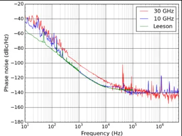
The two oscillators feature a very low phase noise, reaching −132 dBc/Hz and −126 dBc/Hz at 10 kHz from 10 GHz and 30 GHz respectively. At 10.2 GHz, a second filtering effect occurs at 30 kHz from the carrier due to the system dynamic (synchronization of the oscillations). Since the phase noise of optoelectronic oscillators is mainly limited by the active elements in the system, we have evaluated the phase noise contribution of all these elements. The total closed loop phase noise contribution is computed from the residual phase noise contribution of each active device through the Leeson model approach [10]:
10 ∙ log
8 ∙ ∙ 1 ∙
where is the oscillation frequency (10.2 GHz), is the RF quality factor, the offset frequency and is the total phase noise due to the amplifiers (RF and optical).
The oscillator phase noise obtained with this model is also reported in Fig. 7 for the 10 GHz COEO. In this plot, the Q factor is adjusted in order to fit the measurement data for the 1/f noise. This later Q factor is somewhat lower than the
one obtained from the small perturbation experiment (paragraph III.A) and this discrepancy is still not well understood. However, the goal was to understand the different noise contributions to the spectrum, and this analysis is still possible.
Between 10 Hz and 200 Hz, the COEO is not limited by the amplifiers phase noise: a vibration noise seems to dominate the phase noise in this frequency range. One can note that the system is not working on an optical table and that no special efforts have been made to protect the fiber spools from vibrations. Further studies on vibrations impact on fiber spools are ongoing. Between 200 Hz and 10 kHz, the phase noise of the system is limited by active elements of the loop, especially the optical amplifier. Hence, intra-cavity loss reduction is important in order to saturate the optical amplifier and then lower its phase noise. Far from the carrier, the phase noise floor at −140 dBc/Hz is fixed by the carrier to noise ratio.
The phase noise spectrum of the 30 GHz COEO features a similar shape, excepted for the filtering effect at 30 kHz from the carrier. However, in the case of this oscillator, the phase noise measurements above this frequency offset are too close from the measurement bench noise floor and cannot be discussed (at 30 GHz, the signal to noise ratio at the E5052B input is degraded because of the conversion losses of the harmonic mixers).
Fig. 7 : Phase noise of two SOA-based COEO at 10.2 GHz and 30 GHz
Finally, the phase noise of the 30 GHz COEO is a little lower than the phase noise which could be obtained using the 10 GHz COEO multiplied in frequency by 3 (frequency multiplication would increase the phase noise of 9.5 dB). However a better performance was expected for this millimeter wave COEO because, contrarily to conventional microwave sources, the Q factor in OEOs increases when the RF frequency increases. A more detailed study of the noise contributions in the 30 GHz COEO is on-going. We may already guess that the 30 GHz RF amplifier is noisier than the 10 GHz one, and probably also that the AM to RF phase conversion at the photodiode level is stronger.
IV. CONCLUSION
Residual phase noise measurements have been performed on two different optical amplifiers (SOA and EDFA). Although the EDFA features a lower phase noise floor thanks to a better noise figure, the SOA has been chosen because it features a lower phase noise contribution close to the carrier. Thus, two SOA-based COEO at 10.2 GHz and 30 GHz have been realized. Both COEO are low phase noise sources, reaching −132 dBc/Hz and −126 dBc/Hz at 10 kHz offset from 10 GHz and 30 GHz respectively. The performance obtained with the 30 GHz source is a little better than what could be obtained with the normal frequency multiplication rule from the 10 GHz one, and still probably can be improved.
REFERENCES
[1] I. Gresham, A. Jenkins, R. Egri, C. Eswarappa, N. Kinayman, N. Jain, R. Anderson, F. Kolak, R. Wohlert, S. P. Bawell, et others, « Ultra-wideband radar sensors for short-range vehicular applications », Microw. Theory Tech. IEEE Trans. On, vol. 52, no 9,
p. 2105–2122, 2004.
[2] D. Eliyahu, D. Seidel, et L. Maleki, « Phase noise of a high performance OEO and an ultra low noise floor cross-correlation microwave photonic homodyne system », in Frequency Control
Symposium, 2008 IEEE International, 2008, p. 811‑814.
[3] X. S. Yao et L. Maleki, « Dual microwave and optical oscillator »,
Opt. Lett., vol. 22, no 24, p. 1867–1869, 1997.
[4] N. Yu, E. Salik, et L. Maleki, « Ultralow-noise mode-locked laser with coupled optoelectronic oscillator configuration », Opt. Lett., vol. 30, no 10, p. 1231‑1233, mai 2005.
[5] G. Cibiel, M. Régis, E. Tournier, et O. Llopis, « AM noise impact on low level phase noise measurements », Ultrason. Ferroelectr. Freq.
Control IEEE Trans. On, vol. 49, no 6, p. 784–788, 2002.
[6] Z. Abdallah, A. Rumeau, J. Maxin, A. Fernandez, L. Morvan, O. Llopis, et G. Cibiel, « Photodiode nonlinear modeling and its impact on optical links phase noise », Proc. of EFTF, Neuchatel, June 2014. [7] V. Auroux, A. Fernandez, O. Llopis, P.-H. Merrer, A. Vouzelaud, et
others, « Microwave phase noise properties of optical links involving small signal and gain saturated optical amplifiers », in European
Frequency and Time Forum (EFTF), Neuchatel, June 2014.
[8] G. R. Huggett, « Mode-locking of CW lasers by regenerative RF feedback », Appl. Phys. Lett., vol. 13, no 5, p. 186–187, 1968.
[9] G. P. Agrawal et N. A. Olsson, « Self-phase modulation and spectral broadening of optical pulses in semiconductor laser amplifiers »,
Quantum Electron. IEEE J. Of, vol. 25, no 11, p. 2297–2306, 1989.
[10] D. B. Leeson, « A simple model of feedback oscillator noise spectrum », Proc. IEEE, vol. 54, no 2, p. 329–330, 1966.