HAL Id: hal-03240765
https://hal.archives-ouvertes.fr/hal-03240765
Submitted on 28 May 2021
HAL is a multi-disciplinary open access
archive for the deposit and dissemination of
sci-entific research documents, whether they are
pub-lished or not. The documents may come from
teaching and research institutions in France or
abroad, or from public or private research centers.
L’archive ouverte pluridisciplinaire HAL, est
destinée au dépôt et à la diffusion de documents
scientifiques de niveau recherche, publiés ou non,
émanant des établissements d’enseignement et de
recherche français ou étrangers, des laboratoires
publics ou privés.
Association of recycled PC PSU with MPPT and a
control application in a smartphone
Thien-Minh Nguyen, Quoc Dung Phan, Pascal Maussion
To cite this version:
Thien-Minh Nguyen, Quoc Dung Phan, Pascal Maussion. Association of recycled PC PSU with
MPPT and a control application in a smartphone. IECON 2020, Oct 2020, Singapore, Singapore.
pp.0, �10.1109/IECON43393.2020.9254905�. �hal-03240765�
OATAO is an open access repository that collects the work of Toulouse
researchers and makes it freely available over the web where possible
Any correspondence concerning this service should be sent
to the repository administrator:
tech-oatao@listes-diff.inp-toulouse.fr
This is an author’s version published in:
https://oatao.univ-toulouse.fr/2
7208
To cite this version:
Nguyen, Thien-Minh and Phan Quoc, Dung and Maussion, Pascal Association of recycled PC PSU with MPPT and a control application in a smartphone. (2020) In: IECON 2020, 18 October 2020 - 21 October 2020 (Singapore, Singapore).
Official URL:
https://doi.org/10.1109/IECON43393.2020.9254905
Open Archive Toulouse Archive Ouverte
Association of Recycled PC PSU with MPPT
and a Control Application in a Smartphone
Minh Thien Nguyen 1, Quoc Dung Phan 1
1
Power Electronics Research LAB, Faculty of Electronic and Electrical Engineering, Ho Chi Minh City University of Technology (HCMUT),
Vietnam National University (VNU-HCM),
268, rue de Ly Thuong Kiet, 10th Dist., BP 70000 Ho Chi Minh City, Vietnam pqdung@hcmut.edu.vn
Pascal Maussion 2
2
Control and Diagnostic of Electrical Sytems Group LAPLACE, Université de Toulouse, CNRS, INPT, UPS, France
2, rue Charles Camichel - BP 7122 - 31071 Toulouse cedex 7
pascal.maussion@laplace.univ-tlse.fr
Abstract_ This paper studies some original solutions for
rural electrification based on re-used components according to the frugal innovation concept. Several associations of recycled PSUs from PCs, for an hybrid renewable energy system (PV and hydro) are presented and investigated. The objective is to increase the system power by associating several units. These power supply’s converters can be controlled as battery chargers and supervised by MPPT algorithms implemented in an Arduino microcontroller. The different configurations for serial/parallel associations of the inputs or the outputs are investigated in terms of feasibility, robustness, and performance trough simulation and experimental results. Moreover, the settings of the whole system are given to the microcontroller by an application implemented in an Android smartphone.
Keywords— PSU, Second-life Application, MPPT, Solar energy, smartphone, frugal innovation, PV
I. INTRODUCTION
The recent development of small hydropower applications together with a photovoltaic generator is an interesting solution for the exploitation of natural energy sources, with relatively easy production and processing. The global system includes a pico hydro unit of hundreds of W or kW (with a recycled induction machine), hybridized by a photovoltaic generator with energy storage in car recycled batteries. Conversion of the solar energy is achieved thanks to PSU recycled from discarded PCs according to the frugal innovation principles. The whole is designed to supply some home appliances (lighting, refrigerators, TV, radio, etc) of several houses in a village located in an off-grid remote area. Since most PSUs are compliant with ATX motherboard design, many common features can be found throughout different models and manufacturers, which is a great advantage. Total power requirements for a personal computer may range from 150 W to more than 700 W for a high-performance computer with multiple graphics cards. Nevertheless, PSUs are commonly found with a power rating between 300W to 500W. The 375W ATX power supplies, Dell L375P-00, has been selected for the study of its modification and transformation processes for the second-life usage in a photovoltaic generation system. The power supply’s block diagram is featured in Fig. 1. Most power supplies follow the same general block diagram [1]. The main power stage of Dell L375P-00 PSU is a single-switch forward converter with RCD reset scheme and a power transformer with the ratio (TR) is 40:6.5. The PWM controller of the forward converter is the UC3843 current-mode IC.
An alternative to dismantling and recycling has been studied by the same research team in [1] [2]. The main idea in these works is to transform a part of an ATX power supply, the active PFC front-end stage, into a new converter dedicated to MPPT control for PV convertion but this needs a new PCB. Besides, [3] reuses the whole PC power supply with only few light modifications on the existing PCB, according to the frugal innovation principles.
II. TRANSFORM AN ATX POWER SUPPLY UNIT (PSU)
INTO AN MPPT CONTROL CONVERTER FOR A PHOTOVOLTAIC GENERATION
A. Transform a Dell L375P-00 PSU into an MPPT control converter
The main function of PSU is to create fixed DC power for the PC. And this function is not possible to apply directly to the renewable power system for lower voltage input. Some part of the PSU is adjusted to meet the requirements of the input voltage level and the output voltage is controllable.
Fig. 1. Common block diagram of power supply 1) Gain control of PSU by removing the control IC
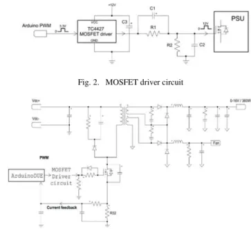
When UC3843 is removed, feedback circuits from the output side of the PSU as well as WT7515's protection function are automatically disabled, thereby enabling the converter to operate independently of PSU constraints without any more modification. After removing UC3843, the PWM control signal of the converter is now provided by Arduino, the MPPT controller with P&O and INC algorithm implemented based on the previous study[1]. However, the voltage rating of Arduino DUE is 3.3V, not enough to control the power MOSFET [4]. Therefore, a TC4427 MOSFET [5] driver circuit is used which is shown in Fig. 2 and 3.
2) PV current and voltage feedback for MPPT control
The input current is converted to a feedback voltage signal from an onboard Rshunt after the power MOSFET. The networks of resistors and Zener diodes serve as sensing
circuits that convert an input voltage into voltage signals that can be read by analog input pins of Arduino and its over-voltage protection.
3) Modification of L375P-00 output
Modification focuses on 12V output port because provides the highest power (360W over 375W of the LP375-00 power supply). This PSU has 2 outputs 12V_A/18A and 12V_B / 18A. Each output is 216W maximum. These 2 outputs of 12V_A and 12V_B are from the same source, so it is possible to pair them to get the maximum power (360W). Removing the other outputs is necessary to avoid power losses in the inductors, resistors, and other unwanted effects.
Fig. 2. MOSFET driver circuit
Fig. 3. L375P-00 circuit diagram after modification 4) Control software on Smartphones
Arduino microcontroller is connected to a Bluetooth module to perform communication with the smartphone. The system communication network shown in Fig. 4 was based on a previous study Erreur ! Source du renvoi
introuvable.. It includes a real-time data transfer function (I, V, P of PV panel) and MPPT operation control: manual set the duty cycle of the PWM control signal, select the MPPT control algorithm between P&O and INC, enable or disable MPPT control. The function of controlling the duty-cycle test will be disabled during the MPPT control to avoid trouble affecting the efficiency of the control.
Fig. 4. System communication network
III. EMULATED PV PANEL
Perform the test of the modified PSU when operating with a PV panel is indispensable, so simulating a circuit with corresponding P-V characteristics is necessary and inexpensive, suitable for testing in the environment of the laboratory (with no sunlight). P-V characteristics of solar panels are emulated with a DC source and a resistor connected in series [6], shown in Fig.5. When changing the duty cycle of PSU, their output P-V characteristics will have almost the same form as compared to the P-V panels. An experiment was performed by manually changing the duty cycle of the PSU and observing the change in voltage, current, and power obtained with the parameters given in TABLE I.
IV. EXPERIMENTI–MPPT CONTROL WITH ONE PSU
A. MPPT control testing
The performance of MPPT control is tested with the change of load (Rout) and input power (by changing R). The results are shown in Fig. 5, where the maximum power is achieved at a duty cycle equal to 0.34, corresponding to the theory. Results are given with 4 cases, corresponding to 2 loads and 2 input power using P&O and INC algorithm. Fixed parameters are given in TABLE I.
The theoretical values when reaching MPP:
•PWM duty cycle: %
•PSU input voltage: 0.5
•PSU input current: ! "
•PSU power input: # $
Table III compares theoretical values and measured values by voltmeters, oscilloscope, and feedback values are shown on the smartphone control application. The theoretical value of when reaching MPP is 140V and the actual at the maximum power point falls into the 130V range.
Fig. 5. Solar panels emulation B. Dynamic MPPT control testing
The experiment was performed by starting the MPPT control and changing the load and input power similar to the above 4 cases. The power value is displayed by Arduino's Serial Plotter. The process is shown in Fig. 6 where experimental results are similar to the theoretical ones.
TABLE I.
EMULATEDPVPANELEXPERIMENTALPARAMETERS R = 100 Ω
Vdc= 280 V Rout= 0.33 Ω fPWM = 118 kHz
TR = 40 : 6.45
% %0.33100 6.45 0.3640 TABLE II. MPPTEXPERIMENTALPARAMETERS Vdc = 280 V fPWM = 118 kHz TR = 40 : 6.45
∆ 0.01 (step change of the duty cycle) Ta = 50 ms (sampling period)
Fig. 6. Experiment I – Dynamic MPPT control when load and input power changes TABLE III.
EXPERIMENT I–COMPARISON TABLE OF MEASURED AND FEEDBACK VALUES
Parameters 1: R = 100 Ω R,-. = 0.33 Ω
Theoretical Measured Feedback
Vpv (V) 140 132 131 Ipv (A) 1.4 1.374 1.400 Ppv (W) 196 181 183 Duty (%) 35 35.9 N/A Parameters 2: R = 100 Ω R,-. = 0.83 Ω
Values Theoretical Measured Feedback
Vpv (V) 140 131 130 Ipv (A) 1.4 1.371 1.390 Ppv (W) 196 179 180 Duty (%) 56 52.7 N/A Parameters 3: R = 206 Ω R,-. = 0.33 Ω
Values Theoretical Measured Feedback
Vpv (V) 140 133 132 Ipv (A) 0.68 0.65 0.69 Ppv (W) 95 86 91 Duty (%) 24.6 24.9 N/A Parameters 4: R = 206 Ω R,-. = 0.83 Ω
Values Theoretical Measured Feedback
Vpv (V) 140 122 120
Ipv (A) 0.68 0.753 0.792
Ppv (W) 95 91 95
Duty (%) 24.6 24.9 N/A
V. PSUS ASSOCIATION
The structure of a PSU is modeled under PSIM with the L375P-00 parameters.
A. Connection types
The PSUs are connected to increase the overall system power and to raise the voltage to reduce transmission losses is also considered. There are several possible input/output connection structures to be considered below: Parallel (P), Serial (S), Serial connected (Sc), Separated (Sp). Each input/output configuration is considered for MPPT control.
1) Parallel input/output
When a PSU performs MPPT control, its input DC voltage will change. As 2 PSU share the same input voltage they cannot be separately controlled by their own MPPT. Then, the parallel input/output connection can’t be used.
2) Serial input/output a) Advantages
• No need for an additional circuit to drive the PSUs.
• High input voltage will reduce transmission loss.
b) Disadvantages
• As the PSU shares the same input voltage they cannot be separately controlled by their own MPPT.
• An additional interface circuit is needed as the two PSUs do not have the same ground.
• Need to isolate the PSU’s case to avoid short circuit.
• An inactive PSU will affect the whole system. Consequently, only the serial input connected can be used.
3) Serial connected input/output
Fig 7 and 8 show the different possibilities for the inputs and outputs with the middle connection which changes the conclusions related to the serial connection.
Fig. 7. Serial connected input
Fig. 8. Serial connected output a) Advantages
• Sc connection is used to overcome the disadvantages of the serial connection. With the MPPT, the input voltage of each PSU can change independently without affecting the input voltage of the others.
• High input voltage will reduce transmission loss.
• When there is an inactive PSU, the remaining PSUs network will auto-adapt to keep the MPPT working.
b) Disadvantages
• An additional interface circuit is needed as the two PSUs do not have the same ground.
• Need for a PSU’s case insulation to avoid short circuit.
Based on the above result, Serial Connected input, Serial output connection can be used.
4) Separated input/output
Each PSU will be connected to a PV separately. The separate output connection is not suitable for a battery bank so it will not be considered.
B. Possible connections
Based on the configurations reviewed, 4 combinations of input-output can be used for connecting PSUs:
1. Serial connected – Serial (Sc - S) 2. Serial connected – Serial connected (Sc - Sc) 3. Separated – Serial (Sp - S)
4. Separated – Serial connected (Sp - Sc)
C. PSIM model with Emulated PV panel
This section simulates some possible combinations of the emulated PV panels with the PV panel characteristics. The results of the 3 combinations is given when pairing 2 PSUs, with the same parameters or different transformer ratios, different inductors, in the objective of a robustness study. Circuit diagram and simulation results for the Sp-S config. are summarized in Fig. 11 and 12 as an example.
D. PSIM model with PSIM Solar module.
In this section, the simulations are performed with the same 2 PSUs connected to and powered by 2 Solar modules. Simulations include changes in the power of a solar module (corresponding to shading) and load changes. PV panels parameters shown in Table IV are set, based on the pairing of the FVG10P solar module Erreur ! Source du renvoi
introuvable.. Configurations and simulation results are summarized in Fig. 11 to 14.
TABLE IV.
PSIMSOLAR MODULE PARAMETERS
PSIM Solar Module
Characteristics PV full PV 50% shaded Open Circuit Voltage Voc (V) 126 126
Short Circuit Current Isc (A) 3.96 1 98 Maximum Power Voltage Vm (W) 105 105 Maximum Power Current Im (A) 3.42 1.71 E. Partial conclusion
The simulations show that the emulated PV panel can be used to test the system operation in response to the actual change of PV panel characteristics. When pairing 2 PSUs with similar parameters, the Sp-Sc and Sp-S configurations give the best and similar results. However with 2 different PSUs and when simulating with the PV panel module, Sp-Sc gives the best results regarding stability and power efficiency.
Fig. 9. Emulated PV panel: Sp – S connection
Fig. 10. Emulated PV panel: Sp – S results
Fig. 12. PSIM Solar module: Sp – S results
Fig. 13. PSIM Solar module: Sp– Sc connection
Fig. 14. PSIM Solar module: Sp – Sc results
VI. EXPERIMENT-COMBINATIONOFPSUS
The experiments were performed with 2 DELL L37500 PSU; 2 power supplies + resistors; Microcontroller Arduino
DUE; DC power supply- MOSFET control circuit; load; Yokogawa WT1800 Power analyzer, cf Fig.15.
Fig. 15. Experimental working area
In this experiment, the separate input configuration (Sp) will be used due to its highest efficiency and ease of installation, as well as being able to control multiple PSUs from an Arduino without the need for another controller circuit (compared to the serial input configuration-S).
A. Separated inputs – Serial connected outputs (Sp-Sc)
PV panels are simulated with the parameters shown in Table IV. Fig. 17 to 18 show SP-Sc configuration with 2 PSUs the voltage, current, power waveforms, and the related efficiency of each PSU, along with the efficiency of the entire system thanks to the INC algorithm. The results are similar to that of the P&O algorithm. The duty cycle of the two PSUs reach the optimal value for the maximum power of each PSU, around 100W which corresponds to the theoretical value, indicating that the MPPT control works effectively. The efficiency of each PSU and the whole system is about 83% - 84% with Rload = 1Ω, when overloading or small load will reduce the performance of the PSU.
Fig. 16. Experiment I – Sp-Sc connection Circuit and Parameters
Fig. 18. Experiment I – Sp-Sc connection result B. Separated inputs – Serial outputs (Sp-S)
The configuration, waveforms, and experimental results for the Sp-S model are shown in Fig. 19 to Fig. 21. They are similar to the that of Sp-Sc model (same parameters) and match with simulation results).
Fig. 19. Experiment II – Sp-S connection Circuit and Parameters
Fig. 20. Experiment II– Sp-S connection PWM
Fig. 21. Experiment II – Sp-S connection result
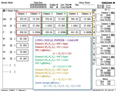
VII. EXPERIMENTIII– ABOVE 1KW
This part experiences the combination of 3 PSUs to increase the total power above 1kW. Both P&O and INC algorithms give the same MPPT results. Fig. 22 shows the experimental circuit while Fig. 23 provides the results of the system with the P&O control algorithm.
Fig. 22. Experiment III – 3 PSUs with Sp-S connection circuit
Fig. 23. Experiment III – 3 PSUs with Sp-S connection results
VIII. CONCLUSION
Based on the frugal innovation principles, this paper has presented original associations of recycled PC power supply units (PSU) that can be used as battery charge controllers in some energy production systems dedicated to rural electrification. For a very affordable price, they can be dedicated to some remote areas in some developing countries. This will help them to reach their renewable energy developing plans. The voltage output of the PSU can be modulated up to 16V, the max power of each Dell L375P-00 model is 360W. Simulation and experimental results of their association with MPPT control show that several PSU’s can be paired to increase the system power above 1 kW. Different options are described, the best solutions are listed.
MPPT control of the PSU’s is implemented inside an Arduino DUE microcontroller which has 12 ADC pins and 12 PWM outputs, able to control up to 6 PSU at the same time (each PSU requires 2 ADC pins and 1 PWM output),
with open source code, no expensive sensors and with a minimal cost. Monitoring and control applications can be used with commonly used Android smartphones. Future work will deal with power increase (several kW), diagnostic of the possible failures when serval PSUs are associated.
REFERENCES
[1] S A Abuzed; C-W Tsang; M P Foster; D A Stone “Repurposing ATX power supply for battery charging applications”, 8th IET International Conference on Power Electronics, Machines and Drives, 2016, pp 1–5
[2] D. Rogers ; J. E. Green ; M. P. Foster ; D. A. Stone ; D. Schofield ; A. Buckley ; S. Abuzed, “ATX power supply derived MPPT converter for cell phone charging applications in the developing world”, 7th IET International Conference on Power Electronics, Machines and Drives, PEMD 2014
[3] B. Kim, L. Bun, M. Pietrzak-David and P. Maussion, B. Dagues, C. Azzaro-Pantel, “Second Life of Power Supply Unit As Charge Controller in PV System And Environmental Benefit Assessment”, Industrial Electronics Conference, IEEE-IECON 2016
[4] Fairchild Semiconductor, “FQA11N90 900V N-Channel MOSFET” [5] Microchip, “TC4426/TC4427/TC4428 1.5A Dual High-Speed Power
MOSFET Drivers”
[6] T.C. Le, A. Carlier, P. Maussion, PQ. Dung, “Measuring rotor speed with a smartphone camera”, IEEE Industrial Electronics CONference, IECON 2017, October, Beijing, China,
[7] Huu Phuc To, Quoc Dung Phan, Chapter 2 “Emulated Solar panel”, Research Subject KHCN C2015, HCMUT 2015