E L S E V I E R Magnetic Resonance Materials in Physics, Biology and Medicine 14 (2002) 10-19
MAGMA
Magnetic Rt~monmlce Materials in Phvsics, Biology and Mt~ki~ewww.elsevier.com/locate/magma
2D SENSE t:or faster 3D MRI*
Markus Weiger, Klaas P. Pruessmann, Peter Boesiger *
Institute for Biomedical Engineering, UnirersiO, of Zurich and Swiss Fe&ral Institute of Technology Zurich, Gloriastrasse 35, CH-8092 Zurich, Switzerhmd
Received 31 January 2001; received in revised form 2 July 2001; accepted 9 August 2001
Abstract
Sensitivity encoding in two spatial dimensions (2D SENSE) with a receiver coil array is discussed as a means of improving the encoding efficiency of three-dimensional (3D) Fourier MRI. It is shown that in Fourier imaging with two phase encoding directions, 2D SENSE has key advantages over one-dimensional parallel imaging approaches. By exploiting two dimensions for hybrid encoding, the conditioning of the reconstruction problem can be considerably improved, resulting in superior signal-to- noise behavior. As a consequence, 2D SENSE permits greater scan time reduction, which particularly benefits the inherently time-consuming 3D techniques.
Along with the principles of 2D SENSE imaging, the properties of the technique are discussed and investigated by means of simulations. Special attention is given to the role of the coil configuration, yielding practical setups with four and six coils. The in vivo feasibility of the two-dimensional approach is demonstrated for 3D head imaging, permitting four-fold scan time reduction. (9 2002 Elsevier Science B.V. All rights reserved.
X\,vwords: Sensitivity encoding; 2D SENSE; Fast 3D MRI
I. Introduction
Recently, arrays of simultaneously operated receiver coils have received increasing attention as a means of enhancing the speed of magnetic resonance imaging (MRI). Several techniques have been proposed, de- signed to-exploit the intrinsic encoding effect of coil sensitivity for the purpose of scan time reduction [1- 7]. While sharing the underlying principle, these tech- niques differ significantly in terms of data acquisition, image reconstruction, and application range.
The present work is based on the so-called sensitiv- ity encoding (SENSE) approach [5]. This technique has proven practical in various applications, including cardiac imaging [8,9] as well as three-dimensional
:a Presented in parts at the 16th meeting of the ESMRMB, Sevilla, September, 1999.
* Corresponding author. Tel.: + 44-1-632-4581; /~x: +41-1-632- 1193.
E-mail address: [email protected] (P. Boesiger).
(3D) contrast-enhanced angiography [10] and fu.nc- tional brain mapping [11]. In these applications scan time was reduced by increasing the distance of read- out lines in one phase encoding (PE) direction. How- ever, sensitivity encoding as introduced in ReL [5] can indeed be applied to any spatial dimension of the imaging volume. In particular, it can be used in mul- tiple directions simultaneously. Clearly, for the pur- pose of scan time reduction there is no point in reducing the density of k-space sampling in the fre- quency encoding direction. Consequently, in 2D imag- ing, the use of SENSE is limited to the single PE dimension. With this concept, up to three-fold scan time reduction has been achieved, using coil arrays with up to six independent elements. Stronger reduc- tion is possible, yet h a m p e r e d by deteriorating condi- tioning of the reconstruction problem, which causes local noise enhancement in SENSE images. This ef- fect is closely related to geometrical properties of the coil setup and has thus been described by the so- called geometry factor, which tends to grow as one- dimensional (1D) reduction increases.
M. We(ger et a l . / Ma,gnetic Resonance Materials in PIu,sics. Biolo:~y and Medicine I4 (2002) I 0 - I 9 11 Due to this limitation, it may be advantageous to use
sensitivity encoding in more than just one PE direction, which is reasonable in the case of 3D Fourier imaging. In reducing the k-space density in the two PE directions of the common 3D scheme, two reduction factors may be chosen independently, yielding a net reduction that grows as the product of the two. In particular, high net reduction may be accomplished using significantly lower factors in each single dimension. As a conse- quence, the conditioning of image reconstruction be- haves more favorably at a given degree of reduction, entailing lower geometry factors and thus improved SNR. The usefialness of this approach is enhanced by two further considerations: First, the duration of 3D scans is often critically long, making scan time reduc- tion particularly desirable. Second, due to continuous whole-volume excitation these techniques yield rela- tively high basic SNR, which makes 3D imaging less susceptible to the SNR drawbacks inherent to SENSE imaging.
In the present work, the concept of SENSE with two PE directions is described. The specific role of" the coil arrangement for the SNR in 2D SENSE is investigated by means of numerical simulations of the geometry factor. Initially, basic rules for coil placement are derived using an idealized setup. Then these findings are applied to 3D head MRI yielding three possible coil arrangements. Finally, the in vivo feasibility of 2D SENSE is demonstrated by accelerated head imaging using one of the previously discussed setups.
2. Methods and materials
2.1. Sensitivity encoding
In this section the principles of sensitivity encoding [5] are briefly summarized for the case of Cartesia~n k-space sampling, with an emphasis on the application to two PE directions.
2. I. 1. Reconstruction
Sensitivity encoding by means of a receiver array enables reducing the number of Fourier encoding steps by a reduction factor R. In the case of Cartesian sampling this is achieved by increasing the distance of readout lines in k-space. After simultaneous acquisition with multiple independent coils, SENSE reconstruction from the undersampled data is performed by first creat- ing an aliased image for each array element by Fourier transform. The final image with the full field-of-view (FOV) is then created from the set of intermediate images by separating aliased signal components using knowledge of the local coil sensitivities.
Fig. 1 illustrates this procedure for reduction in one and two PE directions, respectively. A circular object is imaged using a square FOV. Undersampling k-space by a factor of two in one PE direction results in a reduced FOV and aliasing artifact. In each pixel of the reduced FOV, two original pixels are superimposed as sketched in Fig. l a. Due to the shape of the object, the actual degree of aliasing varies between two and zero, as indicated by different gray levels. By greater reduction,
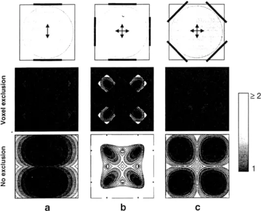
Fig. 1. Schematic representation of 1D and 2D SENSE acquisition a n d reconstruction with Cartesian sampling. A cylindrical object (top row) is imaged in a quadratic FOV with two PE directions. Three cases are shown: (a) ID SENSE with R = 2; (b) ID SENSE with R = 4 ; and (c) 2D SENSE with R = 2 x 2 = 4. Undersampling in SENSE acquisition results in aliasing after conventional Fourier reconstruction (bottom row). The degree of fi_)tdover is indicated by the gray-scale on the right. The aliasing is removed by SENSE reconstruction (top row). The dotted lines separate the parts of the FOV that are overlaid. As an example one set of superimposed voxels is indicated by the boxes.
12 M. ~I~2't~g, er et al. / Magnetic Resommce Mater&Is in Physics. Biology and Medicine I4 (2002) 10 - 19
the degree of aliasing is increased accordingly, and the distance of superimposed pixels is reduced. For R = 4 this is shown in Fig. lb. The same net reduction may be achieved though by applying SENSE wither = 2 to each of the two PE directions (Fig. l c). The grid describing the locations of the superimposed pixels is now two-dimensional, permitting four-fold aliasing of pixels spaced just as widely as in the 1D case with R = 2 (Fig. la).
Each coil element yields an aliased image as shown in the bottom row of Fig. 1, however, with an individ- ual intensity distribution reflecting the sensitivity roll- off of the respective coil element. In each aliased pixel value the signal components are individually weighted by the local coil sensitivity. Due to the distinctness of the coil elements, tl{is sensitivity contribution permits un/olding each pixel, yielding a full-FOV image with- out sensitivity weighting.
The formal description of the unfolding step, as given by Eqs. (1)-(3) in Ref. [5], is independent of the number o f encoding directions with reduced sampling density. The actual implementation of 2D SENSE es- sentially consists in correctly assembling the image val- ues and coil sensitivities in the respective vectors and matrices.
2.1.2. Signal-to-noise-ratio
The SNR at a location p in a SENSE image with respect to full Fourier encoding is
SNR rod = S NRfun- __,, .... -,, (1)
g~,,,//-R '
with go given by Eq. (23) in Ref. [5].
SNR t~H denotes the SNR of a fully Fourier-encoded image, obtained with the same coil array and other- wise identical parameters as the SENSE image. It cor- responds to a spatially varying noise level in the intensity-corrected flail-Fourier image, that has previ- ously been referred to as the basic noise of the array [12]. The basic noise is generally higher in the object center than at the object borders close to the coils. The local geometry factor g reflects the suitability of the coil array for distinguishing signal contributions from the originally aliased locations. It depends on the indi- vidual experimental setup, characterized by the coil configuration, the slice orientation, the FOV, and the degree of reduction. The geometry lector is ideally equal to one and usually grows as reduction increases. In the specific case of two coils, R up to two can be accomplished with very little noise enhancement. How- ever, with more coils unt~.vorably high geometry fac- tors tend to occur as the reduction factor approaches the theoretical limit given by the number of coil ele- ments.
Fig. 4 in Ref. [5] illustrates the effect of geometry-re- lated noise enhancement. With R = 2 the noise map is
nearly homogeneous showing low values on a relative scale. Correspondingly the SNR in the reconstructed image appears relatively uniform. With R = 4 the ge- ometry factor is locally increased causing much larger and strongly inhomogeneous noise. For a n intuitive understanding of this behavior, the aliasing process and its implications for the geometry factor shall be discussed explicitly for this setup as shown in Fig. 1. Geometry-related noise enhancement is a conse- quence of deteriorating condition of the matrix to be inverted in SENSE reconstruction. The condition, in turn, is determined by the distinctness of the coil sensi- tivities at the locations of the pixels that are superim- posed. F o r any pair of equidistant pixels in Fig. l a this distinctness is virtually perfect. However, coil sen- sitivities vary relatively smoothly, in particular at some distance from the coil conductors. Therefore the dis- tinctness of the local sensitivities deteriorates as the spacing of aliased locations decreases (Fig. l b)o In this respect, the situation depicted in Fig. l c is clearly superior, yielding R = 4 at the same pixel spacing as obtained with R - 2 in only one dimension.
The potential benefit of this improvement forms the focus of this work. As the properties of the used coil array have a strong influence on the geometry factor, different coil arrangements are considered. In this con- text it should be noted that the total SNR of a SENSE image, as given by Eq. (1), depends also on the basic noise of the array, which is subject to minor variation as coil elements are slightly shifted or changed in size. The resulting tradeoff was previously discussed in Ref. [12] for cardiac imaging with 1D SENSE. However, in the setups discussed in the scope of the present work, the net SNR is dominated by the geometry issue. Thus the behavior of basic noise is not explicitly demon- strated yet discussed where necessary.
2.1.3. Sensitivity assessment and voxel exclusion
Coil sensitivity maps as needed for SENSE recon- struction are determined experimentally by means of additional, fully Fourier-encoded reference images. For inherent homogeneity correction an additional body coil image with identical contrast is used. Based on the same reference data, regions that do not contribute significant signal may be excluded from SENSE recon- struction (voxel exclusion). In doing so, advantage is taken of the fact that the true degree of aliasing is locally reduced when one or more superimposed corn- ponents are zero. As a consequence, g decreases for the remaining, non-zero contributions, thus improving local SNR. In maps of the geometry t\actor, voxel exclusion is reflected by contours, which correspond to the object shape and indicate borders between regions with different degrees of aliasing. In vivo, pixels eligi- ble for exclusion are mainly bound outside of the body.
M. }i~2,iger et al./Magnetic Resonance Materials in Physics, Biology and Medicine I4 (2002) I 0 - I 9 13 2.2. Simulations
Simulations were performed in order to study geome- try-related noise enhancement in dependence on the coil configuration without experimental effort. A simulation tool was written in PV Wave language (Visual Numer- ics Inc., Houston, Texas) allowing interactive descrip- tion of an arbitrary FOV and coil setup. The coil sensitivities were calculated in the FOV on a 1282 grid in the quasi-stationary approximation by using Biot- Savart's law based on the reciprocity principle. Using the model underlying Eq. (A4)in Ref. [5], the receiver noise matrix 7' was approximated as described by Eq. (9) in Ref. [13] by pair-wise summing the scalar prod- ucts of the electric field over N = 203 equidistant loca- tions representing the object volume:
N
~r.:" = a ~ E:.(r,).E/(r,), (2)
i = 1
whereas unit conductivity cr throughout the object was assumed. This calculation is a correction to Eq. (7) in Ref. [12]. In this model, inductive coupling of the coils was neglected, assuming idealized receiver electronics. Using the calculated sensitivities and the receiver noise matrix, the geometry factor was determined for the full FOV. This was carried out with as well as without voxel exclusion to give a better insight into the robustness of the examined setups against variations of the object shape. From the resulting noise maps, gray- scale images were generated.
2.3. Materials
All experiments were performed at 1.5 T using a Philips Gyroscan ACS-NT15, providing six indepen- dent receiver channels. A custom-built coil array was used, consisting of six freely positionable elements (two circular: ~ = 20 cm, tour rectangular: 10 cm x 20 cm) [121.
3. Results
3. i. Simulations
Two different setups were considered in the simula- tions. Firstly, using an idealized basic setup general SNR properties of 2D SENSE were investigated and rules for appropriate coil positioning were derived. Secondly, these findings were applied to an in vivo setup t'or human head imaging.
As in conventional imaging, a basic prerequisite of the used coil array is that it should provide high and preferably uniform basic SNR. Thus, the coil elements ought to be of appropriate size for ensuring sufficient sensitivity in the center of the object [14]. Furthermore,
the elements should be uniformly distributed around the FOV. These two basic rules were taken into account in all simulations. In particular, the shapes and sizes of the elements were restricted to the two coil types de- scribed in Section 2.3, such as to match the dimensions of the two objects used.
3.1.1. Basic setup
Fig. 2 shows simulations corresponding to the situa- tion in Fig. 1, using a cylindrical object.with a length of 24 cm orientated along the Bo field direction. The diameter was ~ = 18 cm in a square FOV of (19.2 cm) 2 in the axial plane. Rectangular coils were placed around the object with the long dimension aligned along the cylinder axis.
In Fig. 2a, 1D SENSE with R = 2 was applied to the vertical PE direction using two coils, one on either side of the object. The calculated geometry factors are shown for reconstruction with and without voxel exclu- sion. Both maps show the expected low values and a relatively homogenous distribution. The maximum and mean values of g are 1.3/1.1 with, and 1.8/1.2 without voxel exclusion, respectively. Comparison the two maps reveals the beneficial effect of voxel exclusion, reducing the geometry /:actor at all locations with no actual aliasing as shown in Fig. l a.
In Fig. 2b, 2D SENSE was applied with R = 2 x 2 = 4 by additional reduction in the horizontal PE direc- tion. The observation of low g in the 1D case suggests to analogously place two additional coils for the second PE direction. However, somewhat contrary to intuition, the geometry /'actor now exhibits strong peaks. With voxel exclusion, a maximum value of 3.4 occurs in the regions involved in four-fold aliasing. Assuming a com- pletely filled FOV, the largest values even exceed 200. These results indicate that in some regions the used coil configuration provides insufficient 'differences' in its coil sensitivities for the respective sets of superimposed voxels.
In Fig. 2c, the setup was slightly changed by rotating the coil array by 45 ~ with respect to the orientation of the FOV. By this modification the resulting geometry factor was drastically improved. The maximum and mean values were reduced to 1.2/1.1 and 3.7/1.4 with and without voxel exclusion, respectively. The depen- dence of g on the rotation angle is a monotonous function that increases slowly for deviations from the optimal position of Fig. 2c and peaks sharply at a zero rotation angle corresponding to Fig. 2b.
Even though not obvious at first sight, the observed behavior can be understood by considering that the aliasing process essentially superimposes a number of image sections. In Fig. 2b and c these are the four image quadrants. In the configuration of Fig. 2c each coil is placed in the corner of such a quadrant, covering it uniquely and thus p e ~ i t t i n g well-conditioned un-
14 M. Weiger et a l . / M2lgnetic Resonance Materials in Physics, Biology and Medicine 14 (20(.)2) I0-19
Fig. 2. Simulation of geometry,related noise enhancement using the basic setup. Top row: a cylindrical object was assumed in a square FOV with two PE directions. Rectangular coil elements are indicated by black bars. Mi&lle row: geometry factor in the FOV with voxel exclusion. Boltom row: geometry l'actor without voxel exclusion. (a) 1D SENSE with R = 2 and two coils. (b) 2D SENSE with R = 2 x 2 = 4 and four coils, and (c) the same setup as in (b) but with the array rotated by 45 ~
folding. In principle, the same consideration applies for the two halves in the simpler case in Fig. 2a. Opposed to that, in Fig. 2b each coil covers two quadrants in a similar fashion, making the separation more difficult. These observations suggest that prefer- ably each aliasing component of an object should be individually covered by one coil element.
3.1.2. In vivo s e t u p
The previously described guidelines for configuring the coil elements were applied to human head imaging. For simulation purposes the head was approximated by an ellipsoid with diameters of 20, 18, and 24 cm in anterior-posterior (AP), .right-left (RL), and feet- head (FH) direction, respectively. F H was aligned with the Bo field direction.
A standard situation for 3D imaging of the h u m a n brain is depicted in Fig. 3a. The imaging volume cov- ers the head completely in the axial plane, using FOVs of 21.6 cm in AP and 19.2 cm in RL direction. In the F H direction the volume is restricted to the extent of the brain by slab-selective excitation and using a FOV of 13 cm. Usually, for most time-efficient imaging, frequency encoding is performed along the longest di- mension of the imaging volume. In Fig. 3a this direc- tion is AP, and PE is applied in the depicted plane
along the RL and F H directions. In agreement with the given rules, iterated simulations yielded the de- picted four-coil configuration as most suitable for this task. Note that adjacent coils do not overlap, as found advantageous in earlier studies [12]. The simulation result for the c e n t r a l s l i c e with voxel exclusion is shown in the middle row of Fig. 3a. The geometry factor is relatively homogeneous with a mean value of 1.1. However, there are peaks w i t h maximum values up to 2.1 that are partly located in the object center. This behavior becomes more obvious without voxel exclusion with a mean value of 1.5 and the maxima exceeding 200. The difference of the two g maps demonstrates that even though the configuration may well provide relatively low noise enhancement it is potentially susceptible to variations of the object shape
and size. ~
The difficulties with this setup arise from the fact that the various demands on the coil configuration cannot quite be fulfilled simultaneously. With the given size of the coil elements, which is appropriate in terms of sensitivity at the center, the aliased image sections cannot really be separately covered. In addi- tion, the two b o t t o m coils cannot be placed in the corners of the FOV and the top coils suffer from reduced sensitivity due to their inclination towards the Bo field.
M. Weiger et al./Magnetic Resonance Materials in Physics, Biology and Medicine I4 (2002) 10-19 15
In order to improve the situation for 2D SENSE imaging the setup was modified by enlarging the imag- ing volume in the FH dimension to 25.6 cm. Frequency encoding was then applied to this new largest dimen- sion, and PE was performed in the transverse plane as depicted in Fig. 3b. The new situation is very similar to the earlier basic setup, thus the four rectangular coils were arranged according to Fig. 2c. Not surprisingly, the results are very similar with nearly identically low values of the geometry factor.
However, the setup in Fig. 3b cannot entirely fulfill the basic prerequisite of the coils being uniformly dis- tributed around the object, thus causing a sensitivity drop-off between the top and the bottom pair of coils. Yet due to the oval shape o f the object more coil elements can be used. In this case the rule-of-thumb which suggests assigning each aliased section to a sepa- rate coil is not quite applicable, as the number of coils exceeds the number of sections. Nevertheless, using the available coil types, iterated simulation still yielded a rather intuitive optimal configuration, as displayed in Fig. 3c. Two additional, larger circular coils were placed at the positions with greater distance from the
object center whereas the rectangular coils were posi- tioned laterally in non-overlapping pairs. The simulated maximum and mean values of g are 1.7/1.1 with, and 3.t/1.4 without voxel exclusion. Though these values are larger than for the setup in Fig. 3b, the total SNR is improved for two reasons. Firstly, the basic noise of this arrangement is slightly lower and more homoge- neous. Secondly, the large g-values appear exclusively in border regions close to the coil, where the basic noise of the array is considerably lower than in the center of the object.
3.2. Experiments
For verification of the simulation results and for demonstrating the in vivo feasibility of 2D SENSE, the setup in Fig. 3c was realized experimentally. Coil ar- rangement, FOVs, encoding directions, and SENSE reduction were chosen identically to the simulations. Three-dimensional imaging was performed using a T1- weighted (RF-spoiled), flow-compensated gradient echo sequence (~/TE/TR = 20~ ms/10.2 ms). A matrix of 128 x 96 x 108 was acquired yielding an isotropic reso-
Fig. 3. Three in vivo setups for head imaging with 2D SENSE. Top row: the head is represented by an ellipsoid; the flame depicts the respective FOV with two PE directions. Rectangular coils of 10 cm x 20 cm are shown in black, whereas circular coils with ~ = 20 cm are shown as gray bars. MMdle row: geometry tactor in the FOV with voxel exclusion. Bottom row: geometry factor without voxel exclusion. (a) Standard setup for brain imaging with a slab-selective excitation in FH direction. The PE directions are FH and RL and four coils are used. (b) Modified setup with the imaging volume extended in the FH direction for improved performance of 2D SENSE. PE is now applied along AP and RL and the four coils are arranged according to Fig. 2c. (c) Same FOV as in (b) using six coils.
16 M. ~-{';eiger et al./Magnetic Resonance Materials in Physics, Biology and Mea'icine 14 (2002) I 0 - 1 9
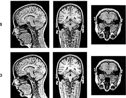
Fig. 4. In vivo imaging vdth 2D SENSE using the setup in Fig. 3c. The acquisition with 2D SENSE and R = 2 x 2 = 4 took 26.5 s (a) whereas conventional Fourier encoding required 106 s (b).
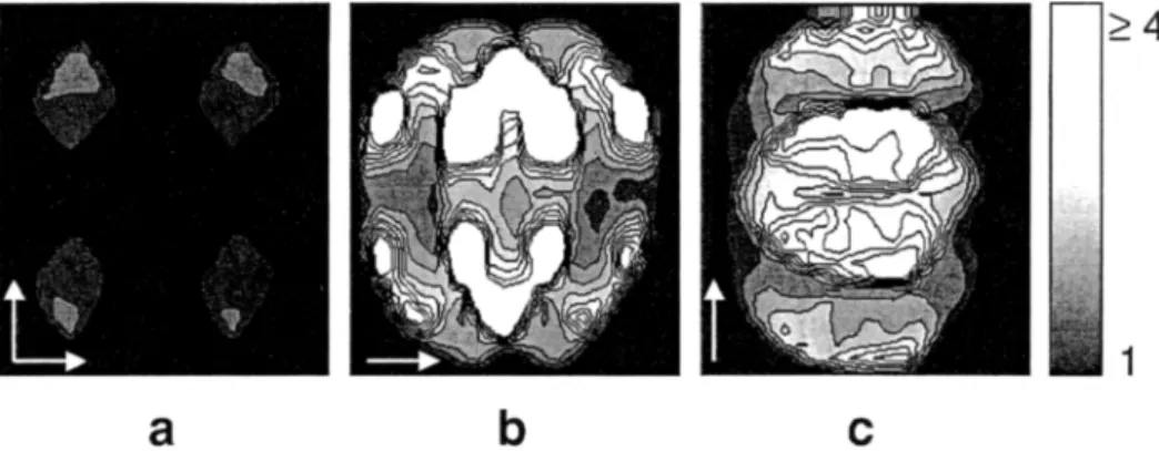
lution of" 2 mm. Sensitivity assessment was based on a 3D reference data set of the same imaging volume with a resolution of 4 ram. The reference data was acquired with the array and the body coil in an interleaved mode in 6 s using a gradient-spoiled EPI sequence (six echoes per excitation, half Fourier acquisition with 62.5% of PE lines). The scan time of the conventional acquisition with full Fourier encoding was 106 s. The 2D SENSE scan was performed four times faster in 26.5 s. The results are displayed in Fig. 4 showing three selected orthogonal slices. The data sets appear identical con- cerning resolution and contrast. However, the SNR of the SENSE acquisition is visibly lowered, in particular in the nedk region where net sensitivity drops. The geometry/'actors of the data were calculated with voxel exclusion from the coil sensitivities, and the result for a central transverse slice is presented in Fig. 5. The geometry factor of the 2D SENSE scan in Fig. 5a shows strong similarities to the simulation in Fig. 3c with comparably small maximum and mean values for g of 2.2 and 1.2, respectively. The remaining differences arise from deviations of the oNect shape and certainly also from limitations of the simulation model. As al- ready observed in the simulations, the largest noise enhancement for this setup occurs in the object corners, where the basic noise of the array is known to be relatively low. This results in a balanced final noise distribution that is the product of the basic noise and g. The total SNR reduction of the 2D S E N S E scan with
respect to the fially Fourier encoded one was calculated using Eq. (1). With R = 4 and using the above g-values, the values for maximum and mean total SNR reduction are 4.4 and 2.4, respectively. For comparison the ge- ometry factors were also calculated for 1D SENSE with the same setup and reduction of R = 4. As expected the results show strong noise enhancement for both reduc- tion in RE direction (Fig. 5b, maximum:
26.6,
mean: 3.6) and in AP direction (Fig. 5c, maximum: 7.4, mean: 2.7).4. Discussion
2D SENSE has been presented as a means of improv- ing the encoding efficiency in 3D imaging. The proper- ties of the technique were studied using simulations, and practical setups were developed. In vivo imaging was successfully performed with four-fold 2D SENSE reduction. It has been found that in the used setup 2D SENSE was clearly superior to 1D SENSE due to significantly reduced geometry-related noise enhancement.
Simulations focused on the geometry factor revealed important properties of 2D SENSE, emphasizing the crucial role of the coil configuration with respect to net SNR. In this context it was found that increasing degrees of aliasing make the influence of the coil sensi- tivities difficult to understand intuitively. Therefore,
M. Weiger et al./Magnetic Resonance Materials in Physics, Biology and Medicine I4 (2002) 10-19 17 such simulations form the method of choice for opti-
mizing the coil configuration and for judging the useful- n e s s of 2D SENSE for a specific application with minimal effort. The used simulation approach proved fairly reliable in reflecting the in vivo situation. How- ever, if more accurate results are required, mutual coil coupling and a model for the conductivity distribution should be included. Furthermore, the quasi-static ap- proximation has only limited applicability, in particular when considering field strengths higher than 1.5 T.
As a guideline for the coil arrangement it was found that in the first place the usual rules for array configu- ration should be observed, i.e. the elements should be of appropriate size with respect to the object and uniformly distributed. Furthermore, for 2D SENSE each aliased section of the imaging volume should preferably be individually covered by one coil. If the number of coils exceeds the total reduction factor, it is more difficult to derive general rules for optimal perfor- mance, making simulations indispensable.
The presented simulations of the geometry factor included reconstruction both with and without voxel exclusion. On the one hand, this demonstrated the important role of voxel exclusion in achieving the low- est possible noise enhancement. On the other hand, taking into account the performance without voxel exclusion provides information about the robustness of a coil arrangement against minor variations of the geometrical setup. If a g map determined for a fully filled FOV exhibits the main peaks in border regions as in Fig. 3b/c, the corresponding setup will not cause a sudden increase of g for limited changes in coil posi- tioning, FOV, or object size and shape.
The results of this work were represented only by sample central slices. It was found though that the geometry factor behaves similarly througho.ut the imag- ing volume, except for regions close to the borders of the coil array. Therefore, just as in conventional 3D imaging, it is important to make sure that the imaging
volume is sufficiently covered by the array. In auto- mated 3D imaging with SENSE it would seem advis- able to evaluate the expected noise level throughout the imaging volume prior to definitive data acquisition.
A net SENSE reduction of R = 4 , resulting from two-fold reduction in each of the two PE directions, was studied in this work. F o r each potential applica- tion, the actually used reduction factors should be individually adapted, depending on the specific geomet- rical situation and the S N R requirements. As an impor- tant feature in terms of optimizing protocols, the SENSE approach allows for non-integer reduction, re- suiting in a spatially dependent degree of aliasing. Therefore, 2D SENSE may be superior to the I D method even at net reductions less than four. Higher reduction is generally possible as long as the largest actual degree of aliasing is not larger than the number of coils. However, for the reasons discussed in Section 2, strong geometry-related noise enhancement becomes increasingly difficult to avoid at reduction factors be- yond two in each PE direction. S E N S E with high reduction factors clearly benefits from increasing the number of independent receiver channels. It remains to further study, however, to which degree the geometry issue can actually be mitigated by using considerably more than six coil elements.
When selecting,, a conventional ima~in,,,, = protocol for the application of 2D SENSE, various ways of utilizing the improved encoding efficiency can be envisioned. The scan time can be shortened, the spatial resolution can be improved, or the imaging volume can be ex- tended. In all cases, one has to take care of maintaining sufficiently high SNR. The basis for this task is finding a coil arrangement with the lowest possible geometry- related noise enhancement. Furthermore one must con- sider that in each case sensitivity encoding affects the SNR in a slightly different fashion. The SNR drawback of simply reducing scan time is described by Eq. (1), including the SNR reduction by , j ~ due to less Fourier
Fig. 5. Geometry factors in the in vivo experiment. The results are calculated with voxel exclusion based on measured coil sensitivities and shown l;ar a central axial slice. (a)2D SENSE experiment. Note that the strongest noise enhancement occurs close to the object borders where the basic noise is low. (b) 1D SENSE with R =4 in RL direction. (c) ID SENSE with R =4 in AP direction. Note the much better performance of 2D SENSE as compared with 1D SENSE at the same total reduction factor.
18 M. Weiger et al./Magnetic Resonance Materials in Physics, Biology and Medicine I4 (2002) 10-19 encoding steps. As side effects this usage of SENSE can
reduce motion artifacts or increase patient comfort by enabling shorter breath hold duration. In the case of improving spatial resolution, the impact of the. reduced voxel size on the SNR has to be taken into account, as discussed in Ref. [10]. The third option, i.e. increasing the imaging volume is demonstrated in this work, when considering the change from Fig. 3a to Fig. 3b/c. This mode permits better coverage o f the anatomy of inter- est without increasing scan time or sacrificing resolu- tion. In terms of SNR, extending the imaging volume is the least critical usage, for two reasons. On the one hand, a larger imaging volume permits easier access fi~r the required number of well separated coils, thus reduc- ing geometry factors. On the other hand, as compared with reducing scan time and improving resolution, this mode provides superior SNR due to a greater number of signal samples and to larger voxel size, respectively. A variety of applications will potentially benefit from 2D SENSE, including brain, abdominal, and cardiac imaging. In the present work, head imaging was per- formed as an example. However, the results may read- ily be transferred to other imaging tasks, as long as the relations of object size, FOV, and coil size are compara- ble. As a rule-of-thumb, for best performance the FOV should have similar size in the two PE directions. The setup should permit arranging as many coils as possible in the PE plane and close to the FOV, while keeping the elements large enough to provide sufficient sensitiv- ity at object depth.
Special considerations are necessary far contrast-en- hanced angiography (CE-MRA), which forms a partic- ularly promising field of application. As already demonstrated with ID SENSE [10], the specific prob- lems related to venous enhancement, bolus timing, and breath-holding can be elegantly tackled by reducing scan time. Special advantages of C E - M R A are the relatively high basic signal level and the flexibility in influencing the SNR by choosing the injection rate and the dose of the contrast agent, as also discussed in [15]. Similar t o t h e standard brain protocol in the present work, the abdominal protocol used in Ref. [10] is not well suited for direct application of 2D SENSE for the purpose of reducing scan time. This is due to the relatively narrow slab in the AP PE direction which is not accessible for coils with sufficient penetration depth. Here again, increasing the imaging volume would be the better option.
A very different application that already proved suc- cessful with 2D SENSE is spectroscopic imaging (SI) [16]. F o r imaging a single, spectrally resolved slice, standard SI requires two spatial PE directions as spec- tral encoding precludes frequency encoding. The need for very long repetition times causes scan times on the order of tens of minutes which makes SENSE reduction particularly beneficial. ....
Another variant of 2D SENSE may be just depicting multiple slices rather than a 3D volume. As proposed in Ref. [17], multiple slices can be excited simultaneously, imaged by a 2D scheme, and then separated using sensitivity int:ormation. If all sets (e.g. pairs) of slices are at the same distance, SENSE reconstruction o n such a multiple-slice data set works identical as on 3D Fourier data. Only the Fourier transf'orm has to be skipped in the direction where PE is replaced by slice selection. This variant would have the same properties concerning the geometry factor as the 3D Fourier case discussed in this work. In certain situations, however, choosing other than equidistant sets of slices may be advantageous in terms of noise enhancement in multi- ple-slice imaging.
Acknowledgements
The authors would like to thank Christoph Leussler and Peter R6schmann from the Philips Research Labo- ratories in Hamburg, Germany, who built the six-ele- ment coil array. Technical support was granted by Philips Medical Systems in Best, The Netherlands. The work was financially supported by the E U R E K A grant EU2061 and KTI 4178. I.
References
[101
[11]
[1] Hutchinson M, Raft U. Fast MRI data acquisition using multi- ple detectors. Magn Reson Med 1988;6:87-91.
[2] Kelton JR, Magin RL, Wright SM. An algorithm for rapid image acquisition using multiple receiver coils. Proceedings of the SMRM, 8th Annual Meeting, Amsterdam. 1989. p. 1172. [3] Ra JB, Rim CY. Fast imaging using subencoding data sets from
multiple detectors. Magn Reson Med 1993;30:142-5.
[4] Sodickson DK, Manning WJ. Simultaneous acquisition of spa- tial harmonics (SMASH): ultra-fast imaging with radiofrequency coil arrays. Magn Resort Med 1997;38:591-603.
[5] Pruessmann KP. Weiger M, Scheidegger MB, Boesiger P. SENSE: sensitivity encoding for fast MRI. Magn Reson Med 1999;42:952-62.
[6] Kyriakos WE, Panych LP, Kacher DF, Westin C-F, Bao SM, Mulkern RV. et al. Sensitivity profiles from an array of coils for encoding and reconstruction in parallel (SPACE RIP). Magn Reson Med 2000;~:301-8.
[7] Griswold MA, Jakob PM, Nittka M, Goldfarb JW, Haase A. Partially parallel imaging with localized sensitivities (PILS). Magn Reson Med 2000;44:602-9.
[8] Weiger M, Pruessmann KP, Boesiger P. Cardiac real-time imag- ing using SENSE. Magn Reson Med 2000;43:177-84.
[9] Pruessmann KP, Weiger M, Boesiger P. Sensitivity encoded cardiac MRI. J Cardiovasc Magn Reson 2001;3:1-9.
Weiger M, Pruessmann KP, Kassner A, Roditi G, Lawton T, Reid A, et al. Contrast-enhanced 3D MRA using SENSE. J Magn Reson Imaging 2000;12:671-7.
Golay X, Pruessmann KP, Weiger M, Crelier GR, Folkers PM, Kollias SS, et al. PRESTO-SENSE: an ultra-fast whole brain ~4RI technique. Magn Reson Med 2000:43:779-86.
M. Weiger et al./Magnetic Resonance Materials in Physics, Biology and Medicine 14 (2002) I0-19 19 [12] Weiger M, Pruessmann KP, Leussler C, Roeschmann P, Boe-
siger P. Specific coil design for SENSE: a six-element cardiac array. Magn Reson Med 2001:45:495-504.
[13] Roemer PB, Edelstein WA, Hayes CE, Souza SP, Mueller OM. The NMR phased array. Magn Reson Med 1990;16:192- 225.
[14] Wang J, Reykowski A, Dickas J. Calculation of the signal-to- noise-ratio for simple surface coils and arrays of coils. IEEE Trans Biomed Eng 1995;42:908-17.
[15] Weiger M, Pruessmann KP, Hilfiker PR, Weishaupt D, Boesiger
P. Increasing the SNR in steady-state imaging by sensitivity encoding. Proceedings of the ISMRM, 8th Annual Meeting, Glasgow. 2001. p. I798.
[16] Dydak U, Weiger M, Pruessmann KP, Meier D, Boesiger P. Sensitivity-encoded spectroscopic imaging. Magn Reson Med 2001;46:713-22.
[17] Larkman DJ, Hajnal JV, Herlihy AH, Coutts GA, Young IR, Ehnholm G. Use of multi-coil arrays for separation of signal from multiple slices simultaneously excited. J Magn Reson Imag- ing 2001;13:313-7.