Publisher’s version / Version de l'éditeur:
Vous avez des questions? Nous pouvons vous aider. Pour communiquer directement avec un auteur, consultez la
première page de la revue dans laquelle son article a été publié afin de trouver ses coordonnées. Si vous n’arrivez pas à les repérer, communiquez avec nous à [email protected].
Questions? Contact the NRC Publications Archive team at
[email protected]. If you wish to email the authors directly, please see the first page of the publication for their contact information.
https://publications-cnrc.canada.ca/fra/droits
L’accès à ce site Web et l’utilisation de son contenu sont assujettis aux conditions présentées dans le site LISEZ CES CONDITIONS ATTENTIVEMENT AVANT D’UTILISER CE SITE WEB.
FOAMS 2009: Seventh International Conference on Foam Materials &
Technology [Proceedings], 2009-09-16
READ THESE TERMS AND CONDITIONS CAREFULLY BEFORE USING THIS WEBSITE. https://nrc-publications.canada.ca/eng/copyright
NRC Publications Archive Record / Notice des Archives des publications du CNRC :
https://nrc-publications.canada.ca/eng/view/object/?id=6f3cb727-04e6-415b-a8a8-849b2b54abd2 https://publications-cnrc.canada.ca/fra/voir/objet/?id=6f3cb727-04e6-415b-a8a8-849b2b54abd2
NRC Publications Archive
Archives des publications du CNRC
This publication could be one of several versions: author’s original, accepted manuscript or the publisher’s version. / La version de cette publication peut être l’une des suivantes : la version prépublication de l’auteur, la version acceptée du manuscrit ou la version de l’éditeur.
Access and use of this website and the material on it are subject to the Terms and Conditions set forth at
Nanoporous multilayer structures induced in Cyclo-Olefin copolymers :
Structural characteristics and optical properties
Nanoporous Multilayer Structures Induced in Cyclo-Olefin Copolymers:
Structural Characteristics and Optical Properties
Richard Gendron, Michel F. Champagne and Martin N. Bureau
National Research Council of Canada, Industrial Materials Institute
75, de Mortagne Blvd, Boucherville, Quebec, CANADA J4B 6Y4
Abstract
Unusual structures consisting of alternating stacks of 200 nm-thick nanoporous and 5 to 20 m-thick pore-free layers were obtained with cyclo-olefin copolymer thin sheets. Such copolymer is well-known for its remarkable optical properties. The structural configurations induced during foaming provide high reflectivity in the visible spectrum along with partial transmittance in the UV and visible ranges depending on the microstructural characteristics of the porous layers. Adequate load applied to the sheet can nevertheless eliminate this reflectivity as these low-density foamed layers remain very pressure-sensitive. It is postulated that the mechanisms leading to such an intriguing structure is related to a spinodal decomposition.
Introduction
In a previous study, we have explored the foaming ability of a commercially available cyclo-olefin copolymer (COC) of norbornene-ethylene (Topas resin), using the solid-state foaming method [1,2]. Our previous work was conducted using a novel approach based on the use of a Brückner biaxial laboratory sheet stretcher (Karo IV), programmed to compensate uniformly for the expansion of the sheet by stretching, which allowed to produce large and flat samples. Low-density samples were easily
produced at moderate CO2 content (4 wt%), obtained
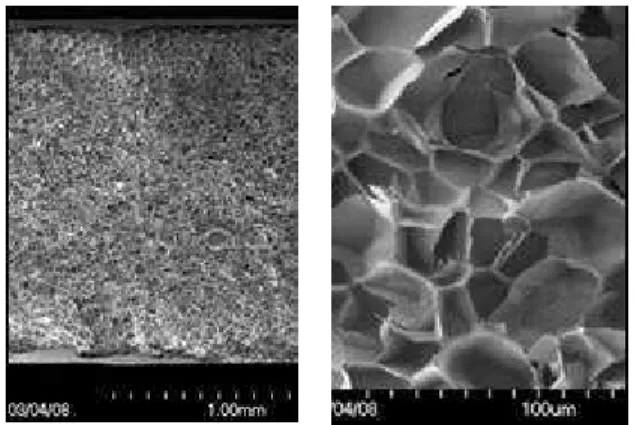
under subcritical conditions (neat Topas 1.5 mm-thick sheet charged at room temperature and pressure lower than 5.5 MPa). As frequently observed with the solid-state foaming approach, gas depletion quickly occurred at the surface of the sheet, resulting in the thin (≈15 µm thick) dense skins on both sides of the sheet as shown in Figure 1. The size of the cells depicted in this figure lies between 10 and 35 m, which correspond to the range inherent to microcellular foams.
This work has also highlighted the benefit of using such set-up and method to produce foam sheet prototypes that can be further molded through thermoforming, for instance. The quality of the foams obtained, as well as the diversity in densities and morphologies achievable, make this unusual approach an interesting alternative to validate
the foamability of novel polymers and blends while keeping foamed prototypes of industrially-sound dimensions as final target. This is especially true for costly resins or materials available on a small scale basis.
Figure 1. Magnification of a sheet of COC Topas 5013 foamed with 3.0wt% of CO2. The resulting foam had a density of 81 kg/m3, with mean cell size of 19.7 m.
Applicability to other resins was validated using modified-glycol poly(ethylene terephthalate) (PETG) and polycarbonate (PC). Nice microcellular foamed sheets of low density, in the 100 kg/m3, were easily obtained using carbon dioxide. Morphology of these foams is illustrated in Figure 2. While the PC foam displays a homogeneous structure, the PETG exhibits an unusual two-dimensional layered structure that can be imparted to the diffusion of the carbon dioxide toward the sheet surface and/or the planar heat flux coming from both sides of the sample (top and bottom on the photograph). The lower nucleation density and large cell morphology lying close to the center of the foam sheet should be indubitably linked to a lower content of foaming agent. However such explanation could not fit the morphology at the mid-plane, where numerous small cells co-exist adjacent to the larger ones.
Other results showing lamellar morphologies were obtained under various conditions (time, temperature, gas concentration), this time with a COC polymer. A multilayer structure was obtained with presence of alternating nanoporous and unfoamed layers. The present study focuses on these unexpected results, and the impact of their structure on the optical properties.
Figure 2. Top: PC foam; bottom: PETG foam. Both foamed sheets have density close to 100 kg/m3.
Experimental
The polymer used was an ethylene-norbornene copolymer from Topas, grade 5013, with a glass transition temperature of 135oC. Properties of this resin are detailed in Ref. [2]. Sheets of this material have been obtained by extrusion, with thicknesses varying between 1.0 and
1.5 mm. Similar experiments as those conducted in
Ref. [1] and [2], based on the solid-state foaming process adapted to a Brückner biaxial laboratory stretcher (Karo IV), were performed, but without inducing any stretch (draw ratio of 1x1). The morphology of the resulting sheets was characterized using scanning electron microscopy (SEM) with a Hitachi SR-4700 microscope. Optical transmittance in the 200-2300 nm range (from ultraviolet to near infrared) was also investigated using a Lambda 950 UV/Vis/NIR spectrophotometer from PerkinElmer.
Results and Discussion
Nanoporous Multilayer Structure
Solid-state foaming experiments have been conducted under specific conditions, described elsewhere [3]. Since the expansion was expected to be very low, no stretching was programmed for these experiments. Surprisingly, mirror-like sheets were obtained after the set soak time inside the biaxial stretcher oven. Such appearance could be repeatedly obtained, with a white cloudy surface for some of the samples as shown in Figure 3.
Figure 3. Examples of mirror-like sheets (10 x 10 cm2) resulting from particular processing conditions. Marks on the side of the sheets are due to the grips of the biaxial stretcher.
1m
Figure 4. Micrograph of the sample shown at the right of Figure 3, illustrating the various layers present through the thickness of the “foamed” sheet, with magnification of the sub-structures.
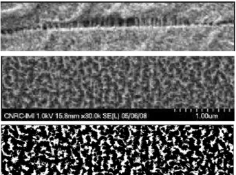
These visual characteristics could be explained by the presence of some distinct morphological features, as highlighted in Figure 4. This figure illustrates that such morphology was symmetrical with respect to its mid-plane, with three main different sections composing it. First, the layer close to the surface, corresponding to one fourth of the overall thickness, remained unfoamed. Next layer, also one fourth of the thickness, was composed of microcells having diameters less than 10 m. This layer was responsible for the white cloudy feature, as shown in Figure 3 (right). Finally the high reflectivity of the sheet could be associated to the main layer representing half of the thickness, where numerous 5 to 10 µm thick layers were stacked and barely separated by nanoporous gaps,
each gap being approximately 200 nm-thick (see
magnification at bottom of Figure 4). These thin porous layers consisted of fibrils having diameters less than 10 nm. The fibrils joined both sides of the adjacent thicker layers, apparently bridging them. Surprisingly, these micro-layers as shown on the same magnified picture exhibited a pore-free structure.
Applying a pressure of roughly 10-20 MPa made the sheet transparent again: the nanoporous gaps would have collapsed and densified under such stress. Assuming that this load value can be associated with the stress at yield (value at the plateau before densification) of foams made of similar material [4], the corresponding porous layers would have a density 350 kg/m3. This is in agreement with the (surface) density estimated from a high contrast micrograph of the surface a delaminated layer, as shown in Figure 5. It is worthwhile mentioning that the morphology depicted in this last micrograph is reminiscent of spinodal decomposition snapshots usually reported to support such phase-separation mechanism. This aspect will be covered in a further section.
Figure 5. Details of the nanoporous section: (top) Side view; (middle) top view of a delaminated sample; (bottom) high contrast view of the previous picture, with the white fraction (34% of the overall surface) being associated to the polymer struts or fibrils.
Applying pressure at definite locations also enabled the creation of transparent windows, as shown in Figure 6. The reflective structure is preserved elsewhere.
Figure 6. Sketch drawing on a thin pressure-sensitive sample, using the tip of a standard pen.
The layered structure is also sensitive to the temperature. When the temperature was raised above the glass transition temperature of the resin used, in the present case Tg=135oC, the reflective appearance was lost,
indicating a collapse of the porous gaps. A similar layered structure with silver-like appearance has been reported before by Handa and Zhang [5]:
« Nanolayered polystyrene sheet: the material has
an opaque silvery appearance due to the light reflected by the inside layers and the light scattered by the gas-filled gaps. ».
Despite the similarities in the end-product, their processes relied on specific processing steps absent from our approach. In one case, for what they referred as “nanolayer process”, stacks of multiple layered polymer pieces were built through compression molding, with deliberately inducing between the layers a low degree of interfacial entanglements. A blowing agent was further dissolved in this polymer assembly, and phase separation occurred following the easiest path, i.e. at the weakly bonded layer surfaces. Thickness of the polymer layers were dependent upon the material thickness used in the compression molding stage. Handa and Zhang also introduced the “microlayered process”, where phase separation is induced through high stresses applied to the polymer sheet using compression molding again. Growing cells tended then to grow in the directions normal to the applied stress.
Our samples were obtained from extruded films or sheets, in which cases one would usually expect an adequate level of melting of the granules and no reminiscence of this original state after the extrusion step. In the case where the chain orientation due to sheet extrusion may have come into play, some of the extruded sheet samples were also submitted to annealing through post compression molding at a temperature sufficiently high to erase the shear history. Even for these specimens, a layered structure has developed. Thus the layered
configuration we have obtained was not the result of any structure remaining from the initial sheet forming process. Unfortunately, while Handa and Zhang have characterized their layered foams in terms of thermal conductivity and dielectric properties, such work remain to be performed in the present case. Nevertheless, it can be anticipated that the present multilayer structures should share similar properties related to thermal, electrical and sound applications.
Structure versus Optical Properties
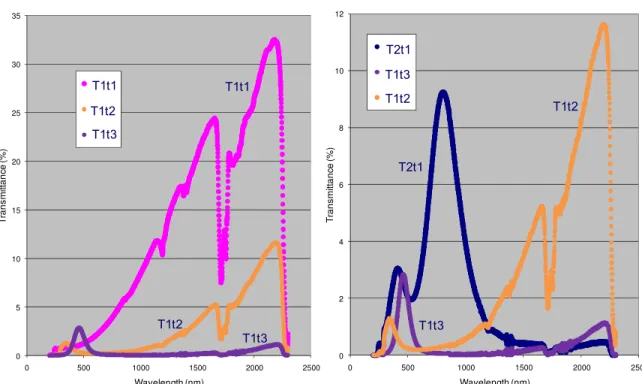
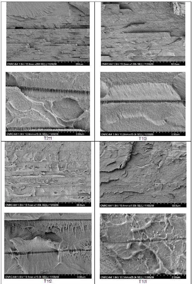
Four different samples have been examined more closely in an effort to relate some of their morphological characteristics to optical behavior. Three sheets coded T1t1, T1t2 and T1t3, were produced with increasing time spent in the biaxial stretcher oven, while maintaining the same temperature. The fourth sample coded T2t1 was obtained at a much higher temperature, with a soak time similar to that of T1t1. The transmittance spectra in the UV-visible-NIR regions for those four sheets are displayed in Figure 7, and their morphologies illustrated in Figure 8 at two different magnifications such as to quantify the order of magnitude of the thickness of the unfoamed layers as well as the porous gaps.
Various observations and correlations can be made from these two sets of figures:
- Temperature had a significant impact on the unfoamed layer thickness: for the samples obtained at T1 these layers are approximately 10-15 m thick, while this thickness decreases down to 5-10 m at the higher temperature T2.
- Keeping the temperature constant, a longer soak time broadened the nanoporous gap, from less than 50 nm for T1t1 to approximately 200 nm for T1t3.
- Increasing the thickness of the nanoporous layer had serious impact on the transmittance, with the sample being almost opaque to any wavelength (visible and NIR regions) in the case of T1t3.
- Such absence of transmittance is also observed in the case of sample T2t1 although a significant peak at the border of visible-NIR regions is clearly visible: this peak occurs at approximately 800 nm, along with a second peak at 400 nm as its first harmonic. Similar but less intense peaks can also be observed for T1t2 and T1t3, this time in the UV region.
- Such transmittance, even if its level remains relatively low, seems to be correlated with the thickness of the nanoporous gap, in terms of wavelength and amplitude. The smaller the gap, the shorter the wavelength. The optical mechanism leading to this behavior has not been identified yet.
0 5 10 15 20 25 30 35 0 500 1000 1500 2000 2500 T ra ns m it ta nc e ( % ) Wavelength (nm) RE9_1 RE8_1 RE7_1 T1t1 T1t3 T1t2 T1t1 T1t2 T1t3 0 2 4 6 8 10 12 0 500 1000 1500 2000 2500 T rans m it tanc e (% ) Wavelength (nm) NA1_1 RE7_1 RE8_1 T2t1 T1t2 T1t3 T2t1 T1t3 T1t2
Figure 7. Transmittance spectra in the UV-visible-NIR regions for the four samples. Please note that the two graphs have different scales for the Y-axis (transmittance level).
Figure 8. Morphology of four samples (cryogenic fracture through thickness) at two different magnifications, with emphasis on (a) unfoamed layers and (b) nanoporous gaps.
Proposed Mechanism: Lamellar Spinodal Decomposition
Foaming implies a phase separation in the polymer/foaming agent blend that occurs through thermodynamic instabilities induced by either pressure or temperature quench. This phase separation can follow two different paths in terms of mechanism: cell nucleation and growth prevails for most of the cases (metastable region). However under certain critical conditions, with a deep and rapid quench beyond the binodal border, spinodal decomposition occurs. This mechanism relies on compositional waves (concentration fluctuations) having amplitudes that grow by “uphill diffusion.”
An isotropic structure is usually expected from spinodal decomposition since the composition waves have vectors in all directions. Nevertheless, layered structures obtained through such mechanism have been previously reported. A particular case has been termed “surface-directed spinodal decomposition”, because of the preferential attractive interaction for one of the components with respect to the surface [6]. This interaction induces a concentration gradient that affects the segregation of the two species. Distinct layers are thus found near the surfaces, but not in the bulk.
In our situation, a concentration gradient of the dissolved gas has been induced through its depletion near the surfaces of the sheet: gas molecules are obviously “attracted” outside the polymer sample via atmospheric desorption. This occurs during the transfer of the gas-charged sheets from the autoclave to the oven, transfer done under atmospheric conditions. In addition, thermal transfer during the temperature quench in the Brückner oven proceeded essentially from surface to core given the geometry of the sample, thus a temperature gradient is also induced, normal to the surface.
It can be anticipated that as the gas concentration fluctuations grow in amplitude during the spinodal decomposition, higher plasticization prevails in gas-rich planes parallel to the surface (in rubbery phase), alternating with gas-depleted layers (in glassy state). This would eventually lead to weakly bonded glassy polymer layers and ultimately to their debonding as the gas expelled from the matrix exerts a pressure on the adjacent surfaces.
Time-scale associated with this process can be very short due to the high mobility of one of the two components, i.e. the gas, as set by its relatively high diffusivity coefficient (in the order of 10-8 cm2/s). This diffusivity coefficient even drastically increases to higher values (hundred to thousand-fold) when the glass temperature of the plasticized polymer lies much below that of the processing temperature [7]. This bares no comparisons
with the case of a polymer blend for example, where the growth of the segregated domains is slowed down by the limited diffusive transport of the macromolecules (with mutual diffusion coefficient lying typically in the 10-10 – 10-14 cm2/s range [8]).
Thus a higher quench temperature will obviously “freeze” the morphology while the spinodal decomposition is still at its beginning (higher frequency, thus thinner unfoamed layer – sample T2t1). At lower temperature, but still above the lower critical solution temperature (LCST), the diffusive process occurring during the decomposition has more time to progress, with coarsening of the induced layers (thicker unfoamed layers, T1 series). More gas molecules are also needed to induce the layer separation-foaming process, given the higher modulus under these conditions. Increasing the time spent in the oven, as for the T1 series, enable more gas to diffuse towards the nanopores, spreading apart the layers to a greater extent (from T1t1 to T1t3).
Conclusions
Using the solid-state foaming process, a novel layered structure has been generated, having nano and micro features. At a macro scale, the samples have a silver appearance, this mirror-like behavior being the result of a stack of numerous thin unfoamed layers, separated by nanoporous gaps. Although part of these results have a lot in common to similar structures reported elsewhere [5], the process requirements are quite different and the respective structures may originate from different mechanisms.
Lamellar spinodal decomposition is proposed as the main mechanism governing the phase separation-foaming process, this hypothesis being driven by SEM observations made on the samples. Unfortunately, knowledge of the phase diagram for this binary polymer-gas system is practically inexistent, and more efforts, both experimental and theoretical through simulation, need to be dedicated to this novel approach to fully acknowledge the relevance of the proposed mechanism.
Nevertheless, these intricate structures remain accessible and controllable via a very simple process, and may provide a new path for patterning at micro and nano scales.
Acknowledgments
The authors are grateful to Karine Théberge for the nice-looking SEM pictures and Nathalie Raymond for the unexpected UV-visible NIR spectrophotometric results. Also they would like to thank Guy Rousseau and Alain Blouin for many fruitful discussions related to the optical behavior of the samples.
References
1. R. Gendron, M.F. Champagne, J. Tatibouët and M. N. Bureau, Foams 2008 TopCon, 6th International Conference on Foam Processing and Technology, September 10-11, 2008, Charlotte, NC (2008).
2. R. Gendron, M.F. Champagne, J. Tatibouët and M. N. Bureau, Cell. Polym, 28(1) : 1-23 (2009).
3. Manuscript in preparation.
4. R. Gendron and M.N. Bureau, ANTEC 2009, June 22-26, 2009, Chicago, Il. (2009).
5. Y.P. Handa and Z. Zhang, , Cell. Polym, 19(4): 241-255 (2000); US Patent 6,402,865 to NRC, Multilayered
Polymers and Foams with Variable Sized Interlayer Gaps (2002).
6. R.A.L. Jones, L.J. Norton, E.J. Kramer, F.S. Bates and P. Wiltzius, Phys. Rev. Lett., 66(10): 1326-1329 (1991).
7. Y.P. Handa, Z. Zhang and B. Wong, Cell. Polym.,
20(1): 1-16 (2001).