Publisher’s version / Version de l'éditeur:
Lab on a Chip, 8, August 8, pp. 1342-1349, 2008
READ THESE TERMS AND CONDITIONS CAREFULLY BEFORE USING THIS WEBSITE. https://nrc-publications.canada.ca/eng/copyright
Vous avez des questions? Nous pouvons vous aider. Pour communiquer directement avec un auteur, consultez la première page de la revue dans laquelle son article a été publié afin de trouver ses coordonnées. Si vous n’arrivez pas à les repérer, communiquez avec nous à [email protected].
Questions? Contact the NRC Publications Archive team at
[email protected]. If you wish to email the authors directly, please see the first page of the publication for their contact information.
NRC Publications Archive
Archives des publications du CNRC
This publication could be one of several versions: author’s original, accepted manuscript or the publisher’s version. / La version de cette publication peut être l’une des suivantes : la version prépublication de l’auteur, la version acceptée du manuscrit ou la version de l’éditeur.
For the publisher’s version, please access the DOI link below./ Pour consulter la version de l’éditeur, utilisez le lien DOI ci-dessous.
https://doi.org/10.1039/b803827a
Access and use of this website and the material on it are subject to the Terms and Conditions set forth at
Water-oil core-shell droplets for electrowetting-based digital
microfluidic devices
Brassard, Daniel M.; Malic, Lidija; Normandin, François; Tabrizian, Maryam;
Veres, Teodor
https://publications-cnrc.canada.ca/fra/droits
L’accès à ce site Web et l’utilisation de son contenu sont assujettis aux conditions présentées dans le site LISEZ CES CONDITIONS ATTENTIVEMENT AVANT D’UTILISER CE SITE WEB.
NRC Publications Record / Notice d'Archives des publications de CNRC:
https://nrc-publications.canada.ca/eng/view/object/?id=3eb9f905-530e-4265-bdb5-6bf63e62f17d
https://publications-cnrc.canada.ca/fra/voir/objet/?id=3eb9f905-530e-4265-bdb5-6bf63e62f17d
PAPER
www.rsc.org/loc
| Lab on a Chip
Water-oil core-shell droplets for electrowetting-based digital microfluidic
devices†
Daniel Brassard,
a,bLidija Malic,
a,cFranc¸ois Normandin,
aMaryam Tabrizian
cand Teodor Veres*
a,bReceived 5th March 2008, Accepted 19th May 2008
First published as an Advance Article on the web 1st July 2008
DOI: 10.1039/b803827a
Digital microfluidics based on electrowetting-on-dielectric (EWOD) has recently emerged as one of the most promising technologies to realize integrated and highly flexible lab-on-a-chip systems. In such EWOD-based digital microfluidic devices, the aqueous droplets have traditionally been manipulated either directly in air or in an immiscible fluid such as silicone oil. However, both transporting mediums have important limitations and neither offers the flexibility required to fulfil the needs of several applications. In this paper, we report on an alternative mode of operation for EWOD-based devices in which droplets enclosed in a thin layer of oil are manipulated in air. We demonstrate the possibility to perform on-chip the fundamental fluidic operations by using such water–oil core–shell droplets and compare systematically the results with the traditional approach where the aqueous droplets are manipulated directly in air or oil. We show that the core–shell configuration combines several advantages of both the air and oil mediums. In particular, this configuration not only reduces the operation voltage of EWOD-based devices but also leads to higher transport velocities when compared with the manipulation of droplets directly in air or oil.
1.
Introduction
Microfluidic systems offer the prospect to handle efficiently the complex protocols found in various application areas such as biotechnology, clinical diagnostic, and genomics. They indeed provide the possibility to automate various fluidic handling operations (preparation, mixing, analysis, etc.) while offering the advantages of minimal reagent consumption, portability, decreased operation costs, and high throughput. Digital mi-crofluidics, which is based on the handling of discrete droplets on a surface, has recently emerged as a promising alternative to the traditional continuous flow microfluidic devices.1–4One
of the most interesting advantages of droplet-based platforms is the very high flexibility and dynamic reconfigurability that are achieved by using software-driven electronics to control the force driving the droplets. This also eliminates the need for both permanently etched microchannels and complex mechanical components (pumps, valves, tubing, etc.).
aIndustrial Materials Institute, National Research Council, Boucherville,
QC, Canada J4B 6Y4. E-mail: [email protected]; Tel: +1-450-641-5232
bDepartment of Surgery, Laval University, Qu´ebec, QC,
Canada G1V 0A6
cBiomedical Engineering Department, McGill University, Montreal, QC,
Canada H3A 2B4
† Electronic supplementary information (ESI) available: Contact angle
vs. voltage electrowetting curves for water droplets in air and in oil
(Fig. S1). Three video clips showing (i) an on-chip dilution performed in the core–shell configuration (Video S1), (ii) core–shell droplets transported across a 10 × 10 array of electrodes at high voltage (Video S2), and (iii) the comparative displacement of droplets electrically driven at high velocities in oil and in the core–shell configuration (Video S3). For ESI see DOI: 10.1039/b803827a
Various actuation forces have been investigated for manipulat-ing droplets on a surface, includmanipulat-ing: electrowettmanipulat-ing-on-dielectric (EWOD),1,3–23 surface acoustic wave,24–26 dielectrophoresis,27–29
thermocapillary forces,30,31 and magnetic forces.32,33 Among
these, EWOD-based digital microfluidic devices stand out by offering the possibility to perform on-chip all the fundamental fluidic operations (i.e., generation of a droplet from a reservoir, transport, merging, mixing, and splitting).1,6 Additionally, the
electrowetting effect can transport the droplets at high speeds (>10 cm s−1) and is very energy efficient.1,4
EWOD-based devices have thus attracted a considerable attention recently and have been used for a wide variety of applications including: clinical diagnostic,20,21polymerase chain reaction,22DNA sequencing,8
proteomics,11–14airborne particle sampler,23 on-chip cooling,34
micro-viscometer,35micro-conveyor,36micro-motor,37electronic
paper,38
etc.
The manipulation of aqueous droplets with electrowetting forces can be realized not only in air but also in any fluid that is non-conducting and immiscible.39For example, silicone
oils (polydimethylsiloxanes) have been widely used as transport media due to their low surface tension and the availability of low viscosities (as low as 0.65 cSt).1
Thus, in most of the EWOD-based devices investigated to date, the droplets have been manipulated in either air4,6,7,11,13–15 or low viscosity
silicone oil.4,8–10,19–22Both approaches have their advantages and
shortcomings. In general, the operation of EWOD-based devices is greatly facilitated in a silicone oil medium. Indeed, the oil medium not only reduces the contact angle hysteresis of the droplets,1,4,16 which decreases markedly the threshold voltage
needed for actuation, but also lowers their interfacial tension,1,5,9
which facilitates various fluidic operations such as splitting and dispensing. Transport in silicone oil also prevents droplet
evaporation, enables the operation at higher temperatures, and minimizes contamination of the devices.1,20,21
On the other hand, the presence of a viscous medium such as silicone oil causes a drag force that increases the power required to manipulate the droplets and interferes with the transport at high velocities (thus reducing the throughput of the device).5,15,16
The use of silicone oil can also complicate significantly the fabrication and the handling of the EWOD-based devices as (i) it is necessary to place microfabricated walls around the chip to confine the oil and (ii) it is very challenging to fill the reservoirs of the chip without introducing unwanted air bubbles.1
Furthermore, silicone oils are not compatible with some on-chip detection or analysis techniques11,13
and do not allow droplets to be deposited and dried on the chip surface (which is required for spotting applications).13,14 Also, in some cases,
the analytes or reagents transported in the aqueous droplets may cross the water–oil interface and dissolve partially in the oil medium.8,13,14
Until now, several applications thus had to rely on air as the transporting medium. This proved to be particularly challenging6,7,13 as significantly higher operation voltages are
then required for the operation of the devices (typically by a factor of about 2 to 4),1,4–6which can cause a rapid degradation
or even the breakdown of the dielectric layer. In summary, the choice of transporting medium (i.e., air or oil) in EWOD-based devices has so far been a complex tradeoff that, ultimately, was dictated by the characteristics of the targeted application.
The aim of the present work is to report on an alternative mode of operation for EWOD-based microfluidic devices in which the aqueous droplets are enclosed in a thin shell of silicone oil. By using such water–oil core–shell droplets, the objective is to combine the low viscous drag force and ease of handling of the air medium with the low operation voltages and reduced contamination typically obtained in oil. In this paper, we first discuss several characteristics of the core–shell configuration and analyze the conditions required to achieve the formation of core–shell droplets. A systematic comparison between the manipulation of droplets in air, in oil, and in the core–shell configuration is then presented. We show, in particular, that higher actuation speeds are achieved at a given operation voltage with core–shell droplets than by using either air or oil as the transporting medium.
2.
Concept and theory
Fig. 1 shows the schematic of an EWOD-based microfluidic device in both the standard and the core-shell configurations. The standard configuration shown in Fig. 1a corresponds to that proposed by Pollack et al.3 An array of electrodes
is first patterned on a glass substrate. The electrodes are placed underneath a dielectric layer which is covered by a thin hydrophobic coating. The droplets are typically sandwiched between this bottom glass substrate and a top plate on which a ground electrode and a hydrophobic coating are deposited. In the standard configuration (Fig. 1a), the space in between the two plates is filled with either air or oil. In the proposed core– shell configuration, illustrated in Fig. 1b, a small amount of oil is dispensed along with the aqueous solution to form a thin shell around the droplets. Both the oil phase and the aqueous solution are then transported at once in air. The presence of a silicone oil
Fig. 1 Side view schematics of an EWOD-based digital microflu-idic device in (a) the standard configuration and (b) the core–shell configuration.
shell in contact with the surface of the device thus ensures that the aqueous core is manipulated in conditions similar to that obtained in an oil medium.
2.1. Condition to form core–shell droplets
An essential requirement for the operation in the core-shell configuration is the formation of a stable oil shell that completely isolates the water phase from the air. One can show that the oil phase will surround spontaneously the aqueous core only if the flowing condition is met:
cw-a> co-a+ cw-o (1)
where cw-a, co-aand cw-oare, respectively, the interfacial tension
of the water–air, oil–air, and water–oil interfaces. This criterion indeed guarantees that a water–oil–air contact line would experience a force that would spread the oil phase around the water droplet until a complete shell is formed. The condition shown in eqn (1) is easily met for silicone oil and water, as: cw-a= 72.8 mN m−1, co-a= 17.4 mN m−1(for 1 cSt oil), and cw-o
∼ 35 mN m−1.5,9,10However, this condition could eventually fail if surfactants have to be transported in the aqueous core of the droplet.
2.2. Actuation of core–shell droplets
The actuation mechanism for both the standard and the core– shell configurations is similar. As shown in Fig. 1, transport is realized by activating an electrode placed on one side of the droplet. The resulting EWOD effect then creates a reversible modulation of the contact angle of the aqueous droplet accord-ing to the Young–Lippmann’s equation:1,39
(2)
where h0 and h(V ) are respectively the contact angle before
and after the application of the potential, c is the capacitance per unit area of the dielectric and hydrophobic layers, and c is the interfacial tension between the droplet and the surrounding fluid (i.e. air or oil). The resulting imbalance of the contact angles on the left and right sides of the water droplet then creates the driving force. More detailed descriptions of the actuation of aqueous droplets with the EWOD effect can be found elsewhere.1,5,6,39 It is noteworthy that, in the core–shell
configuration, the driving force results exclusively from the electrowetting effect that occurs within the aqueous core. Indeed, due to the high resistivity of the oil phase, the contact angle at the oil–air–solid interface is not significantly affected by the applied voltage (as illustrated in Fig. 1b).39On the other hand, as shown
next, the oil shell does affect the transport of the droplets even if it does not participate directly to the electrowetting force.
2.3. Drag forces in the core–shell configuration
The core–shell configuration is an interesting avenue to minimize the various drag forces that interfere with the operation of EWOD-based devices. It is well known that, due to surface roughness (or surface heterogeneity), the contact angle of a droplet is not unique but rather reaches a maximum value hafor
an advancing liquid edge and a minimum value hrfor a receding
edge. In EWOD-based devices, this contact angle hysteresis (i.e., Dh = ha − hr) creates a contact line friction that reduces the
effective electrowetting force and causes the apparition of a threshold voltage below which no actuation is possible.1,4,16,17
It is noteworthy that the contact angle hysteresis is strongly dependent on the fluid surrounding the droplets. Indeed, the contact angle hysteresis of water droplets is typically much higher in air than in silicone oil, which explains why higher operation voltages are required for the manipulation of droplets in air.1,4,16On the other hand, in viscous media such as silicone
oil, viscous drag can become significant when the droplets are actuated at high speeds. Indeed, the operation voltage required to reach a specific droplet velocity has been shown to increase markedly with viscosity of the transporting medium.5,16
As a result, one must face the following tradeoff: in air, the high contact angle hysteresis leads to high operation voltages while, in oil, viscous drag interferes with the actuation at high speed.
The core–shell configuration could thus offer the simultane-ous advantage of a reduced viscsimultane-ous drag, as core–shell droplets are actuated in air, and a reduced contact line friction, as the water core is enclosed in oil. However, it is important to note that, for core–shell droplets, the oil–air–solid contact line (see Fig. 1b) can also cause some contact line friction and should thus show a low contact angle hysteresis to facilitate the transport. To compare the relative effect of contact angle hysteresis in air, in oil and in the core-shell configuration, we measured (see section 3 for more details) the advancing and receding contact angles of various droplets sitting on a Teflon AF fluorocarbon surface. From these measurements, we estimated the relative friction force F caused by each type of contact line by using the following equation:17
F = wc (coshr− cosha) (3)
Table 1 Advancing contact angle ha, hysteresis Dh, and relative friction
force caused by the contact line for various droplets sitting on a Teflon AF surface
Phases
(droplet–fluid–solid) ha Dh
Relative contact line friction force Water–air–Teflon 118◦ 8◦ 30
Oil–air–Teflon 36.6◦ 4◦ 2
Water–oil–Teflon 167◦ 2◦ 1
where w is the width of the droplet. The contact angles, hysteresis and relative contact line friction forces for droplets of water and silicone oil in air and droplets of water in silicone oil are shown in Table 1. This analysis confirms that the force required to initiate the motion of water droplets is considerably higher in air than in oil (by a factor of about 30). It is also seen that, due to the low hysteresis and low surface tension of silicone oil, the oil–air–teflon contact line shows much less friction than the water–air–teflon contact line. Thus, even by considering the relative friction force due to both the water–oil-–Teflon and oil–air–Teflon contact lines of a core–shell droplet, the relative values shown in Table 1 indicate that the friction force due to contact angle hysteresis is about 10 times higher for water droplets manipulated in air than for core–shell droplets. One should note that, as the contact angle hysteresis is known to be a function of the velocity of the contact line, the analysis presented above is not valid for droplets moving rapidly. It nevertheless permits a comparison the relative force required to initiate the motion of the water and core–shell droplets in the EWOD-based microfluidic devices.
2.4. Other characteristics
Finally, the use of core–shell droplets can present several other advantages for the operation of EWOD-based microfluidic devices. For example, the oil shell could help reducing both the evaporation of the droplets23and the contamination of the
devices compared to the operation in air. On the other hand, compared to the operation in oil, the core–shell configuration eliminates the need for the integration of microfabricated walls on the devices to enclose the oil medium and solves the difficulties associated with the introduction of unwanted air bubbles during filling. Also, as the oil shell is transported along with the aqueous core, the transfer of some analytes from the water droplet to the oil phase is not necessarily an issue in the core–shell configuration (while it is clearly not acceptable when a silicone oil medium is used). Similarly, by using core– shell droplets, it becomes possible to transport and manipulate analytes dissolved in the oil phase rather than in the aqueous phase. This opens the appealing prospect to use EWOD-based microfluidic devices to work on hydrophobic species insoluble in water.
3.
Experiments
3.1. Chip fabrication and operation
The general layout of the chip is shown in Fig. 1. The chips were fabricated in a class 1000 clean room facility. The bottom plate was formed from a boro-aluminosilicate glass piece on
which Cr (10 nm) and Au (100 nm) layers were deposited and patterned by standard photolithography and wet etching. The actuation electrodes consisted of 1.5 mm interdigitated squares with an inter-electrode gap of 35 lm. Larger circular electrodes of 8 mm diameter were also patterned to form on-chip reservoirs. A 2.5 lm thick layer of negative photoresist (SU-8 GM1040, Gersteltec, Pully, Switzerland) was spin-coated on top of the electrodes to form the dielectric layer. The exposure dose for the photoresist layer was set to 350 mJ cm−2(I-line, 365 nm). The
surface of the chips was then hydrophobized by spin-coating a ∼30 nm thick layer of Teflon-AF (DuPont, Wilmington, DE, USA). Finally, the devices were post-baked at a temperature of 200◦C for 2 hours.
A piece of glass coated with a layer of transparent and conductive indium tin oxide (ITO) (Delta Technology, Stillwater, MN, USA) was used to form the top plate and the ground electrode. A thin layer (∼30 nm) of Teflon AF was also spin coated on top of the ITO ground electrode and baked at 160◦C
for 30 min. Unless otherwise noted, the distance between the bottom and the top plates was fixed to 150 lm by using either a spacer of known thickness or a thick photoresist layer (SU-8 GM1070, Gersteltec) patterned so as to form a wall surrounding the active area of the chip. No significant differences were observed with the two types of spacers. Few experiments were also performed with spacers of 75 and 225 lm.
Unless otherwise noted, the droplets were formed from DI water and the silicone oil consisted in 1 cSt viscosity octamethyltrisiloxane (Sigma–Aldrich, Oakville, ON, Canada). Some experiments were also performed with 10−4M aqueous
so-lutions of fluorescein (Sigma–Aldrich) or rhodamine B (Sigma, St-Louis, MO, USA). Depending on the configuration of the device (i.e., air, oil or core-shell), the desired amount of water and silicone oil was dispensed on the chip before clamping the bottom and top plates together. In the core–shell configuration, the volume ratio of the water and oil phases was set typically to about 20 : 1. As discussed in section 2.1, the oil spontaneously forms a shell surrounding the water phase in the reservoir. After filling up the device, the droplets were created on-chip from the larger reservoirs (as described in section 4.2) and manipulated by applying sequentially a positive DC potential in the 0 to 120 V range on the electrodes. The switching sequence of the electrodes was controlled by using a home-made computer-controlled electronic interface. A high speed CCD camera placed on top of the devices was then used to monitor the various fluidic operations performed on the chip.
3.2. Contact angle measurements
A goniometer (Ram´e-Hart instrument, Netcong, NJ, USA) was used to measure the contact angles, contact angle hysteresis, and electrowetting curves. Contact angle hysteresis was measured both by varying slowly the volume of sessile drops with a captive needle and with the tilted plate techniques. Both techniques gave similar results. The electrowetting experiments were performed on substrates identical to the bottom electrode of the chips (i.e., 30 nm Teflon AF and 2.5 lm SU-8 on an Au/Cr electrode) by applying a potential difference between the Au/Cr electrode and the tip of the dispenser. Electrowetting curves were obtained by
measuring the contact angle continuously while slowly varying the potential back and forth several times from 0 to 120 V.
4.
Results and discussion
4.1. Actuation dynamics
One important parameter for the operation of EWOD-based devices is the maximum switching frequency fmaxat which the
droplets can be transferred from one electrode to another. This parameter indeed determines the maximum number of fluidic operations that can be performed per unit of time and thus the throughput of the device. Prior works1,4,5 have shown that the
maximum switching frequency of a droplet scales inversely with the size of the EWOD electrodes L. Thus, the maximum velocity of droplets travelling across several electrodes, given by vmax=
Lfmax, is mostly independent of the electrode size.
We have investigated the actuation dynamics of droplets manipulated in air, in oil and in the core-shell configuration. For each type of droplet, fmax and vmax have been determined
by applying a potential sequentially across a series of adjacent electrodes while adjusting the frequency at which the voltage is transferred from one electrode to the other. The actuation test was considered successful if (i) the droplets could follow the voltage sequence reliably and (ii) no spontaneous droplet splitting is observed. For the actuation experiments, the droplet diameter has been set to ∼1.8 mm (i.e., ∼20% larger than the electrode pitch). Also, for the core–shell droplets, the volume ratio of water and 1 cSt silicone oil has been set to about 20 : 1. Fig. 2 shows the maximum velocity achieved as a function of the operation voltage for droplets actuated in air, in 1 cSt silicone oil, and in the core–shell configuration. It is seen that core–shell droplets can reach considerably higher velocities than water droplets actuated in air or in oil over almost the entire range of operation voltages investigated. For example, at 80 V, it is possible to transport core–shell droplets at more than twice the speed achieved in air or in oil. For the actuation in oil, the highest velocity (about 45 mm s−1) is obtained at a voltage
of 80 V, after which the maximum switching frequency is seen
Fig. 2 Effect of the operation voltage on the droplet actuation dynamics in the EWOD-based devices. Results are presented for water droplets transported in air, in oil and in the core–shell configuration.
to decrease due to droplet fragmentation. Indeed, as discussed later on, we found that the transport in oil at high voltage or high speed can cause the droplets to split apart during the transfer between two electrodes. On the other hand, in air and in the core– shell configuration, the droplets can reach an average velocity as high as 140 mm s−1at operation voltages higher than 95 V. This
value is comparable with the highest velocities reported so far for droplets actuated by EWOD forces.1
The presence of a plateau at high voltages for air and core–shell droplets was attributed to the saturation of the contact angle seen in the electrowetting curves (see Fig. S1 of the supplementary information).
For all three configurations, we observed the presence of a threshold voltage below which no reliable actuation is possible. While this threshold voltage is similar in oil (25 V) and in the core–shell configuration (30 V), it is considerably higher in air (65 V). This observation confirms that, in the core–shell configuration, the presence of a thin oil shell around the droplets decreases markedly the contact line friction associated with contact angle hysteresis (see Table 1 and associated discussion). On the other hand, when the operation voltage is increased above the threshold, the velocity curve obtained for each configuration is seen to rise at a different rate. In fact, while similar velocities are obtained in oil and in the core–shell configuration up to about 45 V, the core–shell droplets reach much higher velocities at higher operation voltages. Also, the velocity curve for air shows a slightly shaper rise than the curve obtained in the core– shell configuration. The observed difference in abruptness might be attributed to viscous drag forces. Indeed, as the operation voltage is raised, the increased droplet velocity causes a higher viscous drag that counterbalances the electrowetting force. Our results thus show that the core–shell configuration provides both a lower threshold voltage due to the reduced contact line friction and higher actuation speed due to a low viscous drag.
Fig. 3 shows video sequences for droplets actuated in air, in oil and in the core–shell configuration for operation voltages of 60 V and 110 V. For the droplet actuated in air, no significant motion takes place at 60 V as this voltage is below the threshold for actuation. On the other hand, while droplet actuation occurs both in oil and in the core–shell configuration at 60 V, the core-shell droplet is seen to reach the final electrode significantly faster (in accordance with Fig. 2). Also, it is noteworthy that the oil shell is found to lag slightly behind during the transport of the core–shell droplet. This observation confirms that the electrowetting forces affect exclusively the water core which then drags oil shell along during the transport. At 110 V, the droplet transfer is seen to occur very rapidly (in ∼10 ms) in air and in the core–shell configuration. On the other hand, in oil, the trailing edge of the droplet cannot follow the rapid displacement of the leading edge, which causes the droplet to split apart during the transfer. For our devices, such fragmentation was found to occur almost systematically in oil as soon as the operation voltage is higher than 100 V. For voltages in between 85 and 100 V, we found that the droplets can also split apart if the voltage is switched too rapidly from one electrode to the other. On the other hand, no droplet fragmentation has been observed in air or in the core–shell configuration, thus indicating that this effect most probably originates from the higher viscous drag caused by the oil medium.
Fig. 3 Time lapse sequences (left to right) of water droplets driven in air, in oil and in the core–shell configuration for operation voltages of (a) 60 V and (b) 110 V. The electrode above the droplet is activated at the time t = 0 ms (accurate within 5 ms). Please note that the time scale is different in (a) and (b).
The fragmentation of droplets actuated in oil has also been reported previously, but at a different velocity (∼80 mm s−1).4,5
In our devices, we found that the maximum average velocity at which the droplets can be actuated in oil without splitting apart depends on the distance between the top and bottom plates (and thus on the droplet aspect ratio). Indeed, by increasing this distance from 75 lm to 225 lm, the maximum velocity for which no droplet fragmentation occurs was found to increase from ∼15 mm s−1to ∼60 mm s−1. On the other hand, one should note
that several fluidic operations, such as dispensing and splitting are more difficult (or even impossible) to perform when the distance between the bottom and top plates is increased.1,5,6
Thus, the spontaneous fragmentation of the droplets is a major drawback that limits the possibility to realize high throughput EWOD-based devices within an oil medium. In contrast, frag-mentation is better controlled in the core–shell configuration.
It is also seen in Fig. 3b that core–shell droplets can leave a small amount of fluid behind when they are actuated at high operation voltages. Close inspection indeed indicates that the
oil shell cannot follow the rapid displacement of the water core during the transfer. A part of the shell is thus left behind to form what appears to be an oil spot on the electrode. To further investigate the composition of these spots we transported a core–shell droplet containing a 10−4 M aqueous solution of
fluorescein in its core (not shown). No trace of the fluorescein solution was found in the fluid spots, which confirms that they consist exclusively of silicone oil (with no contamination from the aqueous core).
The operation voltage at which this mechanism is observed was found to depend strongly on the thickness of the oil shell. For core–shell droplets made with a water–oil volume ratio of 20 : 1, an oil spot can form at operation voltages as low as 75 V in our devices, while no fluid is left behind at any operation voltage if the oil shell is very thin (i.e., for water–oil volume ratio > 100). Thus, our results indicate that the formation of oil spots behind the droplets can be easily controlled by adjusting either the thickness of the oil shell or the operation voltage.
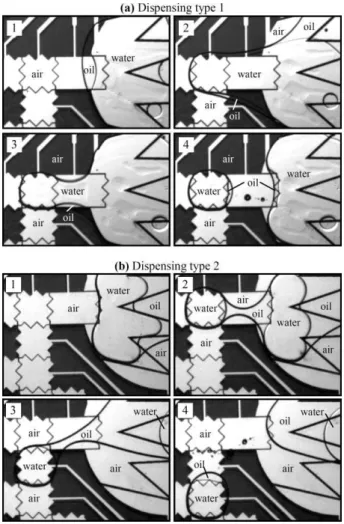
4.2. Dispensing
Fig. 4 illustrates the process of creating core–shell droplets on-chip from a larger reservoir. The reservoir is first filled with water and silicone oil in the desired proportions. As discussed in section 2.1, the oil then spontaneously forms a shell around the water in the reservoir. The creation of a core–shell droplet can then be performed with the same procedure as in air or in oil.1,5,6,19,23 A liquid protrusion is first created by activating the
two electrodes adjacent to the reservoir (Fig. 4a-2). During the formation of the liquid protrusion, the water drags the oil shell along. The first electrode is then turned off while the electrode of the reservoir is activated to break the liquid neck and form the core–shell droplet (Fig. 4a-3 and 4a-4). Thus, as seen in Fig. 4, the oil shell is spontaneously transferred from the reservoir to the core-shell droplet during the dispensing process.
On the other hand, depending on the operation conditions, two different types of dispensing were observed in the core– shell configuration. In the first type, illustrated in Fig. 4a, both the water core and the oil shell of the droplet are created at once during the dispensing. In the second type, illustrated in Fig. 4b, the water core is created first and remains attached to the reservoir by a silicone oil neck. The silicone oil neck can then be broken by moving the droplet away from the reservoir (Fig. 4b-3 and 4b-4). This second type of dispensing has several drawbacks for the operation of EWOD-based devices. Indeed, the oil neck shown in Fig. 4b can pull the water droplet back in the reservoir and can sometimes stretch across a large number of electrodes before breaking. Also, the first type of dispensing typically leads to thinner oil shells, which is desirable to avoid the formation of oil spots behind the core-shell droplets (as discussed in section 4.1).
We found that the second type of dispensing is favored by either (i) filling the reservoir with a large amount of silicone oil or (ii) a low operation voltage. A thicker oil shell is indeed more difficult to break along with the water during the dispensing. Also, a low operation voltage causes the liquid neck to break more slowly, which favors the accumulation of silicone oil in the neck region before the creation of the droplet. At very low voltages, the electrowetting forces were found to be too weak
Fig. 4 Time lapse sequences (from 1 to 4) showing in (a) and (b) the two types of dispensing observed in the core-shell configuration. (a) In dispensing type 1, the water core and the oil shell of the core–shell droplets are created at once. (b) In dispensing type 2, the water core is created first and remains attached to the reservoir by a silicone oil neck.
to break simultaneously the water–oil and the oil–air interfaces. Indeed, as shown in Table 2, the first type of dispensing could only be obtained at an operation voltage above 48 V, while a voltage of 38 V is sufficient to separate only the water phase from the reservoir without breaking the oil neck. On the other hand, the threshold voltage for dispensing is found to be much higher in air than for either types of core-shell dispensing.
Table 2 Threshold voltages required to perform various fluidic opera-tions in the EWOD-based devices for droplets actuated in air, in oil and in the core-shell configuration
Threshold voltages
Operation Air Oil Core–shell Actuation 65 V 25 V 30 V 25 mm s−1velocity 80 V 65 V 52 V
50 mm s−1velocity 90 V — 65 V
100 mm s−1velocity 98 V — 82 V
Droplet dispensing 70 V 38 V 48 V (type 1) 38 V (type 2) Droplet splitting 90 V 52 V 60 V
4.3. Merging, mixing, and splitting
Fig. 5 shows the merging, mixing, and splitting of two core-shell droplets. Merging is achieved simply by transporting the two droplets to the same electrode. As shown in Fig. 5b, the oil shells are seen to merge first, thus leading to the formation of a double core droplet. In our devices, the two cores were found to merge spontaneously a fraction of a second later (Fig. 5c). The mixing of the two cores could then be achieved by transporting the droplet across several electrodes (i.e., by using the same procedure as in air or in oil).1,9,10On the other hand, as shown
in Table 2, different threshold voltages are required to split apart the droplets depending on the configuration. Splitting is most easily performed in oil due to the low contact line friction achieved in this configuration and the relatively low water–oil interfacial tension (∼35 mN m−1). On the other hand, splitting
was found to be extremely difficult to perform in air and could only be achieved at operation voltages near the onset of contact angle saturation (i.e., at ∼90 V; see Fig. S1 in ESI†). For core– shell droplets, the threshold voltage for splitting is found to be only marginally higher than in oil. This slight increase can be attributed to the oil–air interface which, despite its rather low interfacial tension (17.4 mN m−1), can increase the force
required to deform and break the core–shell droplets during the splitting process. On the other hand, the measured threshold voltages confirm that the core–shell configuration provides a very interesting alternative to reduce the operation voltage of EWOD-based digital microfluidic devices for applications where the presence of an oil medium is not acceptable.
Fig. 5 Time lapse sequence showing (a–c) the merging, (d) the mixing, and (e–f) the splitting of two core-shell droplets. The core of the top droplet was dyed with rhodamine B.
Conclusions
In this work, we proposed and investigated an alternative mode of operation for EWOD-based digital microfluidic devices in which the aqueous droplets are enclosed in a thin silicone oil shell. The various characteristics of this core–shell configuration were reviewed and compared with the traditional approach
where the droplets are manipulated directly in air or silicone oil. We demonstrated the possibility to perform on-chip all the fundamental fluidic operations with core–shell droplets. We also found that, in the proposed configuration, low contact line friction and low viscous drag can be achieved simultaneously, which offers several advantages in terms of operation voltage and actuation speed. Indeed, the voltage required for droplet manipulation was found to be much lower in the core–shell configuration than in air. Our results additionally showed that core–shell droplets can be actuated at significantly higher velocity than water droplets manipulated in either air or oil. The configuration proposed herein should thus offer an increased flexibility toward the realization of high-throughput and high reliability EWOD-based digital microfluidic devices.
Acknowledgements
This work was supported financially by the Natural Sciences and Engineering Research Council of Canada and the National Research Council of Canada.
References
1 R. B. Fair, Microfluid. Nanofluid., 2007, 3, 245–281. 2 S. Haeberle and R. Zengerle, Lab Chip, 2007, 7, 1094–1110. 3 M. G. Pollack, R. B. Fair and A. D. Shenderov, Appl. Phys. Lett.,
2000, 77, 1725–1727.
4 M. G. Pollack, A. D. Shenderov and R. B. Fair, Lab Chip, 2002, 2, 96–101.
5 M. G. Pollack, Ph.D. Thesis, Duke University, Durham, NC, USA, 2001.
6 S. K. Cho, H. J. Moon and C. J. Kim, J. Microelectromech. Syst., 2003, 12, 70–80.
7 H. Moon, S. K. Cho, R. L. Garrell and C. J. Kim, J. Appl. Phys., 2002, 92, 4080–4087.
8 R. B. Fair, A. Khlystov, T. D. Tailor, V. Ivanov, R. D. Evans, P. B. Griffin, V. Srinivasan, V. K. Pamula, M. G. Pollack and J. Zhou,
IEEE Des. Test Comput., 2007, 24, 10–24.
9 P. Paik, V. K. Pamula and R. B. Fair, Lab Chip, 2003, 3, 253– 259.
10 P. Paik, V. K. Pamula, M. G. Pollack and R. B. Fair, Lab Chip, 2003,
3, 28–33.
11 A. R. Wheeler, H. Moon, C. J. Kim, J. A. Loo and R. L. Garrell,
Anal. Chem., 2004, 76, 4833–4838.
12 T. Xu, P. Thwar, V. Srinivasan, V. K. Pamula and K. Chakrabarty,
IEEE/NIH Life Science Systems and Applications Workshop, 2007,
pp. 140–143.
13 H. Moon, A. R. Wheeler, R. L. Garrell, J. A. Loo and C.-J. Kim,
Lab Chip, 2006, 6, 1213–1219.
14 A. R. Wheeler, H. Moon, C. A. Bird, R. R. O. Loo, C. J. Kim, J. A. Loo and R. L. Garrell, Anal. Chem., 2005, 77, 534–540.
15 J. Y. Yoon and R. L. Garrell, Anal. Chem., 2003, 75, 5097–5102. 16 H. Ren, R. B. Fair, M. G. Pollack and E. J. Shaughnessy, Sens.
Actuators, B, 2002, 87, 201–206.
17 E. S. Baird and K. Mohseni, Nanoscale Microscale Thermophys. Eng., 2007, 11, 109–120.
18 S. K. Cho, Y. Zhao and C.-J. C. Kim, Lab Chip, 2007, 7, 490– 498.
19 H. Ren, R. B. Fair and M. G. Pollack, Sens. Actuators, B, 2004, 98, 319–327.
20 V. Srinivasan, V. K. Pamula and R. B. Fair, Lab Chip, 2004, 4, 310– 315.
21 V. Srinivasan, V. K. Pamula and R. B. Fair, Anal. Chim. Acta, 2004,
507, 145–150.
22 Y. H. Chang, G. B. Lee, F. C. Huang, Y. Y. Chen and J. L. Lin,
Biomed. Microdevices, 2006, 8, 215–225.
23 R. B. Fair, A. Khlystov, V. Srinivasan, V. K. Pamula and K. N. Weaver, Lab-on-a-Chip: Platforms, Devices, and Applications,
24 Z. Guttenberg, H. M ¨uller, H. Haberm ¨uller, A. Geisbauer, J. Pipper, J. Felbel, M. Kielpinski, J. Scriba and A. Wixforth, Lab Chip, 2005,
5, 308–317.
25 A. Renaudin, P. Tabourier, J.-C. Camart and C. Druon, J. Appl. Phys., 2006, 100, 116101.
26 D. Beyssen, L. L. Brizoual, O. Elmazria and P. Alnot, Sens. Actuators,
B, 2006, 118, 380–385.
27 O. D. Velev, B. G. Prevo and K. H. Bhatt, Nature, 2003, 462, 515–516. 28 J. R. Millman, K. H. Bhatt, B. G. Prevo and O. D. Velev, Nat. Mater.,
2005, 4, 98–102.
29 T. P. Hunt, D. Issadore and R. M. Westervelt, Lab Chip, 2007, 8, 81–87.
30 J. Z. Chen, S. M. Troiana, A. A. Darhuber and S. Wagner, J. Appl.
Phys., 2005, 97, 014906.
31 A. A. Darhuber, J. P. Valentino, S. M. Troian and S. Wagner,
J. Microelectromech. Syst., 2003, 12, 873–879.
32 U. Lehmann, S. Hadjidj, V. K. Parashar, C. Vandevyver, A. Rida and M. A. M. Gijs, Sens. Actuators, B, 2006, 117, 457– 463.
33 Z.-G. Guo, F. Zhou, J.-C. Hao, Y.-M. Liang and W.-M. Liu, Appl.
Phys. Lett., 2006, 89, 081911.
34 K. Mohseni and E. S. Baird, Nanoscale Microscale Thermophys. Eng., 2007, 11, 99–108.
35 Y. Y. Lin, C. W. Lin, L. J. Yang and A. B. Wang, Electrochim. Acta, 2007, 52, 2876–2883.
36 I. Moon and J. Kim, Sens. Actuators, A, 2006, 130, 537– 544.
37 A. Kajiwara, K. Suzuki, H. Miura and H. Takanobu, Proc. 23rd
Sensor Symposium, 2006, 201–204.
38 R. A. Hayes and B. J. Feenstra, Nature, 2003, 425, 383–385. 39 F. Mugele and J.-C. Baret, J. Phys.: Condens. Matter, 2005, 17, R705–
R774.