Publisher’s version / Version de l'éditeur:
Materials and Structures, 44, 1, pp. 13-28, 2010-05-01
READ THESE TERMS AND CONDITIONS CAREFULLY BEFORE USING THIS WEBSITE. https://nrc-publications.canada.ca/eng/copyright
Vous avez des questions? Nous pouvons vous aider. Pour communiquer directement avec un auteur, consultez la
première page de la revue dans laquelle son article a été publié afin de trouver ses coordonnées. Si vous n’arrivez pas à les repérer, communiquez avec nous à [email protected].
Questions? Contact the NRC Publications Archive team at
[email protected]. If you wish to email the authors directly, please see the first page of the publication for their contact information.
NRC Publications Archive
Archives des publications du CNRC
This publication could be one of several versions: author’s original, accepted manuscript or the publisher’s version. / La version de cette publication peut être l’une des suivantes : la version prépublication de l’auteur, la version acceptée du manuscrit ou la version de l’éditeur.
For the publisher’s version, please access the DOI link below./ Pour consulter la version de l’éditeur, utilisez le lien DOI ci-dessous.
https://doi.org/10.1617/s11527-010-9605-9
Access and use of this website and the material on it are subject to the Terms and Conditions set forth at
Mechanical properties of calcium silicate hydrates
Alizadeh, R.; Beaudoin, J. J.; Raki, L.
https://publications-cnrc.canada.ca/fra/droits
L’accès à ce site Web et l’utilisation de son contenu sont assujettis aux conditions présentées dans le site LISEZ CES CONDITIONS ATTENTIVEMENT AVANT D’UTILISER CE SITE WEB.
NRC Publications Record / Notice d'Archives des publications de CNRC:
https://nrc-publications.canada.ca/eng/view/object/?id=60d6403a-eb80-4342-9e6c-f8801ebdb430 https://publications-cnrc.canada.ca/fra/voir/objet/?id=60d6403a-eb80-4342-9e6c-f8801ebdb430
http://www.nrc-cnrc.gc.ca/irc
M e c ha nic a l prope rt ie s of c a lc ium silic a t e hydra t e s
N R C C - 5 3 5 2 2
A l i z a d e h , R . ; B e a u d o i n , J . J . ; R a k i , L .
M a y 2 0 1 0
A version of this document is published in / Une version de ce document se trouve dans:
Materials and Structures, 44, (1), pp. 13-28, May 01, 2010, DOI: 10.1617/s11527-010-9605-9
The material in this document is covered by the provisions of the Copyright Act, by Canadian laws, policies, regulations and international agreements. Such provisions serve to identify the information source and, in specific instances, to prohibit reproduction of materials without written permission. For more information visit http://laws.justice.gc.ca/en/showtdm/cs/C-42
Les renseignements dans ce document sont protégés par la Loi sur le droit d'auteur, par les lois, les politiques et les règlements du Canada et des accords internationaux. Ces dispositions permettent d'identifier la source de l'information et, dans certains cas, d'interdire la copie de documents sans permission écrite. Pour obtenir de plus amples renseignements : http://lois.justice.gc.ca/fr/showtdm/cs/C-42
Mechanical Properties of Calcium Silicate Hydrates
Rouhollah Alizadeh*, James J. Beaudoin and Laila RakiInstitute for Research in Construction, National Research Council of Canada
The dynamic mechanical properties of compacted samples of synthetic calcium silicate hydrate (C-S-H) were determined at variable stoichiometries (C/S ratio). The stiffness and damping properties of the C-S-H systems were monitored at various increments of mass loss from 11%RH following the removal of the adsorbed and interlayer water. The changes in the storage modulus (E’) and internal friction (tan δ) were discussed in terms of the state of water present in the nanostructure of C-S-H, the evolution of the silicate structure and the interaction of calcium ions in the interlayer region. Results were compared to that for the hydrated Portland cement paste and porous glass. It was shown that the C-S-H in the hydration products of Portland cement has a complicated yet analogous dynamic mechanical behavior to that of synthetic C-S-H. The response of these systems upon the removal of water was explained by a layered model for the C-S-H. A mechanistic model was proposed to describe the changes occurring at various stages in the dynamic mechanical performance of C-S-H.
Keywords: Dynamic Mechanical Analysis, Calcium Silicate Hydrate (C-S-H), Hydrated
1. Introduction
Calcium Silicate Hydrate (C-S-H)*, the principal product of the Portland cement hydration
process, is a major contributor to the important mechanical properties of hardened cement paste such as strength and shrinkage [1]. The nanostructure and mechanical properties of this material have not been clearly understood and the link between chemical composition, microstructure and the mechanical behavior of C-S-H is still ill-defined despite many experimental and modeling studies [2].
It has been argued that the interlayer water present between the layers of C-S-H plays an important role in controlling its mechanical properties [3]. It has been shown that the removal of water molecules in the interlayer region results in significant reduction of the length and modulus of elasticity (E) of hydrated Portland cement [4, 5]. It has been suggested that water molecules occupying the interlayer space can act as a “reinforcement” to the C-S-H layer [4]. Several experiments on the change in the modulus of elasticity (E) at various relative humidity levels indicate that a significant reduction in the value of E occurs when the saturated Portland cement paste is equilibrated at relative humidity levels below about 11% [3, 6]. The humidity at these levels is associated with the interlayer water in addition to a monolayer of water present on the surface of particles. There is about a 40% decrease in the modulus of elasticity in this region determined by static or dynamic methods as shown in Figure 1. A structural role was assigned to the interlayer water in these studies. It is inferred that reduction in stiffness in this region cannot be simply due to the microcracking as suggested by Odelson et. al. [7]. It has been shown that there is a hysteresis in the modulus of elasticity versus relative humidity curves of the hydrated cement paste [3-5]. The drying cycle consistently has the trend indicated in Figure 1 (i.e. a large decrease in E at humidity levels below 11%RH). On rewetting the E values can increase by as much as 100%. If there was any significant amount of micro-cracking in the specimens during the first drying, the E values in the second and subsequent drying cycles would have continued to decrease gradually and thereafter would not have shown a sudden decrease as in the first drying cycle. Estimation of the changes in the stiffness of cement paste due to other phenomena involving the solid phase such as collapse of the C-S-H layers when interlayer water is removed and possible cross-linking of silicates has received little attention. There is a lack of detailed information for the variations in the elastic response of C-S-H systems in this region (i.e. below 11%RH). This is the focus in the current work.
1.1. Characteristics of C-S-H in Portland Cement Paste
The C-S-H that forms in the hydration of Portland cement has variable stoichiometry depending on the water to cement ratio, curing conditions and use of supplementary cementitious materials [8]. It is therefore important to understand the effect of compositional changes on the different properties of C-S-H systems. The studies in this regard have been mainly conducted on the synthetic C-S-H materials due to the ease in controlling their chemical composition. Characterization of properties such as modulus of elasticity, creep and strength, however, has been rarely conducted systematically on synthetic or phase pure C-S-H. The main parameter that controls the formation of various
* Cement chemistry nomenclature: C=CaO, S=SiO
synthetic C-S-H structures is the starting molar ratio of CaO to SiO2 (C/S ratio). The
dependence of the mechanical properties of C-S-H on the C/S ratio has received only limited study. It was shown that the intrinsic modulus of elasticity (E0, zero porosity value)
appears to be independent of the C/S ratio and degree of silicate polymerization [9]. The mechanical properties of the C-S-H in cement paste were also studied by a nano-indentation technique [10]. It was suggested that two types of C-S-H exist in hydrated Portland cement; low density and high density, having a volume fraction of 30 and 70%, respectively. The nanoindentation results showed that the low-density C-S-H phase has a mean stiffness of about 22 GPa while the mean stiffness is about 29 GPa for high-density C-S-H [11]. These two types of C-S-H identified through mechanical measurements are likely to be compositionally similar. The difference in the modulus of elasticity, therefore, is essentially due to the level of particle packing and change in the porosity at lower scales as suggested by the nanoindentation studies. It was also shown that the intrinsic modulus of elasticity of the C-S-H phase can be reduced through decalcification (more significant for the low density C-S-H) and this appears to be the main factor in the degradation of elastic modulus at the macroscopic level.
Plassard et al. employed nanoindentation methods (using Atomic Force Microscopy) to measure the elastic modulus of C-S-H formed on the surface of a calcite crystal in sodium silicate solution [12]. The C-S-H produced was equilibrated at various concentrations of calcium hydroxide solution in order to achieve different stoichiometries. It was shown that the elastic modulus increases at higher Ca2+ contents with an inflection point at a concentration of about 8 mmol/L (corresponding to a C/S ratio of 1.1 [13]) suggesting a phase transition. It was also proposed that silanol-water-silanol bonds (source of interlayer cohesion) are replaced by SiO−−Ca2+−SiO− bonds when C/S ratio increases causing a
reduction in the interlayer space and an increase of the compactness that in turn improves the modulus of elasticity.
The elastic properties of C-S-H have also been estimated through dynamic molecular modeling and free energy minimization techniques [14]. These methods were primarily used in order to evaluate the stability of the structural models of Hamid [15] and Merlino
et al. [16] for tobermorite systems. The simulated values suggest that the average Young
modulus can increase from 63.5 to 89 GPa consistent with the increase in C/S ratio from 0.83 to 1.0. The interlayer distance was found to be very important for these mechanical changes.
It has been also suggested that the attractive electrostatic forces active at short and medium ranges contribute essentially to the cohesion of C-S-H [17]. The mechanical properties of crystalline C-S-H systems were also investigated using lattice dynamic simulations [18]. Calculations indicated that the Young’s modulus values (although very scattered) decrease slightly when the C/S ratio increases. High modulus values (compared to experimental results) were computed for various C-S-H systems similar to other theoretical studies [14, 18]. An increase in the mean silicate chain length in tobermorite systems was also shown to result in an increase of the modulus. A silicate structure containing defects was therefore suggested as a possible reason for the discrepancy of the theoretical and experimental results. The source of the cohesion forces in synthetic C-S-H and C-S-H formed in cement paste has not been definitively determined. Although van der Waals and capillary forces partially contribute to the cohesion of such materials [19], the major factor that keeps the layers stable is associated with the iono-covalent properties of chemical bonds in the interlayer. In this situation, calcium ions and water molecules are strongly localized [14].
In the current study, dynamic mechanical properties of phase pure C-S-H compacts prepared at various C/S ratios are determined. The variation in the stiffness and damping characteristics of C-S-H upon the removal of adsorbed and interlayer water is discussed. The role of water molecules on the C-S-H surface and in the interlayer region, the nanostructural changes in the silicate structure and the interactions of ions in the interlayer space on the removal of water are considered as possible mechanisms contributing to the mechanical performance of C-S-H. Results for synthetic C-S-H are compared to those for the C-S-H in hardened cement paste and porous glass. An attempt is made to relate the local order and composition of C-S-H systems to some of their macroscopic mechanical properties. Additional evidence supporting the view that the properties of synthetic layered C-S-H are analogous to those for C-S-H present in the Portland cement paste is presented and discussed. A mechanistic model is proposed for the changes in the mechanical behavior of C-S-H (variable composition) at various stages of drying. The hydrated Portland cement systems may contain a wide range of C-S-H phase compositions depending on the mixture proportions and curing conditions. This makes it difficult to assess the contribution of each phase to the mechanical performance of hardened cement paste. The results from this study using phase pure C-S-H therefore offer evidence to better understand the nature of the C-S-H phases and the role of water in their nanostructure. This should also help improve modeling the mechanical properties of hydrated Portland cement at the micro and nano-level.
2. Experimental Procedure
2.1. Materials
C-S-H was synthesized from the pozzolanic reaction of amorphous SiO2 and CaO in
excess water. Reactive silica (CAB-O-SIL®, grade M-5 from Cabot Corporation) was
heated at 110°C to remove any surface adsorbed water. Reagent grade calcium carbonate (Sigma-Aldrich company) was calcined at 900 °C to obtain calcium oxide. Distilled water was de-aired and used for the reactions. All materials were kept in sealed N2 purged bottles
until used. Various C-S-H systems were prepared using stoichiometric amounts of CaO and SiO2 in order to produce samples having C/S ratios of 0.8, 1.0, 1.2 and 1.5. This range
of C/S ratio fits in the category of C-S-H (I) proposed by Taylor [8]. The materials were first dry-mixed and shaken manually in 1L high-density polyethylene (HDPE) bottles. Water was then added to the mixture (water/solid≈10). The bottles were mounted on a rotating rack. They were rotated (at the speed of 16 rpm) along the axis perpendicular to their symmetric axis and the reaction continued for 6 months. The chemical reaction is nearly completed in the first week, but further time is required to obtain a well-ordered crystalline structure. The material was filtered after this period and dried under vacuum for 4 days at room temperature. The dried C-S-H samples (in the form of powder) were stored in nitrogen purged glass vials before experiments. During these steps maximum care must be taken to avoid or minimize the exposure of the material to the atmosphere. In such conditions a surface carbonation may occur on the C-S-H due to the CO2 in the air. TGA
analysis of the final product confirmed the purity of the C-S-H samples from Ca(OH)2 and
CaCO3.
Two other sets of samples were prepared for comparison purposes: cement paste and porous Vycor® glass. Rectangular prisms (250x100x12 mm) were cast from the Portland
were vibrated and stored in a moist curing room for 24 hours. They were then demoulded and curing was continued for 2 months in a saturated lime solution. Thin slices (~1x12x60 mm) were cut from the cement prism using an Isomet diamond saw. The cooling agent was saturated lime solution in order to avoid calcium leaching. Vycor porous glass plates (thickness=1.3 mm, surface area=110 cm2/g, porosity~ 28%) were cut to give rectangular
specimens measuring 12x60 mm. The length of the specimens was chosen according to the standard requirements of the three point bending test [20, 21].
2.2. Humidity Conditioning
The C-S-H powders, cement paste slices and porous glass were conditioned for three weeks in a vacuum desiccator over the vapor pressure of a saturated lithium chloride solution. This gives a relative humidity of about 11% at room temperature which is a good base for studying the stoichiometry of C-S-H [22]. There is, theoretically, only a monolayer of adsorbed water on the surface of particles at this specific humidity in addition to the interlayer water. This moisture state was used as the starting condition of the experiments. C-S-H compact bars were therefore prepared from the 11%RH conditioned powder.
2.3. Preparation of compacted C-S-H samples
A rigid body of the material is required for any type of investigation of mechanical properties such as dynamic mechanical analysis. In Portland cement hydration studies, the cement paste hardens in the mould and can be cut into various shapes depending on the type of the test. It is, however, necessary to prepare solid samples by compressing the fine powder for the studies on powdered materials such as synthetic C-S-H, in order to measure the mechanical properties [23, 24]. In addition, it is possible to extend the range of porosity and avoid some of the limitations inherent in the use of natural rigid porous materials. It has been shown that the compacted specimens of powdered hydrated Portland cement have similar properties to that of original hardened paste of the same sample [4, 25, 26]. The bonds between the particles in a compacted cement sample essentially mimic those that form during the setting and hardening of cement. The bringing of the surface of particles together primarily involves the formation of van der Waals’s attractions. Solid-state reactions can also be postulated. The mechanical properties of compacted C-S-H powder specimens are considered analogous to those of the C-S-H in cement paste.
In the compaction technique, the steel mould is first mounted vertically with the bottom piston. The powder is then placed in the cylinder having a rounded rectangular cross section. The mould is then struck by a rubber hammer on its sides in order to level the surface of the powder. This is very important in achieving a uniform thickness throughout the compacted specimen. The top piston is then placed in the cylinder and the assembly is mounted in a compression machine. The pressure is increased gradually to a specified value where it is maintained for about 30 seconds before releasing. The compaction pressure was applied manually. The compacted specimen was removed by pressing out the pistons.
In order to have useful and reliable DMA data a recommended range of sample thickness has to be used according to the experimental specifications. Through a trial and error
process, the mass of the C-S-H powder was varied so that the thickness of the bar resided within the limits of 0.6 to 3.0 mm suggested for each individual C-S-H compact bar (depending on its complex modulus of elasticity calculated after the initial tests). It was decided to use two grams of powder from each composition in order to satisfy the thickness requirements and simplify the procedure. Also, the length of the sample has to be 10% more than the space between the supports on both sides and the thickness should not vary more than 2% of the mean value along the length of the sample [20, 21].
The different C/S ratio C-S-H powders (conditioned at 11%RH) were compacted in order to make rectangular solid bodies. Four compact bars were prepared for each C/S ratio applying different compaction pressures. The porosity-pressure dependence had been determined before the experiments for each specific C/S ratio and was used as a calibration. In order to determine the porosity-pressure dependence, compacts of two grams of C-S-H (for each C/S ratio) were prepared at four different compaction pressures (80, 200, 358 and 518 MPa). The porosity of the compacted sample was determined using a helium pycnometer. The latter provides a measure of the solid volume in the sample. Porosity is calculated knowing the apparent volume and the solid volume of the compacted sample. The porosity-pressure curves can be fit with an exponential equation. The pressure required to produce a compact having a porosity value of 30% was obtained from the pressure-porosity curves for each C/S ratio and used in the preparation of a separate set of samples for the study on the effect of the removal of water on the mechanical behavior of C-S-H. The pressure applied for each C-S-H sample was 496, 517, 331 and 438 MPa, respectively, for the C/S ratio = 0.8, 1.0, 1.2 and 1.5 in order to obtain a porosity of about 30%. At this relatively low porosity level there is a sufficiently large fraction of the solid material that comes to play to better represent the behavior of the C-S-H. This volume fraction of pores is also desired since the hydrated Portland cement paste (w/c=0.40) and porous glass had porosity values of 26% and 28%, respectively. A length of 60 mm was cut from the middle of the rectangular compact bars to fit the specimen requirements in the DMA testing instrument. The thickness varied between 0.8 and 1.2 mm depending on the C/S ratio and the compaction pressure. It is essential to compare the mechanical properties of various C-S-H compositions, cement paste and porous glass in a similar porosity range. Porosity is an important parameter in controlling the mechanical performance of solids. The variation in the other factors influencing the mechanical characteristics of C-S-H can therefore be evaluated almost independently of their total pore volume.
2.4. Dynamic Mechanical Analysis (DMA)
In this technique the displacement of the sample is measured when an oscillating force is applied [27]. The stiffness of the material is calculated from the deformation under load. The elastic property obtained in DMA is called the storage modulus (E’) that is analogous to the static modulus of elasticity. There is also often a time lag between the applied force and the resulting displacement. The time lag can be measured as a phase angle between load and the displacement due to their ideally sinusoidal nature. The tangent of this angle (tan δ) represents the material’s damping property or internal friction.
The DMA analysis was conducted using a Rheometrics RSA II instrument on the C-S-H, cement paste and porous glass samples starting from 11%RH condition. The test was conducted on the same specimen after incremental drying at various mass loss levels. The removal of water was achieved by the application of a combination of vacuum and heat in
a special drying cell. Maximum care was taken in the sample treatment. The combination of vacuum and heat was applied over a long period of time in order to avoid any physical damage to the samples. The initial mass loss levels were obtained only through vacuum at room temperature. The temperature was gradually increased and only exceeded 50 °C at mass loss values above 8%. Obtaining the last couple of data points without applying higher temperatures (but below 110 °C) was inevitable. This did not affect the oscillatory nature of the E’/tan δ – mass loss curves (discussed later). The sample was mounted on the three point bending apparatus shown in Figure 2. A very low amplitude oscillation was applied on the brittle thin samples (~1 mm thick) in order to prevent any damage or microcracking. This was confirmed by a microscopic analysis after the experiment. Moreover, no decrease was observed in E’ value when a trial specimen was repeatedly subjected to the same loading procedure. Samples were tested at a frequency of 0.1Hz for displacement. The original experiments were conducted in the frequency range from 0.1 to 10 Hz. It was observed that the E’ and tan δ-mass loss curves had similar features at all frequencies. The oscillatory trend in the E’ and tan δ (section 3.2) was observed at all frequencies and was independent of the moisture content. The intensity of the peaks in the curves, however, was decreased by increasing the frequency. The data for the lowest frequency (0.1 Hz) was, therefore, reported here in which the variations were more distinguishable.
A strain of 0.01% (in the elastic region) was applied with an initial static load of 20 g in order to ensure a good contact between the upper fixture and the surface of the specimen throughout the dynamic loading. The induced stress was below 2 MPa which is low enough not to introduce any significant damage or micro-cracking to the sample. The initial values might be set differently for various samples depending on their response to the load. Before conducting the experiments, the calibration of the equipment was checked using the standard weights and a steel bar. The response of the sample was recorded and analyzed by the RSI orchestrator computer software.
3. Results and Discussion
3.1. Dynamic mechanical properties versus porosity
The results of the E’ (storage modulus), and tan δ (internal friction) are presented in the Figure 3 for various C-S-H preparations (C/S=0.8 to 1.5) compacted to different porosity levels. The data variation in this set of results is about ±5%. A set of tests was also conducted on Portland cement paste and porous glass for comparison. In all C-S-H samples, the storage modulus (E’, shown in Figure 3(a)) decreases as the porosity increases as expected [9]. The regression curves are well separated based on their C/S ratio for all specimens except C/S=0.8 at porosity value of 23% which exhibits lower E’. This was reproduced several times and seems to be due to the compaction limitations. At higher porosity levels the values of E’ for C/S=0.8 are greater than the other C/S ratios. Low C/S ratio C-S-H that can be prepared through decalcification of the cement paste [11, 28] or equilibrating the synthetic C-S-H in low lime content solutions [12] was shown to have lower stiffness compared to the starting material. This, however, is not in contradiction with our observations of high elasticity values at lower C/S ratios (at the same porosity). It may suggest that the governing factor in the decalcification of the paste is the increase in the porosity level of the solid due to the leaching of calcium out of the material. Current work utilizes careful sample preparation in order to compare the mechanical properties of various C-S-H compositions at the same porosity – an important parameter in controlling
the mechanical behavior of materials. It is also possible that the decrease of strength after calcium depletion might be due to other microstructural changes in the solid body such as microcracking. Low C/S ratio C-S-H has a greater degree of polymerization and longer silicate chains. It is suggested that the continuity of the solid phase is improved for C-S-H compacts having lower C/S ratio. Longer silicate chains may better “reinforce” the Ca-O backbone of the C-S-H sheet. This may augment the stiffness of the material. Consistent results have been recently obtained using dynamic molecular modeling of the C-S-H suggesting that the chain length of the silicate tetrahedra is directly related to the modulus value [29].
Values of E’ for C/S=1.0 are greater at all porosities than C-S-H specimens with C/S ratio greater than 1.0. The storage modulus of the C/S=0.8 C-S-H sample appears to be distinctly different than other samples. This may suggest that low C/S ratio C-S-H can fall in a different category. This is also supported by 29Si NMR investigation and other
techniques [30-34]. In general, it is suggested that the silicate polymerization of the C-S-H enhances its elastic properties.
It is possible to estimate the intrinsic storage modulus of the cement-based materials using the proposed empirical equations that correlate various mechanical properties with the porosity [35-38]. The relation proposed by Helmuth and Turk [35] can not be applied as it was developed for the saturated state. Another equation has been adopted from the studies in ceramic science [36, 37] and has been used in the investigation of cement systems [38] to relate the modulus of elasticity (E) and porosity (P) as follows:
bP e E
E = 0 − (1)
where E0 is the Young’s modulus at ‘zero porosity’ and b is a constant. An analogous
equation can be used for the correlation of storage modulus (E’) with porosity obtained in the current study. The following equation which is the linear form of the equation (1) was curve fitted to the data in Figure 3(a):
bP E
E')= ln( ' )−
ln( 0 (2)
The fitted parameters of E’0and b are presented in Table 1. A relatively reasonable fitting
of the equation to the data was obtained (average R2=0.98) which suggests that this
equation approximates well with the modulus values of compacted C-S-H samples. The zero porosity values of the storage modulus are in the order of the calculated theoretical elasticity values for C-S-H systems [14, 18]. It was observed that the E’0 increases at lower
C/S ratios similar to the behavior shown in Figure 3(a) (the value at P=23% was not considered in the calculations for C/S=0.8). The C-S-H having the two lower C/S ratio values (C/S=0.8 and 1.0) exhibits higher values of E’0. There is only a change in the order
of E’0 values between the C/S=1.2 and 1.5. The storage modulus of C-S-H C/S=0.8 is
considerably higher than that for the other samples. Using atomistic modeling calculations, it has been shown that the modulus of elasticity of the C-S-H increases with increasing the silicate chain length (which is inversely related to the C/S ratio) [29]. The constant parameter b (that is attributed to the pore geometry and orientation under stress [38]) appears to be independent of the C/S ratio. Its average value (0.052) is less than that for the
cement paste [39]. This parameter which is essentially the slope of the lines in log scale is similar for all C/S ratios, confirming alike pore structure of compacted C-S-H specimens.
The results for the internal friction of C-S-H compacts (a measure of the damping behavior of this material) are shown in Figure 3(b) versus the porosity of the specimens. For all C/S ratios, the internal friction increases with the decrease in the solid volume fraction of the specimens. The empty pore spaces in the solid body can be deformed easier under load than the solid part through which some energy is adsorbed. The presence of a larger amount of pores increases the chance of the sliding of solid grains and their friction against each other. This bulk effect may be responsible for the increase of the damping at higher porosity levels.
It is also observed that the internal friction increases with the increase in the C/S ratio for a given porosity (i.e. the C-S-H with C/S=0.8 has the lowest tan δ and C-S-H with C/S=1.5 has the highest value). This can possibly be due to the effect of silicate polymerization. At higher C/S ratio, the C-S-H is less polymerized and silicate chains are shorter. Therefore, for a similar amount of moles, high C/S ratio C-S-H material may have more individual units. This may increase the sliding sites available between particles in the C-S-H compact and result in higher internal friction. It should also be mentioned that tan δ and E’ act in opposite directions in cement-based materials [40-43], i.e. when the elasticity of the specimen decreases, the damping increases and vice versa. This is consistent with the results of this study (Figure 3) that show the order of the tan δ curves in terms of their C/S ratio is almost the inverse of that for E’. It is also noted that the tan δ values for C/S=1.2 and 1.5 are very close, similar to the observation for their E’ values. The curve for C/S=1.0 then separates samples from the low lime content C-S-H (C/S=0.8). It appears that the C/S=0.8 falls in a different category as its DMA response is very distinct from that of other C-S-H samples.
The DMA test was also conducted on a thin slice of cement paste (W/C=0.4) and porous glass both previously conditioned at 11%RH. The results for these specimens are plotted based on their porosity for comparison with the C-S-H curves in the same graph (Figure 3). The E’ and tan δ values of the cement paste are almost of the same order of magnitude as for C-S-H samples although these single values are not conclusive as to any similarity with a specific C/S ratio. The main part of study with synthetic C-S-H is concerned with the role of water in its nanostructure in comparison with the cement paste and is discussed in the next section.
3.2. Role of adsorbed and interlayer water
The change in the dynamic mechanical properties of C-S-H as well as the cement paste and porous glass was followed on the incremental removal of water from these systems starting at the 11%RH condition. Several specimens were examined for each C/S ratio in order to study the dynamic mechanical performance of the C-S-H at various porosity levels. The current work reports only the results for the samples having the porosity value of about 30% (a relatively low value so that more solid material is present in the sample). Duplicates were also made for these samples at this porosity level. Duplicate samples do not necessarily have the same values for E’ and tan δ at a given mass loss level, but the trend used as the basis for understanding the nanostructural role of water is readily
reproduced. After each drying step (using vacuum and heat treatment), the dried sample was weighed (to calculate the amount of the mass loss) and was tested quickly. The sample was then returned to the drying cell for further removal of water.
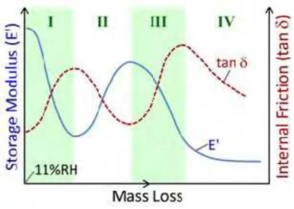
Each E’ and tan δ versus mass loss curve is attained using the same specimen in order to to avoid inconsistencies. These are semi-equilibrium curves that require sufficient time to obtain each mass loss level. About 7 to 10 days is required for testing each specimen in order to construct each E’ or tan δ – mass loss curve by collecting about 10-15 data points. This was considered sufficient for the investigations in the small humidity range below 11%RH. A work in progress by the authors explores the changes in the dynamic mechanical properties of C-S-H versus temperature. More than 80 data points were collected for each curve and the observed reproducible results confirm the oscillatory variations in the dynamic mechanical properties of C-S-H systems reported here. A TGA analysis at the end of the test showed a negligible amount of calcium carbonate in the rectangular samples. This confirms that the care taken was adequate to avoid any significant carbonation of the C-S-H. Moreover, the extent of carbonation would have been very limited due to the low humidity in the sample. The change in the micro- or nano-structure of the C-S-H upon the removal of water is the main point of interest in this part of the current study as it may bring insight to the nanostructural role of water in C-S-H. The behavior of C-S-H under dynamic loading at various humidity levels is unique. There are various steps in the DMA response of C-S-H upon the removal of water. These are illustrated in schematic shown in Figure 4 (stages I-IV). Tests showed reproducible oscillatory trends in the E’ and tan (δ). This behavior that was observed in many samples (variable porosity and chemical composition) appears to be ‘real’. The results of the E’ and tan δ measurements for C-S-H (C/S=0.8, 1.0, 1.2 and 1.5) at various mass losses from 11%RH are shown in Figure 5. As mentioned previously, both adsorbed water and interlayer water are present in 11%RH conditioned samples. The changes, therefore, can be discussed considering the role of water in these two states. The silicate structural changes in the C-S-H (as determined by 29Si NMR and helium inflow experiments on the same materials subjected to similar drying procedure) and interlayer calcium ions are also used to account for these observations.
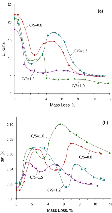
The changes in the storage modulus of C-S-H specimens are shown in Figure 5(a). All C/S ratio C-S-H samples depict a decrease in stiffness followed by a peak (i.e. they increase to a maximum) as they are dried to lower moisture contents. There are four distinct mass loss regions for each curve. In stage I, a significant initial decrease in E’ occurs (up to about 2% mass loss from the 11%RH condition). This steep reduction in the stiffness is attributed to the loss of adsorbed water and some of the interlayer water [26]. It has been shown that the drying of hydrated Portland cement paste results in significant reduction of the dynamic modulus of elasticity which might be attributed to the microcracking [44], dehydration of calcium silicate hydrate [45], or a combination of both [46]. Our tests were conducted on the compacts made from 11%RH conditioned C-S-H powders. Extreme care was also taken during gradual drying. The microcracking (that might be observed when a saturated paste is dried as opposed to the starting 11%RH condition in the current study) was not observed in the C-S-H samples as confirmed by microscopic analysis. Moreover, significant micro-cracking, if present, would have resulted in a continuous decrease in the storage modulus over the entire mass loss range. The fact that the E’ increases at a certain drying state suggests that the micro-cracking was not an issue. A very similar value for the E’ is reproduced when the C-S-H sample is repeatedly subjected to unloading and loading
at constant moisture content. A decrease in E’ should have been observed if there was significant micro-cracking. The changes therefore can be explained in terms of the dehydration of C-S-H itself. Water molecules ‘reinforce’ the silicate sheets and contribute to the stiffness of the C-S-H structure. The point of inflection on this part of the curve appears to be related qualitatively to the surface area of the C-S-H. About n monolayers of water (presented in Table 2) are lost at this drying level corresponding to the inflection point. The monolayer capacity of C-S-H samples and cement paste are calculated according to the following equation proposed by Powers and Brownyard [47]:
02 . 6 6 . 10 10 18 3 × × × = S − Vm (3)
where Vm is the monolayer capacity (grams per gram of dry paste) and S is the BET surface
area measured using nitrogen gas (m2/g).
It is suggested that the surface adsorbed water contributes to the stiffness of the C-S-H, the surface energy of which increases with the removal of this water. The inflection point in the stage I appears to occur at lower mass loss levels for higher C/S ratio. This type of C-S-H has a lower surface area and thus less capacity for adsorbing water molecules on the surface. It is possible that some interlayer water is removed simultaneously due to the overlap of the energy by which water is held at different structural locations (i.e. adsorbed and interlayer water). The plateau at the beginning of the curves is probably only due to the adsorbed water. The overall decrease in the storage modulus as water molecules are removed from the systems is not in agreement with the computational simulation for C-S-H systems [18].
An increase in E’ (stage II) begins to occur at a mass loss of about 2-3% for all C-S-H compositions. Such an increase in the stiffness of cement based materials has not previously been reported. The change in the elasticity of Portland cement paste, for example, only depicts a significant decrease for the humidity levels in this region [3, 6]. Drying of C-S-H results in an increase in the degree of polymerization and possible cross-linking of the silicate chains [48-50]. Evidence for this is based on 29Si NMR observations (on the same material subjected to a similar drying procedure) where there is an increase in the Q2/Q1 ratio and some indication of the presence of a Q3 peak. It is, therefore, suggested
that the increase in the E’ might be a result of the interaction of silicates between the layers. The observed stiffening of C-S-H may also be explained by the role of calcium ions in the interlayer region. Partially dehydrated calcium ions interact specifically with the ≡Si-O– groups of the short silicate chains [51]. It has been suggested that covalent bonds
are created to some extent between the C-S-H sheet and the interlayer. This indicates the possibility of strong ‘surface-cation-surface’ ionic-covalent interactions. Calcium ions contribute to the electrostatic interaction between lamellae that is as strong as Si-O-Si chemical bonds [52]. Upon the drying of the C-S-H more calcium containing ions are dehydrated between the layers. This is likely to promote such ionic-covalent bonds and, in turn, improve the elasticity of C-S-H as observed by the increase in storage modulus in this work (Figure 5(a)). It is unlikely that the increase in the E’ is related to factors that are not concerned with the chemistry of the material. For example, one may suggest that the micro-cracking and subsequent healing is responsible for the initial decrease followed by the increase in E’. The issue of micro-cracking was ruled out before. Also, healing is unlikely to occur in the phase pure C-S-H systems as there is no un-hydrated material and free lime such as is the case for the hydrated cement paste. The observations in the
variations of E’ and tan δ, therefore, appear to be related to the nanostructural changes in the C-S-H upon the removal of water. The increase in the storage modulus tends to a maximum with mass loss followed by a further decrease. The decrease (stage III) is a result of the removal of the final quantities of interlayer water, which provide structural stability to the layered nanostructure. The decrease is analogous to what occurs on the drying of cement paste [40]. The rapid decrease in the basal spacing in this region of mass loss as observed for high C/S ratio C-S-H [53] suggests possible association of the decrease in E’ with a collapse mechanism of C-S-H structure. Removal of interlayer water molecules is critical to the structural integrity of the C-S-H framework.
It is difficult to compare the changes at various steps of water removal on the basis of the difference in the C/S ratio of the C-S-H. The starting point of the increase in E’ (stage II) does not follow any specific order based on the C/S ratio. The initiation and occurrence of the peak at this stage, however, seems to happen at lower mass loss levels for low C/S ratio samples (C/S=0.8 and 1.0). The population of Q2 sites is higher for low lime C-S-H
samples. The possibility of cross-linking between silicates may increase at these silicate sites. This is suggested as a possible mechanism for the increase in E’. The intensity of this peak is less pronounced for C/S=1.5. There are likely to be more Ca2+ ions in the interlayer region that may restrict the cross-linking of silicate sites between the layers although these ions may interact with the layers and improve the cohesion of C-S-H sheets when dehydrated.
The decline in the storage modulus (stage III) occurs faster for C/S=1.0. The E’ goes to a plateau (stage IV) after a mass loss of about 9% in all samples. This corresponds to a reduction of nearly 75% in the storage modulus as a result of the removal of adsorbed and interlayer water. Figure 5 is primarily intended to show that the C-S-H exhibits a complex dynamic mechanical response on the removal of adsorbed and interlayer water. The trend for this behavior is similar for all C-S-H preparations. The absolute values of E’ and tan δ for a given mass loss, however, cannot be conclusively compared between various C/S ratio C-S-H samples as this would involve excessive speculation. It also should be noted that the application of temperatures above 50 °C (but below 110 °C) is relevant only for the mass loss levels above 8% which has no effect on the oscillatory nature of the curves observed in the current study. Other microstructural aspects of the C-S-H such as the density may change at such relatively high temperature levels.
The changes in the tan δ (internal friction) for C-S-H samples are presented in Figure 5(b). The main parameter of interest in the current study that influences the tan δ is the moisture content. The data for tan δ was compared at the same frequency (0.1 Hz). The internal friction of C-S-H decreases at higher frequencies for a given moisture content (not shown), but the main features showing an oscillatory trend in tan δ and the peak locations remain the same. All curves can be separated into distinct regions of mass loss consisting of four stages that represent different damping behavior upon the removal of water from various nanostructural locations. In the first stage there is an increase in the internal friction. This part of the curve starts off with a plateau at the beginning (corresponding to the storage modulus results observed before) that is attributed mainly to the removal of the adsorbed water. Further drying results in the partial removal of the interlayer water although the bond energy associated with the presence of interlayer water in layered silicates is greater than that for surface adsorbed water [54]. This may increase the ability of the layers to translate since water molecules are considered to restrain the C-S-H sheets. More energy is, therefore, dissipated as observed by the increase in tan δ during the stage I. The stiffness of C-S-H is reduced (Figure 5(a)) during this period. The increase in the internal friction is
followed by a peak at about 2% mass loss which matches well with the end of stage I in the changes of storage modulus.
The descending portion (stage II) following the peak in tan δ is attributed to the initial cross-linking between silicate layers and increase in the polymerization. Increase in the interaction of calcium ions with the lamellae can be responsible as well. Bridging of the C-S-H sheets and an increase in the number of strong bonds (either Si–O–Si or ≡Si–O- –Ca2+)
reduces the damping behavior of C-S-H although it improves the stiffness of the material observed before. This portion of the curve ends at the same mass loss where a peak occurs in the storage modulus for each C/S ratio C-S-H (except C/S=1.5). Stage III in the tan δ shows an ascending behavior. This increase in damping might be due to the sliding of silicate layers as they have come closer to each other upon the removal of interlayer water. The peak observed following this stage corresponds to the end of third stage in storage modulus. The decline in damping (stage IV) after the second maximum is attributed to the removal of the remaining amount of interlayer water and possibly some constitutional water at higher mass losses. The co-occurrence of changes and simultaneous transitions in the E’ and tan δ has been previously observed in different investigations of the cement paste [41, 42]. Mechanisms responsible for these changes seem to have inverse effects on stiffness and damping.
Similar DMA tests were conducted on thin slices of hydrated Portland cement (w/c=0.4) conditioned at 11%RH. Variations in stiffness and damping of the cement paste on the removal of adsorbed and interlayer water were followed (Figure 6). There are several stages in the results that are analogous to the behavior of synthetic layered C-S-H explained before. When the cement paste is dried, a relatively significant decrease occurs in the storage modulus simultaneously with an increase of the internal friction. This stage, as described before, is when the adsorbed water and part of the interlayer water are removed from H. The second stage of changes and the peak in E’ (observed for C-S-H) are manifested by a plateau in the curve for the cement paste at about 2% mass loss. The C-S-H in cement paste is nearly amorphous and incorporates in its structure elements other than silicon such as aluminum. This may reduce the cross-linking potential and interaction of silicate sites in hydrated Portland cement that is a contributing mechanism to the increase in the stiffness of C-S-H. The first maximum and subsequent reduction of tan δ (stage II) is, however, more pronounced. A further decrease in the storage modulus simultaneously occurring with the formation of a second maximum in the internal friction for hydrated Portland cement corresponds well with similar behavior in the synthetic C-S-H. Collapse of the silicate layers and removal of the remaining water molecules are likely to contribute to these variations. The hydrated Portland cement contains phases other than C-S-H such as calcium hydroxide. The DMA response is thus not exactly the same as that for the synthetic phase pure C-S-H. The trend in the E’ and tan δ for the cement paste was reproduced several times. In other words, the initial sharp decrease in E’ followed by a short period (at about 1.5-3% mass loss) where the rate of decrease is minimal and a further gradual decrease of the E’ were repeatedly obtained in the DMA experiments on several samples. The E’ versus mass loss curve for the cement paste has more subtle features than the curve for the C-S-H and does not exhibit a peak at about 4-5% mass loss. The case for the tan δ-mass loss curve is much clearer. This reproducibility was obtained for the double peaks in the tan (δ)-mass loss curve. These variations correspond well with those for the synthetic C-S-H. This complex behavior (specifically that in the tan δ) can be explained by considering the similar nanostructural features for the C-S-H in OPC to that of the layered synthetic C-S-H.
The similar trend in the DMA response of hardened cement paste to that in the layered semi-crystalline C-S-H is a new evidence for the layered nature of the C-S-H in hydrated Portland cement and the structural role for the water within its structure. The magnitude of the changes in the E’ and tan δ for cement paste is not as high as those for the synthetic C-S-H. There is only about a 25% reduction in the storage modulus when the sample is completely dried. The average internal friction is also about 15% of that for phase pure C-S-H. It is suggested that this is due to the fact that the C-S-H in the hydration products of Portland cement is significantly less crystalline and has a more disordered structure. The changes are therefore not very pronounced yet comparable to the behavior of more crystalline-layered phases. There are also other hydration products in the cement paste that reduce the C-S-H content and therefore diminishe the variations contributed by the C-S-H phase. The complex DMA response of the cement paste upon drying was qualitatively reproduced several times using different samples.
Radjy and Richards showed that heat treatment of cement paste using temperatures up to 100 °C (that essentially results in the removal of water from various locations including interlayer water) decreases the modulus of the cement paste [43]. The range of E’ and tan δ and the extent of their variations corresponds well with the results presented here. They, however, identified only one transition [42] and suggested that changes in the internal friction are not significant and that the values are “essentially constant”. Careful examination of the results of their work (Figure 2 in Ref. [43]), however, reveals a similar pattern to the results of this study (Figure 5(b)) having two maximum in the tan δ upon drying. A parallel comparison of the results for cement paste with synthetic C-S-H in our study supports assigning physical meanings to these peaks that might seem to be experimental fluctuations at first. The reduction in modulus values decreased following the second and third drying [43]. This irreversible transition was called a “surface area” transition. It is suggested that the observed behavior is mainly due to the irreversible role of interlayer water. The cement paste treated at higher temperatures has been characterized by DMA [55, 56]. The heating of cement paste did not reveal any significant change in tan δ and only a gradual decrease was observed in the modulus due to the dehydration of C-S-H. It should be noted that drying in these studies was conducted dynamically as there was a continuous increase in the temperature. The work reported here, however, employs a different method of drying including several hours of vacuum and heat treatment for each data point at a constant temperature that allows us to obtain at least a semi-equilibrium humidity condition in the samples.
The change in the elasticity of porous glass on the drying from 11%RH is shown in Figure 6. The stiffness of porous glass is considerably less that that of the cement paste at this humidity level. The moisture content is also very low and the maximum amount of evaporable water is only about 2% of the mass at this state which is essentially adsorbed on the surface. Removal of this water slightly decreases the storage modulus value. The tan δ values (not shown) were very scattered.
3.3. A Mechanistic Model for C-S-H
Considering that the complex dynamic mechanical response of Portland cement paste is analogous to behavior of the layered semi-crystalline C-S-H, a nanostructural model is proposed to explain various steps in the change in the elasticity and internal friction of C-S-H. This model incorporates features of both physical [57, 58] and composition-based
[59-61] models for C-S-H in order to explain the changes in the elasticity and damping of calcium silicate hydrates (shown schematically in Figure 4) with respect to the contributions from water and silicates. The authors contend that the globule model [57] is not able to explain the experimental observations in this study unless a ‘layered concept’ is introduced with an assignment of structural role to the interlayer water. The globule model recognizes the layered nature of the individual globules or particles. The model, as shown in Figure 7, considers a layered structure for the C-S-H in the hydration products of Portland cement. Water molecules can be adsorbed on the surface and be present in the interlayer space at the starting 11%RH condition (Figure 7(a)). The silicate chains (varying in length and number of defects depending on their C/S ratio) and the calcium ions in the interlayer are features of this model.
As water molecules are removed by drying from the surface of the C-S-H and partially from the interlayer space (Figure 6(b)), a significant decrease in the elasticity occurs. Layers of C-S-H are still separated at this stage and the internal friction increases during this period. Possible cross-linking (either Si-O-Si or Si-O–Ca–O-Si bonds) as well as a slight decrease in the basal spacing occur when more interlayer water is removed (Figure 6(c)). This is responsible for the decline in tan δ and increase of the stiffness. Collapse of the C-S-H structure after this stage provides more sliding sites and increases the internal friction but reduces the elasticity (E’). The dehydration of the C-S-H through further removal of water molecules in the interlayer region (Figure 6(d)) decreases damping behavior and brings modulus values to a plateau.
4. Conclusions
Various C-S-H compositions (C/S=0.8 to 1.5) and hydrated Portland cement specimens were characterized for their dynamic mechanical behavior at 11%RH condition. It was shown that the mechanical properties of C-S-H are dependent on its C/S ratio. There is a decrease in the storage modulus (E’) as well as an increase in the internal friction (tan δ) as the C/S ratio of the C-S-H increases. A unique multi-stage change in the stiffness and damping of C-S-H similar to cement paste was observed as samples were conditioned to moisture contents lower than that in the 11%RH. It is suggested that adsorbed and interlayer water contribute significantly to the dynamic mechanical properties of C-S-H. Water molecules in the interlayer region act as restraints to the silicate structure. Mechanisms at the nano level such as collapse of the C-S-H structure, cross-linking of silicate sites and the interaction of dehydrated interlayer calcium ions with the silicate structure possibly contribute to the variations in E’ and tan δ at various drying stages. The C-S-H in the hydrated Portland cement has a complicated yet analogous dynamic behavior to that of synthetic C-S-H with respect to the role of water in various nanostructural locations. The synthetic C-S-H, therefore, can be considered as a viable nanostructural model for the mechanical property studies of the C-S-H in cement paste.
Acknowledgement
Authors would like to acknowledge the financial support from NSERC and the technical advice from Ms. Ana Delgado for the DMA analysis.
References
[1] T. D. Ciach, J. E. Gillott, E. G. Swenson and P. J. Sereda, “Microstructure of calcium silicate hydrates,”
Cement and Concrete Research, 1,13-25, 1971.
[2] Constantinides G. and Ulm F.-J., “The nanogranular nature of C-S-H,” Journal of Mechanics and Physics of Solids, 55, 64-90, 2007.
[3] Ramachandran, V.S., Feldman, R.F., Beaudoin, J.J., Concrete Science: Treatise on Current Research, London, U.K.: Heydon & Son Ltd. pp. 427, 1981.
[4] Feldman, R.F., “Factors affecting the Young's modulus - porosity relation of hydrated Portland cement compacts,” Cement and Concrete Research, 2(4) 375-386, 1972.
[5] Feldman, R.F., “Sorption and length-change scanning isotherms of methanol and water on hydrated portland cement,” Proceedings of the 5th International Symposium on the Chemistry of Cement, V. 3, Tokyo, Japan, 53-66, 1968.
[6] Sellevold E., personal communication, 2003.
[7] Odelson J.B., Kerr E.A. and Vichit-Vadakan W. “Young’s modulus of cement paste at elevated temperatures,” Cement and Concrete Research, 37, 258-263, 2007.
[8] Taylor H. F. W., Cement Chemistry, Thomas Telford, 2nd edition, London, 1997.
[9] Beaudoin J. J., Feldman R. F., “Dependence of degree of silica polymerization and intrinsic mechanical properties of C-S-H on C/S ratio,” 8th
International Congress on the Chemistry of Cement, Brazil, V. 3, 337-342, 1986.
[10] Constantinides G. and Ulm F.-J., “The effect of two types of C-S-H on the elasticity of cement-based materials: Results from nanoindentation and micromechanical modeling,” Cement and Concrete Research, 34, 67-80, 2004.
[11] Constantinides G., Ulm F. -J. and Van Vliet K. ,“On the use of nanoindentation for cementitious materials,” Materials and Structures, 36(3), 191-196, 2003.
[12] Plassard C., Lesniewska E., Pochard I., Nonat A., “Investigation of the surface structure and elastic properties of calcium silicate hydrates at the nanoscale,” Ultramicroscopy, 100, 331-338, 2004. [13] Steinour H. H., “The reactions and thermochemistry of cement hydration at ordinary temperature,” 3rd
International Symposium on the Chemistry of Cements, 261-289, 1954.
[14] Pellenq R. J.-M., Gmira A., Van Damme H., “Stability and elastic properties of tobermorite, a model of cement hydrate at the nano-scale,” MS&T’07, Advances in Cement-Based Materials, Detroit, Michigan, 1-12, September 2007.
[15] Hamid S.A., “The crystal structure of the 11 Å natural tobermorite Ca2.25[Si3O7.5(OH)1.5].1H2O,”
Zeitschrift fur Kristallographie, 154, 189-198, 1981.
[16] Merlino, S., Bonaccorsi, E., Armbruster, T., “Tobermorites: their real structure and OD character,” Amer. Mineral., 84, 1613-1621, 1999.
[17] Gmira A., Zabat M., Pellenq R.J.-M. and Van Damme H. “Microscopical basis of the poromechanical behaviour of cement-based materials,” Materials and Structures, 37, 3-14, 2004.
[18] Manzano H., Dolado J.S., Guerrero A. and Ayuela A. “Mechanical properties of crystalline calcium-silicate-hydrates: comparison with cementitious C-S-H gels,” Phys. Stat. Cal. (a), 204(6) 1775-1780, 2007.
[19] Pellenq R. J.-M., Van Damme H., “Why does concrete set? The nature of cohesion forces in hardened cement-based materials,” MRS Bulletin, 29(5), 319-323, 2004.
[20] ASTM D 5023-01 “Standard test method for plastics: dynamic mechanical properties: in flexure (three point bending),” American Society for Testing and Materials.
[21] ISO 6721-5, “Plastics-Determination of dynamic mechanical properties-Part 5: flexural vibration-Non-resonance method,” International Organization for Standardization.
[22] Feldman, R.F., Ramachandran, V.S. “A study of the state of water and stoichiometry of bottle- hydrated Ca3SiO5,” Cement and Concrete Research, 4(2), 155-166, 1974.
[23] Sereda P. J., Feldman R. F. “Compacts of powdered material as porous bodies for use in sorption studies,” J Applied Chemistry, 13, 150-158, 1963.
[24] Beaudoin J. J., “Comparison of mechanical properties of compacted calcium hydroxide and Portland cement paste systems,” Cement and Concrete Research, 13, 319-324, 1983.
[25] Soroka. I. and P J. Sereda. “The Structure of Cement-stone and the Use of Compacts as Structural Models.” 5th International Symposium on the Chemistry of Cement, Tokyo, 67-73, 1968.
[26] Sereda P. J., Feldman R. F., Swenson E. G., “Effect of sorbed water on some mechanical properties of hydrated Portland cement pastes and compacts,” Highway Research Board, Special Report 90, 58-73, 1966.
[27] Menard K. P., Dynamic Mechanical Analysis – A practical introduction, CRC Press LLC, pp. 208, 1999.
[28] Carde, C., François, R. “Effect of the leaching of calcium hydroxide from cement paste on the
mechanical and physical properties,” Cement and Concrete Research, 27(4) 539-550, 1997.
[29] Manzano H., Dolado J.S., Ayuela A. “Elastic properties of the main species present in Portland cement pastes,” Acta Materialia, 57, 1666-1674, 2009.
[30] M. Grutzeck, A. Benesi, and B. Fanning, ‘‘Silicon-29 magic-angle spinning nuclear magnetic resonance study of calcium silicate hydrates,’’ J. Am. Ceram. Soc., 72, 665-668, 1989.
[31] Klur I., Pollet B., Virlet J., Nonat A., “C-S-H structure evolution with calcium content by multinuclear NMR,” 2nd International conference on NMR spectroscopy of cement based materials, 119-141, 1998.
[32] Garbev K., Stemmermann P., Black L., Breen C., Yarwood J., Gasharova B., “Structural features of C– S–H(I) and its carbonation in air- A Raman spectroscopic study. Part I: Fresh phases,” J. Am. Ceram. Soc., 90(3), 900-907, 2007.
[33] Nonat A., Lecoq X., The structure, stoichiometry and properties of C-S-H prepared by C3S hydration
under controlled condition, NMR Spectroscopy of Cement Based Materials, edt. Colombet, A. R. Grimmer, H. Zanni, P. Sozzani, Springer-Verlag, Berlin Heidelberg, 197-207, 1998.
[34] Alizadeh R., Beaudoin J.J., Ramachandran V.S. and Raki L. “Applicability of Hedvall effect to study the reactivity of calcium silicate hydrates,” Journal of Advances in Cement Research, in press, doi:10.1680/adcr.2008.00008, 2008.
[35] Helmuth R.A. and Turk D.H., “Elastic moduli of hardened Portland cement and tricalcium silicate pastes: effect of porosity,” Symposium on Structure of Portland Cement Paste and Concrete (Special
Report 90), Highway Research Board, Washington, D.C. 135–144, 1966.
[36] Knudesn F. P. “Dependence of Mechanical Strength of Brittle Polycrystalline Specimens on Porosity and Grain Size,” Journal of the American Ceramic Society, 42(8), 376-387, 1959.
[37] Nielsen L. F. “Elasticity and Damping of Porous Materials and Impregnated Materials,” Journal of the American Ceramic Society, 67(2) 93-98, 1984.
[38] Beaudoin J. J., Feldman R. F., Tumidajski P. J. “Pore structure of hardened Portland cement pastes and its influence on properties,” Advanced Cement Based Materials, 1, 224-236, 1994.
[39] Beaudoin J. J. and Feldman R. F. “A study of mechanical properties of autoclaved calcium silicate systems,” Cement and Concrete Research, 5, 103-118, 1975.
[40] Radjy F. and Richards C.W. “Effect of curing and heat treatment history on the dynamic mechanical response and the pore structure of hardened cement paste,” Cement and Concrete Research, 3, 7-21, 1973.
[41] Sellevold E.J. and Radjy F. “Drying and resaturation effects on internal friction in hardened cement pastes,” J American Ceramic Society, 59(5-6), 256-258, 1976.
[42] Radjy F. and Richards C.W. “Internal friction and dynamic modulus transitions in hardened cement paste at low temperatures,” Materials and Structures, 2(7), 17-22, 1969.
[43] Radjy F. and Ricahrds C.W. “Effect of curing and heat treatment history on the dynamic mechanical response and the pore structure of hardened cement paste,” Cement and Concrete Research, 3, 7-21, 1973.
[44] Evans R. H. and Marthe M. S. “Microcracking and stress-strain curves for concrete in tension,” Matériaux et Constractions, 1, 61-64, 1968.
[45] Parrott L. J. “The effect of moisture content upon the elasticity of hardened cement paste,” Proceedings of the Fifth International Symposium on the Chemistry of Cement, Tokyo, V.3, 1-32, 1973.
[46] Haque M. N. and Cook D. J. “The effect of water sorption on the dynamic modulus of elasticity of desiccated concrete materials,” Materials and Structures, 9(6), 407-410, 1976.
[47] Powers T. C. and Brownyard T. L. “Studies of the physical properties of hardened Portland cement paste – Part 3: Theoretical interpretation of adsorption data,” Journal of the American Concrete Institute, 18(4), 469-504, 1946.
[48] Young J. F., “Investigations of Calcium Silicate Hydrate Structure Using Silicon-29 Nuclear Magnetic Resonance Spectroscopy,” J. Am. Ceram. Soc., 71(3) C118-C120, 1988.
[49] Yu P., Kirkpatrick R. J. “Thermal dehydration of tobermorite and jennite,” Concrete Science and Engineering, 1, 185-191, 1999.
[50] Sato H., Grutzeck M. “Effect of starting materials on the synthesis of tobermorite,” Mat. Res. Soc. Symp. Proc., vol. 245, 235-240, 1992.
[51] Van Damme H. and Gmira A. “Cement Hydrates” Chapter 13.3 in Handbook of Clay Science, Edited by Bergaya F, Theng B.K.G and Lagaly G., Elsevier Ltd., pp. 1246, 2006.
[52] Pellenq R.J.-M., Lequeux N., Van Damme H., “Engineering the bonding scheme in C–S–H: The iono-covalent framework,” Cement and Concrete Research, 38, 159-174, 2008.
[53] Mitchell L., Alizadeh R., Whitfield P., Beaudoin J. J. “Phases changes in semi-crystalline synthetic calcium-silicate-hydrate,” Submitted to Cement and Concrete Composites, pp. 1-17, 2009.
[54] Seligman P., “Nuclear magnetic resonance studies of the water in hardened cement,”Journal of the PCA
Research and Development Laboratories, Portland Cement Association, 10(1), 52-65, 1968.
[55] Morlat R., Godard P., Bomal Y. and Orange G. “Dynamic mechanical thermoanalysis of latexes in cement paste,” Cement and Concrete Research, 29, 847-853, 1999.
[56] Foray-Thevenin G., Vigier G., Vassoille R. and Orange G. “Characterization of cement paste by dynamic mechanical thermo-analysis,” Materials Characterization, 56, 129-137, 2006.
[57] Feldman R. F. and Sereda P. J., “A model for hydrated Portland cement paste as deduced from sorption-length change and mechanical properties,” Matériaux et Construction, 1(6) 509-520, 1968.
[58] Jennings H. M., “Refinements to colloid model of C-S-H in cement: CM-II,” Cement and Concrete Research, 38, 275–289, 2008.
[59] Cong X. and Kirkpatrick R. J., “29Si MAS NMR Study of the Structure of Calcium Silicate Hydrate,”
Adv. Cem. Based Mat., 3, 144-156, 1996.
[60] Richardson I.G., Groves G.W., “Models for the composition and structure of calcium silicate hydrate (C-S-H) gel in hardened tricalcium silicate pastes,” Cem. Concr. Res., 22, 1001-1010, 1992.
[61] Taylor H.F.W., “Proposed structure for calcium silicate hydrate gel,” J. Am. Ceram. Soc., 69(6) 464-467, 1986.
Table 1. Zero porosity values of the storage modulus for C-S-H
C/S ratio E’0 (GPa) b
0.8* 231.3 0.052
1 132.4 0.050
1.2 94.9 0.052
1.5 115.1 0.053
* The value at P=23% was not considered in the calculations.
Table 2. Estimated monolayer capacity (Vm) of the C-S-H and cement paste samples
C/S ratio Nitrogen Surface Area (m2/g) Vm(g/g)* n
0.8 186 0.0520 0.3 1.0 29 0.0082 1.1 1.2 30 0.0084 1.2 1.5 52 0.0146 0.8 OPC (W/C=0.4) 40 0.0110 0.8
1mm 12mm 60mm 10 12 14 16 18 20 22 0 20 40 60 80 1 E, G P a P/P0, % 00 [3] [6]
Figure 1. Effect of water desorption on the modulus of elasticity of Portland cement paste (W/C=0.3 and 0.4
from Ramachandran et al. [3] and Sellevold [6], respectively).
Figure 2. Three-point bending setup for the dynamic mechanical analysis of rectangular bar specimens
0 5 10 15 20 25 30 20 30 40 50 60 70 80 E' , G Pa Porosity, % CP40 Porous Glass C/S=0.8 C/S=1.0 C/S=1.2 C/S=1.5 (a) 0.005 0.010 0.015 0.020 0.025 0.030 0.035 0.040 20 30 40 50 60 70 80 ta n ( δ) Porosity, % CP40 Porous Glass C/S=0.8 C/S=1.0 C/S=1.5 C/S=1.2 (b)
Figure 3. The DMA results (E’ and tan δ) for C-S-H samples (various C/S ratios and different porosities) at
11%RH compared with the hydrated Portland cement (CP40) and porous Vycor® glass: (a) storage modulus,
0 5 10 15 20 25 0 2 4 6 8 10 E' , G Pa Mass Loss, % 12 C/S=1.5 C/S=1.2 C/S=0.8 C/S=1.0 (a) 0.00 0.02 0.04 0.06 0.08 0.10 0 2 4 6 8 10 ta n ( δ) Mass Loss, % 12 C/S=1.0 C/S=0.8 C/S=1.5 C/S=1.2 (b)
Figure 5. The DMA response (E’ and tan δ) of C-S-H samples (C/S=0.8, 1.0, 1.2 and 1.5) subjected to
0.010 0.012 0.014 0.016 0.018 0.020 14 16 18 20 22 24 0 2 4 6 8 10 ta n (δ ) E' , G P a Mass Loss, % E', cement paste tan (δ), cement paste E', porous glass
Figure 6. Storage modulus and internal friction in the DMA analysis of Portland cement paste (W/C=0.4) and porous Vycor® glass.
Figure 7. Schematic presentation of the nanostructural changes occurring on the removal of adsorbed and interlayer water in C-S-H. Interacted silicate tetrahedra and calcium ions are shaded in different colors (c and d).