Publisher’s version / Version de l'éditeur:
Vous avez des questions? Nous pouvons vous aider. Pour communiquer directement avec un auteur, consultez la première page de la revue dans laquelle son article a été publié afin de trouver ses coordonnées. Si vous n’arrivez pas à les repérer, communiquez avec nous à PublicationsArchive-ArchivesPublications@nrc-cnrc.gc.ca.
Questions? Contact the NRC Publications Archive team at
PublicationsArchive-ArchivesPublications@nrc-cnrc.gc.ca. If you wish to email the authors directly, please see the first page of the publication for their contact information.
https://publications-cnrc.canada.ca/fra/droits
L’accès à ce site Web et l’utilisation de son contenu sont assujettis aux conditions présentées dans le site
LISEZ CES CONDITIONS ATTENTIVEMENT AVANT D’UTILISER CE SITE WEB.
Research Report (National Research Council of Canada. Institute for Research in
Construction), 2010-09-01
READ THESE TERMS AND CONDITIONS CAREFULLY BEFORE USING THIS WEBSITE.
https://nrc-publications.canada.ca/eng/copyright
NRC Publications Archive Record / Notice des Archives des publications du CNRC :
https://nrc-publications.canada.ca/eng/view/object/?id=869babc8-3fa4-4b85-802b-05a07d280e5e https://publications-cnrc.canada.ca/fra/voir/objet/?id=869babc8-3fa4-4b85-802b-05a07d280e5e
NRC Publications Archive
Archives des publications du CNRC
For the publisher’s version, please access the DOI link below./ Pour consulter la version de l’éditeur, utilisez le lien DOI ci-dessous.
https://doi.org/10.4224/20374024
Access and use of this website and the material on it are subject to the Terms and Conditions set forth at
Characterization of Fires in Multi-suite Residential Dwellings: Phase 1 -
Room Fire Experiments with Individual Furnishings
http://www.nrc-cnrc.gc.ca/irc
Cha ra c t e riza t ion of Fire s in M ult i-suit e Re side nt ia l Dw e llings: Pha se 1
- Room Fire Ex pe rim e nt s w it h I ndividua l Furnishings
I R C - R R - 3 0 2
B w a l y a , A . C .
S e p t e m b e r 2 0 1 0
The material in this document is covered by the provisions of the Copyright Act, by Canadian laws, policies, regulations and international agreements. Such provisions serve to identify the information source and, in specific instances, to prohibit reproduction of materials without written permission. For more information visit http://laws.justice.gc.ca/en/showtdm/cs/C-42
Les renseignements dans ce document sont protégés par la Loi sur le droit d'auteur, par les lois, les politiques et les règlements du Canada et des accords internationaux. Ces dispositions permettent d'identifier la source de l'information et, dans certains cas, d'interdire la copie de documents sans permission écrite. Pour obtenir de plus amples renseignements : http://lois.justice.gc.ca/fr/showtdm/cs/C-42
Characterization of Fires in Multi-Suite
Residential Dwellings: Phase 1 - Room Fire
Experiments with Individual Furnishings
Research Report No. 302
Date: 15 September, 2010
Authors: Alex Bwalya, Eric Gibbs, Gary Lougheed, and
Ahmed Kashef
Institute for Research in Construction Fire Research Program
ii
Preface
This report describes a series of experiments conducted with various residential furnishings in a single-room test facility in the Characterization of Fires in Multi-Suite Residential Dwellings (CFMRD) project. The furnishings tested included mattresses, bed clothes, bed assemblies, upholstered seating furniture, clothing arrangements, books, plastic audio/video media and storage cases, toys and a computer workstation setup. Since the amount of data generated from the experiments is too extensive to be covered in a single comprehensive document, this report aims to: a) serve as the initial
documentation of the complete test series and, b) present results that supported certain decisions concerning the course of the experimental program. It is intended that additional results and analyses not presented herein will be covered in subsequent publications. The CFMRD project is a four-year collaborative research undertaking with industry,
provincial governments and city authorities that was initiated by NRC-IRC in 2006 to study fires in low-rise multi-suite residential dwellings of light-frame construction. The CFMRD project focuses on fires in dwellings, such as apartments, semi-detached houses, duplex houses, townhouses or row houses, secondary suites and residential care facilities. The main objectives of the project are:
1. To conduct fire experiments to characterize fires originating in various living spaces within multi-suite dwellings.
2. To conduct numerical simulations of various fire scenarios in order to interpolate and extend the data beyond that obtained in the experimental studies.
3. To produce a set of realistic design fires for multi-suite dwellings from the experimental data.
4. To develop an analytical method that can be used to calculate design fires for multi-suite dwellings.
The research approach employed by the project utilizes literature reviews, surveys to determine typical configurations and combustibles, computer simulations and fire experiments.
NRC-IRC gratefully acknowledges the financial and technical support of the Project Consortium, which consists of representatives from the following participating organizations:
• Canadian Automatic Sprinkler Association
• Canadian Concrete Masonry Producers Association • Canadian Furniture Manufacturers Association • The Canadian Wood Council
• City of Calgary • FPInnovations • Gypsum Association • Masonry Worx
• Ontario Ministry of Municipal Affairs and Housing • Régie du Bâtiment du Québec
• Ontario Ministry of Community Safety and Correctional Services (Office of the Fire Marshal)
iv
Abstract
Results are presented from a number of fire experiments that were conducted within a room environment to study the fire characteristics of typical residential furnishings and assist in the design of a subsequent phase of the project involving fully-furnished room fire experiments. The experiments were conducted in a 16 m2 test room (with dimensions 3.8 m wide x 4.2 m long x 2.4 m high) that had a 1.5 m x 1.5 m window opening. The
furnishings tested included mattresses, bed clothes, bed assemblies, upholstered seating furniture, clothing arrangements, books, plastic audio/video media and storage cases, toys, shoes and a computer workstation setup. The test room was instrumented with load cells, heat flux gauges, thermocouples and velocity probes in order to take the following measurements: mass loss, total heat flux on gauges installed flush with the internal surfaces (floor, walls and ceiling), temperatures at numerous locations and gas velocities in the window opening. The smoke from the room was collected using a hood system in order to measure the heat release rate (HRR) and optical density of the smoke.
Individual twin-size mattresses produced peak HRRs of approximately 3,800 kW and the maximum room temperature was approximately 980oC. The HRRs of bed assemblies of various sizes and configurations ranged from 1,800 kW for a twin bed, to 6,250 kW for a bunk bed. The maximum temperature and heat flux recorded in the experiments were 1,071oC and 221 kW/m2, respectively. Upholstered chairs and sofas had HRRs ranging from 630 kW for an Ottoman, to 3,360 kW for a two-seat sofa. Since the room dimensions and wall lining materials remained constant, temperatures were linearly proportional to the peak HRR (and exposure time) until the ventilation-limit (approximately 4,100 kW) was reached.
In tests with clothing, toys, shoes, books, computer workstation and CD/DVD media, the peak HRRs ranged from 440 kW for a bookcase to 2,045 kW for toys. Furnishings containing a large proportion of rigid thermoplastic plastics, such as shoes and media cases produced very dense smoke even at low HRRs.
CONTENTS
1 INTRODUCTION ... 1
1.1 Objectives ... 3
1.2 Experimental Approach ... 3
2 TESTSPECIMENS ... 5
2.1 Primary Combustible Furnishings (PCFs) ... 5
2.1.1 Mattresses ... 5
2.1.2 Bed clothes ... 7
2.1.3 Bed Assemblies ... 8
2.1.4 Upholstered Chairs ... 9
2.2 Secondary Combustible Furnishings (SCFs) ... 10
3 TEST FACILITY ... 11
3.1 Instrumentation ... 12
3.1.1 Data Acquisition System ... 13
3.2 Ignition Sources and Test Procedures ... 14
3.2.1 Test Procedures ... 15
3.3 Data Processing ... 16
3.3.1 Heat Release Rate ... 16
3.3.2 Optical Density ... 17
4 RESULTS AND DISCUSSION: PRIMARY COMBUSTIBLE FURNISHINGS ... 18
4.1 Selection of a Mattress ... 18
4.1.1 Conclusion ... 22
4.2 Additional Tests with Mattresses ... 22
4.3 Selection of Bed clothes ... 24
4.3.1 Conclusion ... 25
4.4 Bed Assemblies ... 25
vi
4.4.2 Effect of Bed Assembly Size and Other Parameters ... 28
4.4.3 Effect of Foundation and Flame-Resistant Mattress Design ... 32
4.4.4 Effect of Ventilation ... 35
4.5 Upholstered Chairs and Sofas ... 36
4.5.1 Chair Selection (Tests 9, 10, 15 and 26) ... 36
4.5.2 Effect of Chair Size ... 38
4.5.3 Ottoman and Futon Mattress ... 39
5 RESULTS AND DISCUSSION: SECONDARY COMBUSTIBLE FURNISHINGS (SCFS) ... 42
5.1 Clothing ... 42
5.2 Television Set ... 43
5.3 Books ... 44
5.4 CD/DVD Media, Shoes, Toys and Computer Workstation ... 45
6 CONCLUSIONS ... 47
7 ACKNOWLEDGMENTS ... 50
8 REFERENCES ... 51
Appendix A: Glossary ………54
Appendix B: Test Specimens – Photographs and Additional Details ………56
Nomenclature
Abbreviations Units
CRT Cathode ray tube
CS Ceiling surface
HC Effective heat of combustion (calorific value) (
MJ kg
/
)HRR Heat release rate (
kW
)N/A Not available (data) or Not applicable OD Optical density
OD/m Optical density per meter (OD/m) PCF Primary combustible furnishing
PUF Polyurethane foam SCF Secondary combustible furnishing SD Standard deviation from the mean
SI Single item -
TC Thermocouple
THR Total heat released (
MJ
)TV Television
Compass Directions
W West E East
viii S South N North NW North-West SW South-West Symbols
Q
′′
Radiant heat fluxkW
m
⎛ ⎞ ⎜ ⎟ ⎝ 2 ⎠T
Temperature (oC) T Average temperature (oC)T
∞ Ambient temperature (oC) mfQ
′′
Maximum heat flux at floor levelkW
m
⎛ ⎞
⎜ ⎟
⎝ 2 ⎠
mwc
Q
′′
Mean heat flux measured at walls and ceiling surfaces ⎛⎜ ⎞⎟⎝ ⎠
kW
m
2Subscripts
Max Maximum Min MinimumC
HARACTERIZATION OF
F
IRES IN
M
ULTI
-S
UITE
R
ESIDENTIAL
D
WELLINGS
:
P
HASE
1
-
R
OOM
F
IRE
E
XPERIMENTS WITH
I
NDIVIDUAL
F
URNISHINGS
by
Alex Bwalya, Eric Gibbs, Gary Lougheed and Ahmed Kashef
1 INTRODUCTION
This report presents the results of fire experiments that were conducted with various typical residential furnishings in a room environment in Phase 1 of a project titled “Characterization of Fires in Multi-Suite Residential Dwellings (CFMRD)”. The main objective of the CFMRD project is to characterize fires in residential dwellings and ultimately develop design fires and methods for use in fire safety engineering analysis and design. The results of this phase of the project were intended to help in the design of a series of full-scale fire experiments simulating various fully-furnished living areas in residential buildings in Phase 2 of the project. In this Phase of the project, 36 fire
experiments were conducted with various residential furnishings in a well-instrumented 16 m2 room (with dimensions 3.8 m wide x 4.2 m long x 2.4 m high) to capture the effect of radiation feedback and other room effects on fire behavior. The furnishings tested included mattresses, bed clothes, bed assemblies, upholstered seating furniture, clothing arrangements, books, plastic audio/video media and storage cases, toys and a computer workstation setup. The smoke from the room was collected using a hood system in order to measure the heat release rate (HRR).
For the purpose of this work, residential furnishings are divided into two broad groups: primary combustible furnishings (PCFs) and secondary combustible furnishings (SCFs). PCFs include items such as upholstered seating furniture and bed assemblies, which have long been recognized as the major combustibles that constitute the frequently-first-ignited items in many residential fires. SCFs consist of all other types of combustible contents, such as hard furniture, surface finishes (including flooring), clothing, paper and plastic articles that would be subsequently ignited at flashover and add fuel to a fire initiated by igniting a PCF. A glossary of terms used to describe upholstered furniture and components for bed assemblies, which will be used in this report, is given in Appendix A.
When PCFs are the first-ignited item, they are known to give rise to rapidly developing fires due to the flammability of the polyurethane foam (PUF) that is the dominant combustible constituent most
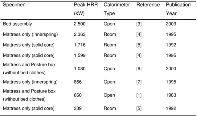
often used in their manufacture. As a result, a considerable amount of research has been conducted over the last three decades to characterize their fire behavior, develop predictive methods and to reduce their flammability. However, PCFs exhibit significant variations in their burning behavior as illustrated in Table 1 for mattresses. There has been more extensive fire
testing of mattresses than any other component of a bed since they contain the bulk of the PUF in a bed assembly. Peak HRRs of PCFs are known to vary widely and values greater than 3,000 kW have been reported in the literature [1, 2]. Among the PCFs, bed assemblies have perhaps the greatest multiplicity of configurations since there are many components that can be assembled around a mattress. For the purpose of a project such as this, it poses a problem in selecting suitable arrangement materials. In addition to the variations in the mattress design, other variables include foundations and bed clothes. Available options for bed clothes include various types of mattress pads (including ones with substantial PUF content), blankets, bed sheets and comforters, sleep pillows and decorator pillows, all of which have an influence on fire development.
Indeed, much data pertaining to experiments conducted with PCFs can be found in the literature. However, some of the data has limitations such as: the experiments were conducted in open calorimeters, which may not be appropriate for use in computer modelling of room fires since it excludes room effects; the data is outdated in the face of new materials and construction styles ushered in by technological changes and fashion trends; or some pertinent details of the
specimens, such as mass and material properties, are absent from the literature. In addition, there can be large variations in fire performance between different PCFs and different configurations of PCFs, as illustrated in Table 1. There are many reasons that contribute to these differences in fire performance, some of which are due to the variation in the quantity of polyurethane foam used in a particular mattress style or brand, and whether or not barrier fabrics or fire retardants have been used, resulting in much-reduced peak HRRs - of less than 1,000 kW, in some of the cases (shown in Table 1).
The main objective of the experiments in this Phase of the project was to evaluate the fire characteristics of various typical furnishings and to select a type of mattress and upholstered seating furniture to be used in full-scale experiments in fully-furnished rooms in Phase 2 of the project. The selection criteria that were adopted were inclined towards identifying PCFs, with realistic configurations, that would result in challenging fire scenarios in multi-family dwellings based on measures such as rate of fire growth, peak heat release rate and temperature levels in a room environment.
Table 1. Heat release rates of primary combustible furnishings. Specimen Peak HRR (kW) Calorimeter Type Reference Publication Year
Bed assembly 2,500 Open [3] 2003
Mattress only (Innerspring) 2,363 Room [4] 1995
Mattress only (solid core) 1,716 Room [5] 1992
Mattress only (solid core) 1,599 Room [4] 1995
Mattress and Posture box
(without bed clothes) 1,080 Open [6] 2000
Mattress only (innerspring) 866 Open [7] 1995
Mattress and Posture box
(without bed clothes) 660 Open [1] 1983
Mattress only (solid core) 339 Room [5] 1992
1.1 Objectives
1. Determine the combustion characteristics of a range of residential furnishings.
2. Select the types of PCFs (upholstered furniture, mattresses and bed assemblies) to be used in fully-furnished fire experiments.
1.2 Experimental Approach
Test specimens were selected to cover a number of combustible household items identified from a survey [8]. The experimental approach was structured to achieve the above stated
objectives. The underlying objective was to evaluate and determine combustion characteristics, such as HRR and calorific values, for single items of furniture or smaller groups of furnishings. The test specimens are referred to generally as Single Items (SI) since the experiments are similar to furniture calorimeter tests albeit in a room environment. To fulfill the second objective, a number of items of upholstered chairs and twin mattresses (and bed clothes) were purchased and tested in order to identify the types to be used as the first-ignited item in Phase 2 of the project. A multi-step experimental process was adopted in which a number of the items of upholstered chairs and
mattresses were tested during the first step. The results were analyzed and one type of upholstered chair and mattress was selected for further testing in different sizes and configurations during the subsequent steps. The steps of the experimental process are detailed as follows:
Upholstered Chairs:
• Step 1: Evaluate the combustion behavior of several types of chairs and select one type for further tests.
• Step 2: Evaluate the effect of size for one selected type of chair. This was achieved by testing two- and three-seat sofa1 versions of the selected chair.
Bed Assemblies:
• Step 1: The same as for chairs, but several types of mattresses were tested and one type was selected for further tests.
• Step 2: Compare the combustion behavior of various combinations of bed clothes. • Step 3: Test a bed assembly consisting of a mattress and bed clothes selected from
steps 1 and 2, and typical foundation (posture box or box spring).
• Step 4: Evaluate the effect of size (twin vs. double vs. queen) and configuration of the bed assembly (posture box vs. mate’s foundation vs. bunk configuration)
Other furnishings were selected on an ad hoc basis to represent typical items. The sequence of the tests was dictated by logistical factors relating to decision making time lines, for items requiring a selection process, and the need to limit any damage to the test facility. Therefore, items that were expected to have high HRRs were not tested in succession so as to avoid prolonged exposure of the test facility to high intensity fires.
1 A two-seat sofa is commonly known as a loveseat. In this report the word sofa is prefixed with “two-seat” or
2 TEST
SPECIMENS
In this study, it was essential that the furnishings used in the experiments were readily available in the market place to ensure continuity and to minimize variables. However, due to cost and fire initiation considerations, only PCFs and some SCFs, such as hard furniture items and plastic toys, were purchased in new condition from local furniture outlets. For PCFs, it was
important to purchase new items to minimize variables since the items selected in Phase 1 would be used as first-ignited items in Phase 2 of the project. However, in the case of clothing, stuffed toys, shoes and books, used items were purchased from local charities, since these would be expected to burn during the post-flashover period of a fire and therefore would have a minimal effect on the growth phase of a room fire initiated by igniting a PCF (bed assembly or sofa). Photographs of all the test specimens and other additional information, such as dimensions and material composition, are given in Appendix B. The list of test specimens is arranged in the order of testing (i.e. by test number). The composition of the materials was taken from manufacturer’s labels and no chemical analysis was conducted to verify the declared composition.
The following naming convention was adopted to identify tests and specimens: XX-SI-YY, where
XX is the test number and SI-YY is the specimen identification (ID) code; for example, 5-SI-03
refers to Test 5 conducted with specimen SI-03.
2.1 Primary Combustible Furnishings (PCFs)
2.1.1 Mattresses
Table 2 lists five twin-size mattresses, which were selected to represent a broad range of solid core and innerspring types that were available in the Canadian marketplace. Two of the mattresses (SI-01 and SI-04) were of solid core design whereas the rest were innerspring designs based on either the open coil or independent coil spring units. Since the amount of PUF contained in a mattress reflects its inherent fire hazard and, in general, the cost of a mattress increases with the PUF content, most of the mattresses selected were in the medium price range ($300 to $800) as these were found to incorporate substantial amounts of PUF when features such as pillowtops are added. However, one low cost mattress, SI-03, was also included to cover the lower end. As well, one mattress (SI-05) meeting an open flame test standard for mattresses, which was recently introduced in the U.S. was included in the test program. The test standard was codified as 16 CFR Part 1633 [9] (to be referred to as “16CFR1633” hereafter) and sets the following criteria to limit the growth of fire in a mattress or mattress set: a) the peak HRR must not exceed 200 kW within the
30 minutes of the test, and b) the total energy released must be less than 15 MJ for the first 10 minutes of the test.
At the time of conducting the experiments, there were no requirements for consumer mattresses sold in Canada to resist open flame ignition sources. Therefore, mattresses meeting the
flammability requirements of 16CFR1633 or California Technical Bulletin 603 [10] in the U.S. were not readily available in the Canadian marketplace. However, a voluntary test standard [11]
equivalent to the aforementioned U.S. test standards has been in effect since 2007 and, therefore future regulation of mattress flammability is possible.
Photographs of the mattresses and their internal structure (if available) are given in Appendix B. Table 2. Experiments with twin-size mattresses.
ID1 Test
Purpose2
Mattress Type Total Mass
(kg)
Thickness (m) Combustible Mass (kg)3
5-SI-03 S Innerspring 16.2 0.18 5.3 kg (33%)
6-SI-01 S solid core 12.5 0.22 12.5 kg (100%)
7-SI-02 S Innerspring 23.1 0.33 9.2 kg (40%)
8-SI-04 S Solid core 13.3 0.20 13.3 kg (100%)
14-SI-06 S Innerspring 17.8 0.31 10.5 kg (59%)
28-SI-05 I Innerspring 13.3 0.26 13.3 kg (100%)
35-SI-04 R Solid core 13.3 0.20 13.3 kg (100%)
1 Test and specimen identification code; 2 Objective of the test (S: Selection; I: Information; R: Repeat); 3
Estimated
The lower-priced mattress SI-03 (Figures B-1 and B-2; in Appendix B) had a similar internal
structure to SI-02 (Figures B-5 and B-6; In Appendix B), except that the upper padding consisted of thinner layers of PUF. Therefore, mattress SI-03 had the least amount of combustible materials as shown in Table 2. The nominal dimensions of the mattresses were 1.90 m long x 0.97 m wide, and thicknesses varied from 0.18 m to 0.33 m.
The innerspring mattresses typically consisted of an outer ticking followed by a layer of polyester fibers and a varying number of layers of PUF thereafter. In the case of mattresses SI-02 and SI-03, which used independent coil units, there was a layer of recycled cotton batting on the top and bottom of the coil unit.
2.1.2 Bed clothes
1 shows a list of tests conducted with various arrangements of bed clothes. All the tests were conducted with an inert mattress. The inert mattress was constructed by using an open coil spring unit wrapped in a ceramic fiber insulating blanket and covered with a non-combustible flexible woven safety blanket (36 oz. Agotex plus #1200-P) designed to resist temperatures of up to 1,500oC. Figures 1 and 2 illustrate the two types of arrangements of bed clothes, which were tested. In Setup #1 (Figure 1), the comforter and top sheet were not folded. In Setup #2 (Figure 2), the comforter and top sheet were folded back at a distance of 0.470 m from the head-side edge of the bed. Setup #1 was found to be the most common arrangement from survey results [12], whereas Setup #2 was adopted from another study [6]. The use of Setup #2 in most tests was partly influenced by the desire to compare results with that study [6].
Table 3. Test arrangements for bed clothes (twin-size).
Test no. ID Combinations of Bed clothes
(top to bottom arrangement)
Bed clothes Setup Total Mass (kg) 11 SI-08
Bed pillow (cover: 100% P; fill: 100% PF) Decorator pillow (cover: 100% P; fill: 100% PF) Comforter (cover: 60% P, 40% C; fill: 100% PF) Sheet set (100% C)
Skirt: 100% P
Mattress pad (cover: 60% P , 40% C; fill: 100% PF)
#2 6.7
12 SI-07
Bed pillow (cover: 70% P, 30% C, fill: 100% PF) Decorator pillow (cover: 100% P; fill: 100% PF) Comforter (cover: 60% P, 40% C; fill: 100% PF) Blanket (100% P)
Sheet set (100% C) Skirt: 100% P
Mattress pad (cover: 60% P , 40% C; fill: 100% PF) PUF mattress pad (topper): 100% PUF
#2 7.8
17 SI-75
Bed pillow (cover: 100% P; fill: 100% PF) Comforter (cover: 100% P; fill: 100% P) Sheet set (100% P)
Skirt (100% P); Platform: 100% PP
#2 4.6
19, 30 SI-83
Bed pillow (cover: 100% P; fill: 100% PF) Decorator pillow (cover: 100% P; fill: 100% PF) Comforter (cover: 50% P / 50% C; fill: 100% PF) Sheet set (60% P / 40% C)
Mattress pad (cover: 60% P , 40% C; fill: 100% PF)
#1 5.2
Abbreviations: C - Cotton; P - Polyester; PF – Polyester fibers; PP – Polypropylene; PUF – Polyurethane foam; Note: A sheet set consisted of a fitted sheet and a flat sheet.
Figure 1. Arrangement of bed clothes without folding back the comforter (Setup #1).
Figure 2. Arrangement of bed clothes with the comforter and top sheet folded back (Setup #2).
2.1.3 Bed Assemblies
Table 4 lists all the tests that were conducted with bed assemblies. All the bed assemblies used a posture box foundation except for Test 27, conducted with a mate’s bed foundation, and Test 42, which used an open-flame-resistant box spring. Test 42 was conducted with a mattress and foundation set, which was compliant with the 16CFR1633 test standard. However, the bed clothes used in Test 42 did not meet any flammability requirements.
Tests 34 and 44 were conducted to evaluate the effect of reducing the size of the window opening on fire development.
Table 4. Tests with Bed Assemblies (all using bed clothes comparable to SI-83).
Test no.
ID Size Mattress Bed clothes Foundation /
configuration Total Mass (kg)1 Window W x H (m)
21 SI-10 Twin SI-04 SI-83 PB 37.0 1.5 x 1.5
23 SI-76 Twin SI-06 SI-83 PB 40.4 1.5 x 1.5
27 SI-11 Twin SI-06 SI-83 Mate’s 86.5 1.5 x 1.5
29 SI-12 Double SI-06 SI-77 PB 53.8 1.5 x 1.5
31 SI-13 Queen SI-06 SI-78 PB 66.2 1.5 x 1.5
32 SI-14 Twin over
double SI-06 SI-77 / SI-83 Bunk 56.7 1.5 x 1.5
34 SI-12 Double SI-06 SI-77 PB 56.8 1.4 x 1.2
42 SI-85 Twin SI-05 SI-83 BS 42.5 1.5 x 1.5
44 SI-12 Double SI-06 SI-83 PB 53.9 1.4 x 1.2
Note: 1 Includes non-combustible mattress and foundation components, but excludes any supporting steel bed frame. PB: Posture box; BS: Box spring; Bunk: stacked beds fitted one on top of the other; Mate’s: Wood foundation with drawers.
2.1.4 Upholstered Chairs
Table 5 lists the upholstered chairs that were tested. None of the chairs had any indication that the upholstery materials contained any fire retardants and only chair SI-27 had a tag from the
Upholstered Furniture Action Council (UFAC) stating its conformance to the smouldering ignition test standard. The seat cushions were made of PUF slabs with a layer of polyester fiber batting between the cover fabric and the PUF, whereas the cushioning material in the backrests and arm rests consisted of polyester fiber batting only. All the frames of the chairs were made of wood. The mass of the frames was not determined.
The first four tests (nos. 9, 10, 15 and 26) were conducted in order to select a type of chair to be used in subsequent tests. Tests 40 and 41 were conducted with two-seat and three-seat sofa versions of the selected chair to evaluate the effect of size. An Ottoman (Test 36) and a Futon mattress (Test 43) were also tested to provide additional information.
Table 5. Tests with upholstered seating furniture.
Test No. ID Size Description Fabric Total Mass (kg)
9 SI-25 Chair 100% Polyester 30.8
10 SI-24 Chair 100% Polyester
microfibers
33.6
15 SI-27 Chair 51% Acrylic,
49% Polyester
12.2
26 SI-26 Chair 40% Acrylic;
60% Polyester
32.9
36 SI-29 Ottoman N/A 12.6
40 SI-31 Two-seat sofa 40% Acrylic;
60% Polyester
44.3
41 SI-32 Three-seat sofa 40% Acrylic;
60% Polyester
55.6
43 SI-33 Futon Unknown 17.0
2.2 Secondary Combustible Furnishings (SCFs)
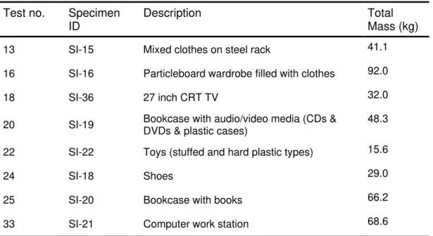
Table 6Error! Reference source not found. lists eight experiments that were conducted with various SCFs.
Table 6. Tests with Secondary Combustible Furnishings. Test no. Specimen
ID
Description Total Mass (kg)
13 SI-15 Mixed clothes on steel rack 41.1
16 SI-16 Particleboard wardrobe filled with clothes 92.0
18 SI-36 27 inch CRT TV 32.0
20 SI-19 Bookcase with audio/video media (CDs &
DVDs & plastic cases)
48.3
22 SI-22 Toys (stuffed and hard plastic types) 15.6
24 SI-18 Shoes 29.0
25 SI-20 Bookcase with books 66.2
3 TES
F which wa facility is sheet-me was erec construct 0.406 m o with a sin two layer attached 0.0127 m Figure 3. calorimet The inter wide x 4. represen construct in Figure series of sizes [13 is approxST FACIL
igure 3 show as located in given in a s etal hood wit cted on a conted with plyw o.c, was use ngle layer of rs of 0.0159 to the ceilin m cement bo
CFMRD tes ter test facilit rior dimensio 20 m deep b t the averag ted so that th 3, and the d preliminary , 14]. The th ximately 4,06
LITY
ws a photogr side a large eparate pub th a vertical ncrete slab u wood sheath ed for the wa cement boa m thick Typ g joists. The ard. st room and ty.ons of the tes by 2.38 m hi ge area of a he entire wid dimensions o fire simulatio heoretical ve 69 kW (assu raph of the C fire-testing blication [13] exhaust duc using non-co hing. Lightwe all and ceilin ard having a e-X gypsum e exterior wa heat release st room, whi gh, giving a primary (ma dth of the wi of the windo ons and exp entilation-limi uming 98% c CFMRD test hall. A detai . The HRR c ct having a d ombustible m eight steel fra ng assemblie
thickness o m board appl
alls were con
e rate
ich were der floor area o aster) bedroo
ndow openin ow opening w periments tha ited heat rele combustion e t room and h led descript calorimeter c diameter of 1 materials exc aming, using es. The inter of 0.0127 m a ied to steel f nstructed wit Figure exhaus rived from su of 16 m2. The om or a living ng was direc were chosen at were cond ease rate fo efficiency) [1 heat release ion of the de consisted of 1.32 m (Figu
cept for the r g 0.152 m st rior walls and
and the ceili furring strips th a single la 4. Calorime st duct. urvey results e dimensions g room. The ctly under th n to be 1.5 m ducted with r the selecte 15] and the H rate calorim esign of the t a 6 m x 6 m ure 4). The te roof, which w teel studs sp d floor were ng was form s, which were ayer of eter hood an s [8], were 3 s were selec e room was e hood, as s m x 1.5 m aft various wind ed window o HRR that ha meter, test m square est room was paced at lined med with e d 3.80 m cted to shown ter a dow opening as a
potential to cause flashover is estimated to be 1,573 kW (correlation by Thomas [16]) or 2,067 kW (correlation by Babrauskas [17] ).
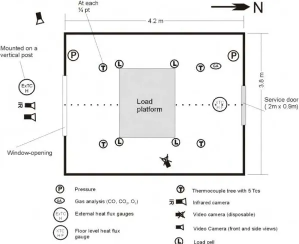
3.1 Instrumentation
Figure 5 shows a plan view of the instrumentation in the CFMRD test room. Numerous types of instrumentation were installed in the test room, but only those relating to the results discussed in this report are described. A detailed description of the design of the test room and other types and locations of instrumentation has been published separately [13].
The test room was instrumented with load cells, Gardon heat flux gauges, thermocouples (TCs) and velocity probes in order to take the following measurements: mass loss, total heat flux on gauges installed flush with the internal surfaces (walls and ceiling), temperatures at numerous locations and gas velocities in the window opening. Table 7 gives the coordinates of the heat flux gauges on various surfaces.
Temperature measurements were made using various types of Chromel-Alumel (Type-K) TCs: TC “trees”2, single TCs attached to wall surfaces and single TCs installed in the window opening. For all other installations, two types of exposed TCs were used: bare and fast-response
prefabricated sheathed types. The bare TCs were manufactured in-house by fusion-welding the twisted ends of 24 gauge Chromel-Alumel wires to form the TC bead. Four TC trees were installed at the center of each of the floor area’s quadrants and each TC tree consisted of five TCs
suspended from the ceiling at the following heights above the floor: 0.40 m, 0.90 m, 1.40 m, 1.90 m and 2.38 m. The TC located at the 2.38 m height on the tree was attached to the ceiling.
Measurements of the mass flow rate, gas temperature and concentrations of oxygen, carbon dioxide and carbon monoxide were taken in the vertical section of the hood exhaust duct to
facilitate calculation of the HRR by using the oxygen consumption method [18]. A pulsed white light smoke meter, which has been described by Crampton and Lougheed [19], was installed in the exhaust duct (Figure 4) for measuring smoke density in the diluted stream.
Table 7. Co-ordinates of heat flux gauge installations on the ceiling and walls of the test room.
Ceiling South wall North wall West wall East wall
Location no. 1 (1.05, 2.85, 2.34)1
(0.00, 2.85, 1.8) (4.20, 0.95, 1.8) (3.15, 3.80, 1.8) (1.05, 0.00, 1.8)
Location no. 2 (3.15,0.95,2,34) - - - -
1 X, Y, Z co-ordinates in m (Directions: X – width; Y – length; Z – height; Origin: south-east corner)
3.1.1 Data Acquisition System
A 16-bit Solartron (Schlumberger) Instruments distributed data acquisition system with 3595 series isolated measurement pods (each having 20 channels) and a personal computer interface was used to record all measurements directly to a hard disk drive at specified time intervals. All temperature data were instantly processed by the data acquisition system and recorded as
temperature values with an accuracy of better than 1oC. Outputs from heat flux gauges, load cells, pressure transducers, gas analyzers and the smoke meter were recorded as either direct current (DC) voltage or electric current values (mV or mA) and were converted by applying the appropriate calibration constants during the post-experiment data processing stage. The sensitivity of the data acquisition system for voltage and current measurements is 1 μV and 10 nA, respectively.
3.2 Ignition Sources and Test Procedures
Various types of propane ignition sources were used for the ignition of the different types of
furnishings that were tested. Table 8 lists the ignition sources used and their origins. In the case of mattresses and upholstered chairs, the indicated test standards were selected as the basis for initiating the fire experiment. In that case, the placement of the burners, strength and duration of applying the ignition source was in accordance with the test standard.
Table 8. Ignition sources used in experiments. Type of Test Specimen Ignition source Strength Reference Standard Mattresses Dual T-burners Horizontal: 18 kW (12.9 L/min) for 70s Vertical: 9 kW (50s) 16CFR1633 [9]
Bed assemblies and bed clothes
T-burner 9 kW (6.6 L/min) for 50s
positioned 0.47 m from the head-side
Ad hoc – derived from 16CFR1633 Upholstered chairs and
sofas
Square-burner
19 kW (13.0 L/min) for 80s ASTM 1537 [20]
Secondary combustible furnishings
T-burner 19 kW for 80s or longer Ad hoc
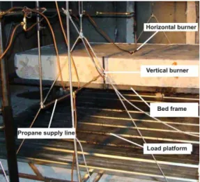
The dual burner ignition source used for testing mattresses was developed by the National Institute of Standards and Technology (NIST) [6] to simulate the heat imposed on a mattress and foundation set by burning bed clothes. Figure 6 shows the arrangement of the ignition system, which consists of two T-shaped burners with different propane flow rates and duration of application, as indicated in Table 8. The ignition system was positioned within 0.30 m of the mid-point of the length of the test specimen. Flames from the vertical burner impinged on the side of the specimen for 50 s at a flow rate of 6.6 L/min (9 kW). Flames from the top (horizontal) burner impinged on the top of the specimen for 70 s at a flow rate of 12.9 L/min (18 kW). Figure 7 shows the flames from the two burners impinging on the specimen at the start of the test. For other items, a single T-burner was used, but the strength and duration of the ignition source was decided on an ad hoc basis
depending on the ease of ignitability of the items being tested. For instance, in the case of bed clothes and bed assemblies, the dual T-burner ignition source was deemed to be unsuitable since it was intended to simulate the heat imposed by burning bed clothes on a mattress. Therefore, a smaller ignition source of 9 kW provided by a vertical T-burner, with flames impinging on the side of the mattress was used instead. The T-burner was positioned at a distance of 0.47 m from the head side end of the bed as shown in Figure 8. The photograph in Figure 9 shows a test specimen being ignited with a square-burner.
Figure 6. Mattress test arrangement
showing the positioning of the dual T-burner system in Test 6.
Figure 7. Ignition of the test specimen using the dual T-burner system.
Figure 8. Ignition of a test specimen in Test 21 using a T-burner.
Figure 9. Ignition of a test specimen in Test 36 using a square-burner.
3.2.1 Test Procedures
The data acquisition (including video cameras) was started at least 60 s before ignition in order to collect pre-ignition data. A data acquisition rate of 2 s was used for all the tests. All the test specimens were placed on the load platform at a distance of 1.50 m from the inside edge of the window opening. The specimens were centered along the width of the room and ignited using the ignition source listed in Table 8. Mattresses were placed on a 0.50-m-high steel bed frame (without a foundation). The foundation for bed assemblies using a posture box was placed on a 0.23-m-high steel bed frame.
The tests were terminated after flaming had ceased or subsided considerably. Termination of the tests was usually carried out by extinguishing the flames or hot embers with water. The debris was collected and weighed after a few days had elapsed to allow the water to evaporate. This provided an estimate of the mass of material that was consumed during the fire, in addition to measurements from the load cells.
It is acknowledged that the ignition sources listed in Table 8 are severe in comparison to realistic igniters such as matches, cigarette lighters and candles, which are often mentioned in many fire statistics as the major causes of residential fires. However, it is common practice in the fire research community to use ignition sources similar to those listed in Table 8 for the benefit of standardization and repeatability. Weaker ignition sources may affect the time to ignition; however, it is believed that the post-ignition phase, during which the fire becomes self-sustaining, is the most important period in studying fire behavior and hence the reason for selecting stronger ignition sources that ensure ignition. A study on the influence of ignition sources on HRR in a furniture calorimeter [21] compared propane burners with ignition strengths ranging from 1.7 kW to 30 kW and found that the burning behavior of the burning items was similar regardless of the type of burner used. As well, the repeatability was better when a stronger ignition source was used. In that study they considered a HRR of 50 kW to be the fire size that can be detected by persons who are not fully alert or those who are further away from the burning item or a fire detector. Therefore, the period before sustained ignition occurs is considered to be relatively unimportant to the assessment of burning behavior and can be accounted for by appropriately modifying the time to ignition or attainment of the experimental HRR at ignition. The above methods have also been supported by Babrauskas and Peacock [22] who stated that although fire deaths were mainly caused by the inhalation of toxic gases, HRR was still the best indicator of fire hazard and that the relative toxicity of combustion gases, and delays in the ignition time as measured by small flame tests, had been shown to have a minor effect on the development of the fire hazard.
3.3 Data Processing
3.3.1 Heat Release Rate
The heat release rate (HRR) was calculated using the well-established method of oxygen-consumption calorimetry. The equations used were those derived by Janssens [18] and cited in numerous standard test methods from organizations such as the American Society for Testing and Materials (ASTM), National Fire Protection Association (NFPA) and the International Organization for Standardization (ISO). Measurements of O2, CO2 and CO were used to calculate the HRR, and
approximation alone results in an uncertainty of 5% in the calculated HRR. Uncertainties in the measurement of other variables such as O2 and mass flow are known to increase the uncertainty by
as much as 5% [23]. During the calibration of the calorimeter [13], using a propane burner, it was found that the accuracy of HRR measurement was within 10% for HRRs greater than 1,000 kW. For such a large calorimeter, the system noise (and uncertainty) is expected to be greater during periods of low HRR due to low O2 depletion as discussed by Brohez [24]; therefore, the HRR data
presented in this report were not smoothed. The use of smoothing techniques, such as running time averages was considered, but was not pursued since there is a possibility of damping out some real features. The subject has also been discussed by Byrant and Ohlemiller [23] in the design of a 3 MW HRR calorimeter. They reported that a “20 s smoothing reduced the apparent peak values by a couple of percent”. Figure 10 shows what happens when “noisy” low HRR data from an experiment conducted during this study was smoothed using a running average method; the result was a 35% attenuation of the unsmoothed peak HRR. Figure 11 confirms that the noise in the HRR data was from the O2 measurements, since a large calorimeter was used. A smaller
calorimeter would have improved measurement accuracy in such a case; however it was not practical to use two calorimeters during the study.
Figure 10. Effect of smoothing “noisy” HRR data.
Figure 11. Fluctuations in O2 measurements at
low oxygen depletion.
3.3.2 Optical Density
The optical density per meter (OD/m) was processed using in-house calibration data. The total smoke released (TSR) was calculated using the procedure outlined in an ASTM test standard [20] .
Time (s) 0 120 240 360 480 600 720 840 960 10801200132014401560 Heat Re lease Rat e (kW ) 0 100 200 300 400 Unsmoothed data Smoothed data Time (s) 0 240 480 720 960 1200 1440 1680 O2 Co ncentr atio n in Exhau st Flow ( % V o l) 20.65 20.70 20.75 20.80 20.85 20.90 20.95
4 RESULTS AND DISCUSSION: PRIMARY COMBUSTIBLE
FURNISHINGS
All of the results are given in a Table in Appendix C.
4.1 Selection of a Mattress
The results of five tests that were conducted to select a suitable mattress are summarized in Table 9. Table 10 gives the ranking of the experimental results. All the mattresses ignited readily and resulted in self-propagating fires by the time both ignition burners were turned off. A detailed discussion of these results has been provided in a separate publication [25]
Table 9. Summary of experimental results for the mattress-selection tests.
Test ID HRRmax THR ODMmax HC
mf
Q
′′
Q
mwc′′
T
∞ (kW) (MJ) (OD/m) (MJ/kg) (oC) (kW/m2) (kW/m2) (oC) 5-SI-03 1,808 (174)1 144 (5.4)2 0.4 26.7 594 (101)3 [722 SE]4 10 39 (20)3 [67 SW CS]4 18 6-SI-01 3,790 (234) 257 (12.5) 1.3 20.6 835 (54) [899 SE] 42 98 (32) [138 W wall] 18 7-SI-02 2,238 (258) 250 (9.3) 0.6 26.9 728 (135) [860 SE] 13 55 (27) [92 SW CS] 18 8-SI-04 3,757 (278) 328 (13.3) 1.7 24.6 924 (40) [978 NW] 87 111 (28) [160 W wall] 18 14-SI-06 3,796 (233) 282 (10.5) 2.4 26.9 905 (41) [956 SW] 46 100 (33) [129 N wall] 20Tmax – Maximum temperature; – Maximum average room temperature (of four TC trees); Qmf′′ – Maximum heat flux at floor level;
mwc
Q′′ – Maximum average heat flux on the walls and ceiling; THR – Total heat released; SW C: SW ceiling location; W wall: West wall; N wall – North wall; NE C – NE ceiling location
1
Time to reach the peak HRR (s); 2
Mass loss (kg); 3
Standard deviation (SD); 4
max
T or Qmax′′ and its location.
Table 10. Ranking of experimental results for the mattress-selection tests.
Test ID Peak HRR (kW) Peak time (s) THR (MJ) Peak (OD/m) (oC) " (kW/m2) " (kW/m2) Total Score 5-SI-03 5 1 5 5 5 5 5 31 6-SI-01 2 3 4 3 3 3 3 21 7-SI-02 4 4 3 5 4 5 4 29 8-SI-04 3 5 1 2 1 1 1 14 14-SI-06 1 2 2 1 2 2 2 12
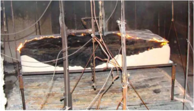
Figures 12 and 13 show the typical features of flaming out of the window opening: a) limited or no flaming; or b) extensive flaming out of the window opening (also indicative of flashover fires), respectively.
Figure 12. Typical fire with mattresses SI-02 or SI-03 (limited flaming out of the window opening).
Figure 13. Typical fire with mattresses 01, SI-04 or SI-06 (extensive flaming out of the window opening with copious dense smoke).
Figure 14. HRR vs. time for mattresses. Figure 15. Average maximum room
temperature at ceiling height (2.38 m) vs. time graphs for mattresses.
Figure 14 shows the graphs of HRR versus time for all five mattresses and Figure 15 shows the average temperature profiles measured at a height of 2.38 m on all four thermocouple trees in the room. All the mattresses have Gaussian-like HRR profiles, due to the accelerated rate of fire growth towards the peak HRR followed by a rapid decrease in the HRR, as there were no components present, such as wood, that have a slower burning rate. Analysis of the results shows that the HRR began to decline after 45% to 70% of the mass of the specimen had been consumed.
Time (s) 0 60 120 180 240 300 360 420 480 540 600 Heat R el ease R ate (kW ) 0 500 1000 1500 2000 2500 3000 3500 4000 6-SI-01 7-SI-02 5-SI-03 8-SI-04 14-SI-06 Time (s) 0 60 120 180 240 300 360 420 480 540 600 A ve rage T empe rat ur e ( o C) 0 100 200 300 400 500 600 700 800 900 1000 6-SI-01 7-SI-02 5-SI-03 8-SI-04 14-SI-06
Mattress SI-03 (Test 5) had the lowest peak HRR due to its low combustible mass (5.3 kg) although it had the fastest fire growth rate. This was likely the result of the flames spreading into the inner core at a faster rate as the fire quickly consumed the thin layer of padding material on the sides compared with the other innerspring mattresses. Mattress SI-06 (Test 14) had the highest peak HRR, albeit only marginally greater than that of second-ranked mattress SI-01. Overall, innerspring mattresses (SI-02, SI-03 and SI-06) exhibited faster fire growth rates compared with the solid core mattresses (SI-01 and SI-04). The fire growth rate of SI-04 was slower partly due to the cotton-based ticking material, which likely formed a protective layer of char. As well, the higher density of the visco-elastic used in mattress SI-04 may have contributed to the slower rate of fire growth. By comparison, SI-01 was not a truly solid core construction since there were air pockets in the mattress created by the convoluted egg-crate structure of the two outer PUF layers (Figure B-4; in Appendix B). This may have contributed to its faster rate of fire growth compared with SI-04. In all the experiments, the HRR profiles show an accelerated rate of fire growth beyond a HRR value of approximately 500 kW, which is likely due to room effects (radiation feedback from the walls and hot layer). For all innerspring mattresses, the ticking and padding material near the ignition zone burnt away quickly (Figure 16) exposing the inner cores of the mattresses and possibly contributing to the faster fire growth rates they exhibited compared to solid core PUF mattresses. The peak HRRs of mattresses SI-01, SI-04 and SI-06 are all comparatively high values of around 3,700 kW. This was an interesting result for SI-06 given that other innerspring mattresses had lower peak HRRs. However, a look at the combustible mass fraction of SI-06 given in Table 2 reveals that SI-06, which was constructed with the lighter independently wrapped (pocket) coils rather than with open coil spring units, had a higher percentage of combustible material. Open coil spring units have a greater weight than independent (pocket) coils since they tend to be
constructed out of heavier gauge wire. Therefore, the higher mass fraction of PUF in a foam-encased independent coil mattress is one of the reasons for the higher HRR produced by SI-06. Another reason is that the excessive melting behavior exhibited by the PUF in SI-06 (Figure 17) contributed to its higher peak HRR due to the additional burning area of the resulting pool fire, coupled with earlier ignition of the underside of the mattress by the pool fire. Other researchers [26] have observed that the type and style of design of a mattress and specific combination of
components used could be major factors in fire performance. In experiments with mattresses constructed with fire-retarded PUF, it was found that some innerspring mattresses had poorer performance than solid core mattresses using the same type of PUF [26]. This seems to suggest that the presence of voids in a mattress core due to spring units or convoluted PUF structures may
accelerate fire growth. However, the experiments conducted in this work were insufficient to draw firm conclusions about the effect of the internal structure of a mattress on its burning behavior.
Figure 16. Typical fire development with innerspring mattress.
Figure 17. Dripping of melted PUF and formation of a pool fire during the test with mattress SI-06.
The average temperature profiles given in Figure 15 show that mattress SI-06 had the highest and fastest-occurring average peak temperature, followed by SI-04. Since temperature rise in a fire compartment is driven by HRR, it is not surprising that the peak temperature in the test with SI-04 occurred at a later time, in agreement with the occurrence of the peak HRR.
Figure 18. South-side average temperature profiles at various heights for Test 14-SI-06.
Figure 19. North-side average temperature profiles at various heights for Test 14-SI-06. Figures 18 and 19 show the stratification of temperatures (average of two TC trees) in the south and north sections, respectively, of the fire room for Test 14-SI-06. The temperatures at the lowest point (0.4 m height) were typically higher in the north side of the test room compared to the south side, which experienced a cooling effect due to the inflow of fresh air from the window opening. Both temperature profiles are similar and the peak temperature values are identical since the test
Time (s) 0 60 120 180 240 300 360 420 480 540 600 Temp erat u re (º C) 0 200 400 600 800 1000 2.4 m 1.9 m 1.4 m 0.9 m 0.4 m Time (s) 0 60 120 180 240 300 360 420 480 540 600 Tempe rat ure (º C) 0 200 400 600 800 1000 2.4 m 1.9 m 1.4 m 0.9 m 0.4 m
specimens were symmetrically positioned in the room. In some experiments, a faster rate of temperature decline was recorded in north side of the room likely due to reduced oxygen conditions, which results in a lowering of the HRR and hence temperatures.
4.1.1 Conclusion
Three of the test specimens (SI-01, SI-04 and SI-06) gave rise to flashover fires, based on widely accepted criteria, i.e. exceeding thresholds of 600 oC in the hot layer and an incident heat flux of
20 kW/m2 at floor level [15]. Specimen SI-06 clearly caused the most severe fire in terms of the magnitude of the peak HRR and the speed with which it occurred. Although it had the slowest rate of fire growth, the fire involving specimen SI-04 attained a comparatively high peak HRR and the highest levels of total heat flux that were measured. On account of these results, specimens SI-04 and SI-06 were selected for subsequent tests with bed assemblies in order to gauge the fire behavior of both innerspring and solid core mattresses. As well, the increasing presence of visco-elastic PUF in sleep products in the marketplace, as it is touted to offer comfort levels that are somewhat superior to ordinary PUF, made SI-04 an interesting specimen for further experiments. SI-01 was not considered for further tests since its fire behavior (rate of fire growth and peak HRR) was similar to that of SI-06.
It is also recognized that although SI-02 was not considered for further experiments on account of its lower peak HRR, it may represent a more severe scenario in smaller sized rooms where it could cause flashover to occur sooner than the other specimens would, given its faster rate of fire growth.
4.2 Additional Tests with Mattresses
The results of two additional tests (not part of the selection process) that were conducted with mattresses are given in Table 11. Specimen SI-05 was an open-flame-resistant mattress design, which had a certificate of conformation to the 16CFR1633 test standard. The experiment was conducted in accordance with the test standard and specimen SI-05 was found to be in conformance with the standard based on the peak HRR criteria - The HRR did not exceed 200 kW (Figure 20) and the experiment was terminated after 30 min. However, it was impossible to determine whether the 15 MJ criterion was met due to the excessive noise in the HRR profile. Figure 21 shows the condition of the test specimen at the end of the experiment; the fire did not breach the barrier fabric and a large portion of the ticking remained unaffected.
Test 35 was conducted to check the repeatability by comparison with Test 8 (identical SI 04 mattresses). The graphs of HRR and room temperature vs. time are given in Figures 22 and 23, respectively. The slower progression of the fire during Test 35 (and consequently lower peak HRR) was attributed to the lower ambient temperatures since the test was conducted during a cold winter
day, which likely had an adverse effect on the intensity of thermal feedback during the pre-flashover period given the large difference in ambient conditions. Review of the test videos (Figures 24 and 25) shows evidence of slower surface flame spread during Test 35.
Table 11. Summary of Experimental Results for Mattresses.
Test ID HRRmax THR ODMmax HC
mf
Q
′′
Q
mwc′′
T
∞ (kW) (MJ) (OD/m) (MJ/kg) (oC) (kW/m2) (kW/m2) (oC) 28-SI-05 < 200 (67)1 N/A (3.0)2 0.05 N/A 41 (4) 3 [47 SW]4 N/A 0.8 (0.2)3 [0.9 NE C]4 18 35-SI-04 3,351 (336) 265 (13.1) 1.9 20.2 749 (151) [921 SE] 29 66 (32) [129 SW CS] -24 1Time to reach the peak HRR (s); 2 Mass loss (kg); 3 Standard deviation (SD); 4 Maximum room temperature / heat flux (oC / kW/m2) and its location.
Figure 20. HRR vs. time for Test 28-SI-05. Figure 21. Condition of specimen SI-05 at the end of the experiment.
Figure 22. HRR vs. time for mattress SI-04 in Tests 8 and 35.
Figure 23. Average maximum room temperature vs. time for mattress SI-04 in Tests 8 and 35. Time (s) 0 360 720 1080 1440 1800 2160 2520 H eat Rele ase R a te ( k W ) 0 100 200 300 400 500 Time (s) 0 60 120 180 240 300 360 420 480 540 600 He at Re lea s e R ate ( k W ) 0 500 1000 1500 2000 2500 3000 3500 4000 8-SI-04 35-SI-04 Time (s) 0 60 120 180 240 300 360 420 480 540 600 A ve rag e T emp era tu re ( oC) 0 100 200 300 400 500 600 700 800 900 1000 8-SI-04 35-SI-04
Figure 24. Fire progression at 210s in Test 8-SI-04.
Figure 25. Fire progression at 210s in Test 35-SI-04.
4.3 Selection of Bed clothes
Table 12 shows the results of experiments with various combinations of bed clothes that were listed in Table 3. It was found that Setup #1, with the comforter not folded back, resulted in a faster rate of surface flame spread since the pillows were ignited earlier and the radiation from the resulting plume helped to accelerate the rate of flame spread. Figures 26 and 27 show the progression of the fire in Tests 11-SI-08 and 19-SI-83, respectively. In reality, Setup #1 (with an actual bed assembly) would likely promote a faster rate of fire growth than Setup #2. This conclusion is based on the times it took for the flames to reach the pillow (head side) and the foot of the bed, which are indicated in Table 12. Test 12-SI-07 had a considerably higher peak HRR since a PUF mattress pad (topper) was included in the assembly. This layout was of interest since mattress pads of various thicknesses and types of PUF are widely available on the market place.
Table 12. Summary of experimental results for the bed clothes-selection tests.
Test ID HRRmax Time to peak Total
mass (kg) (oC) Setup pillow
t
t
foot (kW) (s) (s) (s) 11-SI-08 268 466 6.7 126 #2 (folded) 260 240 12-SI-07 388 582 7.8 204 #2 170 230 17-SI-75 210 756 4.6 143 #2 390 78019-SI-83 N/A1 N/A 5.2 156 #1 (not folded) 60 98
30-SI-83 197 378 5.2 112 #1 N/A 120
pillow
t
: Time reach the pillow; - foott
: time to reach the foot of the bed.1
Figure 26. Flame spread in Test 11-SI-08. Figure 27. Flame spread in Test 19-SI-83..
4.3.1 Conclusion
Setup #1 and the combination of bed clothes used in Test 19-SI-83 was selected to be the standard arrangement for experiments with bed assemblies on account of the faster rate of surface flame spread. The peak HRR was not used as a selection criteria since the bed clothes were to be tested with non-flame resistant mattresses, which would be the dominant source of fuel. The measured peak HRRs were comparable with values published by other researchers: California Bureau of Home Furnishings (125 – 167 kW ) [5] and NIST (up to 200 kW) [27].
4.4 Bed Assemblies
4.4.1 Bed Assemblies Using Twin-Size Solid Core and Innerspring Mattresses
The results of tests with twin-size bed assemblies using solid core and innerspring mattresses SI-04 and SI-06 (complete with foundation and bed clothes) are summarized inTable 13. The results from Table 9 of the mattress-only tests using similar mattresses are repeated here (shaded rows) for ease of comparison.Table 13. Summary of Experimental Results for Bed Assemblies.
Test ID HRRmax THR ODMmax HC
mf
Q
′′
Q
mwc′′
T
∞ (kW) (MJ) (OD/m) (MJ/kg) (oC) (kW/m2) (kW/m2) (oC) 8-SI-04 3,757 (278)1 328 (13.3)2 1.7 24.6 924 (40)3 [978 NW]4 87 111 (28)3 [160 W wall]4 18 21-SI-10 2,978 (394)1 773 (35.8)2 0.9 21.5 826 (87)3 [933 SE]4 25 77 (28)3 [99 W wall]4 29 14-SI-06 3,796 (233) 282 (10.5) 2.4 26.9 905 (41) [956 SW] 46 100 (33) [129 N wall] 20 23-SI-76 3,358 (332) 595 (32.5) 1.3 18.3 891 (41) [942 SW] 20 95 (37) [140 W wall] 18 1Time to reach the peak HRR (s); 2
Mass loss (kg); 3
Standard deviation (SD); 4
max
T
orQ
max′′
and its location.Figure 28. HRR vs. time for twin-size bed assemblies and two different mattresses.
Figure 29. Average maximum room temperature vs. time profiles at 1.9 m height for twin-size bed assemblies and two different mattresses.
The graphs of HRR and room temperature are given in Figures 28 and 29, respectively. The results show that the HRRs and HC values of the mattresses alone were higher and occurred earlier than those obtained with the bed assemblies. The room temperatures and, consequently, the total heat flux recorded by the gauges were lower for the bed assembly tests, which is consistent with the lower HRRs.
There was a considerable reduction in the peak HRR in Test 21 (using mattress SI-04) compared with Test 8 (mattress only). For all the tests, the initial rate of fire growth was comparable until after about 180s into the tests. It is interesting to note that the peak optical density per meter (OD/m) was significantly lower in the bed assembly tests. The total heat released (MJ) for the bed
Time (s) 0 120 240 360 480 600 720 840 960 1080 1200 Heat Release Rat e (kW) 0 500 1000 1500 2000 2500 3000 3500 4000
21-SI-10 (Bed with SI-04) 23-SI-76 (Bed with SI-06) 8-SI-04 (Mattress only) 14-SI-06 (Mattress only)
Time (s) 0 120 240 360 480 600 720 840 960 1080 1200 T e m per at ure ( o C) 0 200 400 600 800 1000 21-SI-10 23-SI-76 8-SI-04 14-SI-06
assembly tests is considerably greater than for the mattress-only test due to the contribution from the posture box, as can be expected.
The extent of flaming out of the window opening was observed to be more intense during the mattress-only tests (e.g. Test 14-SI-06; Figure 30) than it was during the tests with twin-size bed assemblies (e.g. Test 23-SI-76; Figure 31). The behavior of the fire around the time of flashover was more vigorous during the mattress-only tests than in the bed assembly tests (Figures 30 and 31, respectively).
Figure 30. Test 14-SI-06 – Extent of flaming out
of the window opening. Figure 31. of the window opening.Test 23-SI-76 – Extent of flaming out
Figure 32. Test 8-SI-04 (mattress only)– Features of the fire during the period leading to flashover.
Figure 33. Test 21-SI-10 (bed assembly using
mattress SI-04) – Features of the fire during the period leading to flashover.
As noted earlier (Section 6.1.1), excessive melting and dripping of PUF was observed in the mattress-only tests. It is believed that this contributed to the higher peak HRRs obtained with a mattress alone due to the additional burning area of the resulting pool fire coupled with earlier
ignition of the underside of the mattress by the pool fire. Figures32 and 33 show the differences in the features of the fires during Test 8 (mattress only) and Test 21 (bed assembly), respectively. There was visibly less dripping during Tests 21 and 23.
Bed clothes and the presence of a foundation likely contributed to the outcome of Tests 21 and 23. However, a fair comparison between the burning behavior of the bed assemblies and mattresses alone cannot be made due to the differences in the ignition methods: mattresses were ignited with a significantly stronger flame (9 kW side burner plus 19 kW top burner) positioned near the center of the front side (Figure 7), whereas the bed assemblies were ignited with a smaller 9 kW flame placed at 0.47 m from the head side (Figure 8). Despite these differences, it is interesting to contemplate the potential effect of bed clothes. Indeed, other researchers have investigated this issue, albeit in the context of the effect of bed clothes on open-flame resistant mattresses [27], and found that bed clothes had an effect on the burning behavior of bed assemblies.
It is likely that the slower rate of fire growth in Tests 21 and 23 is due to the combined effect of the protection that the bed clothes provided to the mattresses and the longer path the flames had to travel to cover the top surface since the ignition source was located near one end of the bed assembly. The fact that the bed assemblies had lower peak HRRs than their corresponding mattresses is possibly due to the slower rate of fire growth and differences in melt-pool formations – there is a discernible trend that for items with comparable combustible mass, a slower fire growth rate reduces the peak HRR.
4.4.1.1 Concluding Remarks
The results re-affirmed the choice of mattress SI-06 for use in the bed assemblies in future tests. It is recognized that a mattress alone placed on a supporting frame without bed clothes (a rare occurrence in an occupied room) could result in a more severe fire initiation than would be the case with a bed assembly. Nevertheless, the use of a bed assembly as the first ignited item is consistent with the project’s objective of simulating realistic fuel load configurations.
4.4.2 Effect of Bed Assembly Size and Other Parameters
Table 14 summarizes the results of experiments with various sizes of bed assemblies, including a bunk bed. The bunk bed (stacked bed; Figure B-33; in Appendix B) that was tested was of the so called “twin-over-double” configuration, i.e. the lower section was a double bed assembly and the upper section was a twin bed assembly, without posture boxes.
Table 14. Summary of Experimental Results for Bed Assemblies.
Test ID HRRmax THR ODMmax HC
mf
Q
′′
Q
mwc′′
T
∞ (kW) (MJ) (OD/m) (MJ/kg) (oC) (kW/m2) (kW/m2) (oC) 23-SI-76 3,358 (332)1 595 (32.5)2 1.3 18.3 891 (41)3 [942 SW]4 20 95 (37)3 [140 W wall]4 18 29-SI-12 3,971 (247) 809 (40.7) 2.6 20.6 1,026 (21) [1,057 NE] N/A 173 (32) [223 S Wall] 18 31-SI-13 3,762 (466) 835 (47.9) 2.7 18.2 1,052 (16) [1,071 NE] 128 177 (26) [221 S Wall] 20 32-SI-14 6,258 (248) 957 (38.7) 2.4 21.4 1,003 (39) [1,061 NE] 89 167 (36) [221 E CS] 24 1Time to reach the peak HRR (s); 2
Mass loss (kg); 3
Standard deviation (SD); 4
Maximum room temperature / heat flux (o
C / kW/m2
) and its location.
The HRR and room temperature profiles are shown in Figures 34 and 35, respectively. There was a considerably greater increase in all the measured results moving from the twin size bed assembly (Test 23) to the double bed assembly (Test 29). As well, there was greater flame extension and luminosity of the flames issuing out of the window opening in Test 29 (Figure 36) compared with Test 23 (Figure 31). Comparing the peak HRRs, Test 23 was well below the theoretical ventilation limit of ~4,100 kW, whereas Test 29 approached the limit and hence the increase in flame
extension and brightness. However, the most striking result is the extent by which the thermal radiation measured by the heat flux gauges increased. Whereas, the peak temperature rose by a modest 12%, the radiation intensity, being proportional to the fourth power of absolute temperature, increased by about 60% indicating a considerably greater increase in the potential thermal assault on the room boundaries in Test 29. However, it must borne in mind that the heat flux gauges measure the total heat flux (including the convective portion), therefore the actual incident radiation heat flux on wall surfaces is expected to be lower since it is a result of the net radiation exchange between the wall surface (which is at higher temperature than the cooled gauge) and the
neighbouring fire environment. Surface temperatures were recorded during the experiments and will be analyzed further in separate publications to estimate the energy balances, i.e. wall losses versus convective and radiation losses through the window.
Figure 34. HRR vs. time for various sizes of bed assemblies.
Figure 35. Average maximum room temperature vs. time graphs for bed assemblies.
Figure 36. Test 29-SI-12 – Post-flashover fire with external flaming.
Figure 37. Test 32-SI-14 – Post-flashover fire with extensive external flaming.
In moving from a double (Test 29) to a queen (Test 31) bed assembly, there was a slight decrease in peak HRR, but the temperature and heat flux results were comparable. Test 31 had a slightly higher peak temperature than Test 29 due to the great total heat released The rate of fire growth in Test 31 was slower because a different set of bed clothes was used, i.e. the material composition of the components was similar but the comforters had different fabric prints. The slower rate of fire growth (and mass is consumed progressively) is one of the factors that likely contributed to the reduction of the peak HRR compared with Test 29. There is a greater proportion of the mass
Time (s) 0 180 360 540 720 900 1080 Heat Re le ase Ra te ( k W ) 0 1000 2000 3000 4000 5000 6000 23-SI-76 (Twin) 29-SI-12 (Double) 31-SI-13 (Queen) 32-SI-14 (Bunk) Time (s) 0 180 360 540 720 900 1080 Tempe rat ur e ( o C) 0 200 400 600 800 1000 1200 23-SI-76 (Twin) 29-SI-12 (Double) 31-SI-13 (Queen) 32-SI-14 (Bunk)