Publisher’s version / Version de l'éditeur:
ASM Proceedings of the International Conference: Trends in Welding Research,
pp. 72-80, 2008-06
READ THESE TERMS AND CONDITIONS CAREFULLY BEFORE USING THIS WEBSITE.
https://nrc-publications.canada.ca/eng/copyright
Vous avez des questions? Nous pouvons vous aider. Pour communiquer directement avec un auteur, consultez la
première page de la revue dans laquelle son article a été publié afin de trouver ses coordonnées. Si vous n’arrivez pas à les repérer, communiquez avec nous à PublicationsArchive-ArchivesPublications@nrc-cnrc.gc.ca.
Questions? Contact the NRC Publications Archive team at
PublicationsArchive-ArchivesPublications@nrc-cnrc.gc.ca. If you wish to email the authors directly, please see the first page of the publication for their contact information.
NRC Publications Archive
Archives des publications du CNRC
This publication could be one of several versions: author’s original, accepted manuscript or the publisher’s version. / La version de cette publication peut être l’une des suivantes : la version prépublication de l’auteur, la version acceptée du manuscrit ou la version de l’éditeur.
Access and use of this website and the material on it are subject to the Terms and Conditions set forth at
Effect of welding speed on lap joint quality of friction stir welded AZ31
magnesium alloy
Cao, X.; Jahazi, M.
https://publications-cnrc.canada.ca/fra/droits
L’accès à ce site Web et l’utilisation de son contenu sont assujettis aux conditions présentées dans le site LISEZ CES CONDITIONS ATTENTIVEMENT AVANT D’UTILISER CE SITE WEB.
NRC Publications Record / Notice d'Archives des publications de CNRC:
https://nrc-publications.canada.ca/eng/view/object/?id=3de36bed-170d-4a0f-96ef-707983682810 https://publications-cnrc.canada.ca/fra/voir/objet/?id=3de36bed-170d-4a0f-96ef-707983682810Effect of Welding Speed on Lap Joint Quality of Friction Stir Welded AZ31
Magnesium Alloy
X. Cao, M. Jahazi
Aerospace Manufacturing Technology Center, Institute for Aerospace Research, National Research Council Canada, 5145 Decelles Avenue, Montreal, Quebec, H3T 2B2, Canada
Abstract
Friction stir welding (FSW) is an attractive option to join magnesium alloys, one of the lightest metals for structural applications. In this work, the effect of welding speed ranging from 5 to 30 mm/s on lap joint quality of 2-mm thick AZ31B-H24 magnesium alloy was investigated in terms of weld defects, microstructure, hardness and tensile shear properties. The influence of welding speed on welding defects such as hooking and kissing bond is discussed in detail. Also, the evolution of the microstructure, hardness and tensile shear load as a function of welding speed are studied. The welding process of the lap joints for 2-mm thick AZ31 magnesium alloy was optimized based on the minimization of the hooking defect and the maximization of the tensile shear strength. Sound lap joints with good surface quality, low distortion, lack of cavity and crack defects, with minor hooking and kissing bond, and with high tensile shear strength were successfully obtained indicating the great potential of FSW technique for magnesium alloys.
Introduction
As one of the lightest metallic materials for structural applications, magnesium alloys are increasingly used in various industries, in particular automotive. Weight reduction in transportation industry is one of the most crucial measures to increase fuel economy and reduce pollution. To further expand the application of magnesium alloys, more effective welding and joining techniques are required. Conventionally tungsten inert gas (TIG) and metal inert gas (MIG) processes are the main welding methods for magnesium castings (1). With the introduction of friction stir welding (FSW) technique in 1991, this relatively new solid-state joining process may provide significant potential for magnesium alloy welding since it can reduce or eliminate some solidification-related welding defects such as cracks, porosity, evaporative loss, etc. To date, however, most of the research and development work has concentrated on FSW of aluminum alloys. For example,
FSW of lap joints, a widely used joint type in automotive industry, was reported for some aluminum alloys (2-6) but not for magnesium alloys. Therefore, comprehensive investigations into lap-type FSW of magnesium alloys would allow developing the technological bases for the manufacturing of magnesium alloy components and structures. This investigation is targeted at automotive industry applications and thus high productivity is required. To this end, a tool rotational rate of 2000 rpm was employed to join 2-mm thick magnesium alloy sheets. The effect of welding speed ranging from 5 to 30 mm/s on the lap-joint quality is studied in terms of weld defects, microstructure, hardness and tensile shear properties.
Experimental
method
The experimental alloy is AZ31B-H24 magnesium alloy sheets with dimensions of approximately 1200 × 500 × 2 mm. The alloy has a nominal composition of Al 2.5-3.5 wt. %, Zn 0.7-1.3 wt. %, Mn 0.2-1.0 wt. % and the balance Mg. 300 × 100 × 2 mm specimens were cut from the as-received sheets with the end surfaces machined along the specimen length. The joining regions of the work-pieces were carefully cleaned before the specimens were arranged in lap mode with an overlap width of approximately 28 mm. For all welds the retreating side (RS) of the pin was always located near the top sheet edge (RNE). The welding tool had a scrolled shoulder with a diameter of 19.05 mm and a ¼-20 left hand threaded adjustable pin made of H13 steel with a diameter of 6.35 mm, a thread spacing of 1.27 mm and a pitch of 0.8 thread/mm. The length of the threaded pin was 4.45 mm. The welding direction was perpendicular to the roll direction of the work-piece. The lap joints were welded at a tool rotational rate of 2000 rpm clockwise, the maximum available for the ISTIR MTS FSW machine used in this work. The tilting angle of the pin tool is 0.5º for all the experiments. The welding speed was ranged from 5 to 30 mm/s. The penetration depth was controlled through shoulder plunge depth of approximately 0.25 mm and a pin length of approximately 2.75 mm.
Trends in Welding Research, Proceedings of the 8th International Conference
Stan A. David, Tarasankar DebRoy, John N. DuPont, Toshihiko Koseki, Herschel B. Smartt, editors, p 72-80 DOI: 10.1361/cp2008twr072
Copyright © 2009 ASM International® All rights reserved. www.asminternational.org
The first 50 mm at the beginning and the last 20 mm of each joint were removed to exclude possible unstable welding conditions. Two or three metallurgical specimens were then cut from each joint. These specimens were mounted using cold-setting resin, ground and polished to produce a mirror-like finish. All the specimens were etched in acetic picral [10 mL acetic acid (99%), 4.2 g picric acid, 10 mL H2O, 70 mL ethanol (95%)] for about 6 seconds to reveal grain structures. The macrostructure and microstructure were examined using an Olympus Inverted System Metallurgical Microscope GX71 equipped with Olympus digital camera and AnalySIS Five digital image software. The grain size was obtained according to ASTM standard E112 using the linear intercept method. Vickers microindentation hardness was measured at the mid-thicknesses of the top and bottom sheets using Struers Duramin A-300 hardness tester at a load of 100 g force, a dwell period of 15 seconds and an interval of 0.3 mm.
For each weld joint, three tensile shear specimens were water-jet cut, to give specimen width of 25.4 mm (1 inch) and an overall length of approximately 172 mm as per ASTM D3164. To balance the offset axes of the lap members and minimize the bending effects, two packing pieces as shown in Figure 1 were used during tensile shear testing which was carried out at room temperature using a 50 kN Instron mechanical testing machine. The crosshead speed was fixed at 2 mm/min with a sampling rate of 50 readings per second. For each test the failure loads and locations were recorded.
Figure 1: Tensile stress distribution in an ideal tension-shear specimen.
Results and discussion
Defects
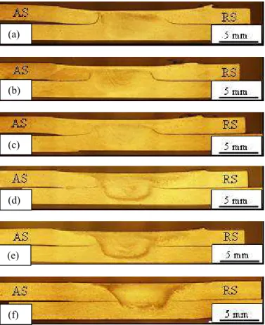
Figure 2 shows the transverse sections of all the welds. The most common defects observed in the FSWed lap joints are hooking and kissing bond. Figure 3 shows high magnification optical micrographs of the hooking defects on both the advancing (AS) and retreating (RS) sides obtained at welding speeds ranging from 5 to 30 mm/s. As shown in Figure 3, the welding speed has significant influences on the formation of hooking defects. Hooking defects were observed on both AS and RS of the joints with those on the RS always upward.
Higher hooking sizes on the RS were obtained at lower welding speeds. However, hooking on the AS can be upward or downward. Higher hooking sizes on the AS were also obtained at lower welding speed. At high welding speed (30 mm/s), however, the hooking on the AS were observed to go slightly downward. The hooking has almost similar size on both sides of the joint as shown in Figure 2. In general, the hook size decreases with increasing welding speed. These indicate that the metal in the stir zone (SZ) near either AS or RS has more upward movement at lower welding speed due to the stronger stirring action of the pin. At high welding speed, hooking defects become small or even disappear. Thus “cold” welding is helpful to reduce hooking defects. During friction stir welding, the rotation of the tool results in material flow around the pin. When rotating clockwise for the left-threaded pin as used in this work, it was reported that the metal is moved upward towards the tool shoulder (2). The interfaces between the top and bottom sheets on both AS and RS are pulled up adjacent to the SZ, as a result of material being forced into the top sheet towards the tool shoulder from below (2). Such a behavior was confirmed for welding speeds below 25 mm/s. At a higher welding speed (30 mm/s), however, the results indicate that the material near the TMAZ (thermomechanically-affected zone) interface on the AS can flow downward. In addition, the hooking on the AS can be gently curved or change its direction abruptly. However, the upward hooking on the RS does not show this tendency.
Figure 2: Transverse sections of lap joints obtained at welding speeds (a) 5, (b) 10, (c) 15, (d) 20, (e) 25 and (f) 30 mm/s.
(a) (b) (e) (d) (f) (c) Stress Stress Top Packing Bottom Packing
5 mm/s 10 mm/s 15 mm/s 20 mm/s 25 mm/s 30 mm/s
Figure 3: Hooking defects on the advancing (left) and retreating (right) sides at various welding speeds.
As a defect of adverse interface reorientation, hooking is usually considered to be detrimental to weld joints for several reasons. Hooking is a crack-like un-welded region appearing on both AS and RS of the lap joints. The hooking interface usually consists of surface oxides in magnesium alloys. This defect is located in the TMAZ but could extend to the interface between the TMAZ and the SZ with gaps becoming smaller towards the SZ (Figures 2 and 3). The crack-like hooking extending to the TMAZ/SZ interface causes sharp discontinuities along the interfaces, leading to acute and sharp notches where the stress becomes highly concentrated (2, 3). In addition, the reorientation of the interface extends the hooking into either the top or the bottom sheet, resulting in a net reduction of “effective sheet thickness” (EST) of the material. The EST is defined as the minimum sheet thickness determined by measuring the smallest distance between any un-bonded interface and the top surface of the upper sheet, or the bottom surface of the lower sheet (2, 4). This parameter introduced by Cederqvist and Reynolds (4, 5), can be used to measure how much of the original sheet thickness is left to carry the load after welding and to characterize the shape and amount of the upward or downward translation of the sheet interface. It was found that higher tensile shear load is achieved at larger EST in aluminum alloys since the lower EST can reduce the load bearing thickness of the material (2, 4, 6).
As shown in Figure 4, the crack-like hooking defects can extend from the TMAZ to the SZ. The extended film-like faint dark lines in the SZ are termed kissing bonds. They usually have irregular morphologies, something like zigzag line, lazy S, wavy pattern, etc. The recurrent oscillating traces of the kissing bond as shown in Figure 5b, leading to the formation of oxide bands, are related to the oscillating welding force during FSW (7). However, the width of the kissing bond is much narrower than that of a hooking defect. It was found that kissing bonds tend to be continuous near the edges of the welds and become more broken up and dispersed toward the center of the welds at low welding speed (< 15 mm/s). At high
welding speeds (≥20 mm/s), the kissing bond in the SZ
becomes more continuous.
As shown in Figure 5, kissing bond is also a crack-like defect, initially originating from the surface oxides present on the surface of the work-piece. The surface oxides in magnesium alloys usually consist of a collection of separate magnesia crystals, resembling to coarse sandpaper. This was well observed in the fracture surface of the FSWed joints (8). The coarse and porous surface oxide also contains some moisture and is usually termed as the “dry” side (9). In contrast, the other side of the surface oxide has atom-to-atom contact with solid metal and is usually termed the “wetted” side. During FSW, the dry side will be stirred into the SZ, deformed, or even fragmented. Thus the entrapped dry side will be in contact with either another dry side of the oxide or the fresh metal in the SZ. In all cases, due to the microscopic roughness or the asperities of the oxide with some absorbed air in its dry side, effective metallic bonding can not be well established at
solid state during FSW, leading to the formation of kissing bond defect. Therefore, the kissing bond is a crack defect in nature. If the stirring action is strong enough, more mechanical bonding will be established. If the oxide films are fragmented, the oxides will become particles and dispersed in the SZ, leading to the formation of solid inclusions. The metallic bond in oxide-oxide, or oxide-fresh metal surfaces may not be well obtained but mechanical bonding can be established at the contact interface under the shear stress during FSW. Better bonding can be further reached at lower welding speed, resulting in the transformation of the continuous oxides into dispersed particles.
Similar to hooking defect, kissing bond is also a crack-like defect and thus is often deleterious to mechanical property including fatigue strength (10). Kissing bond also causes a net reduction of “effective sheet thickness” of the material. The fracture failure preferentially initiates along the kissing bond (3). The presence of kissing bonds can also reduce the mechanical strength due to the considerably higher Young’s modulus of oxides and the resulting strain incompatibility with the surrounding matrix (7).
Microstructure and hardness
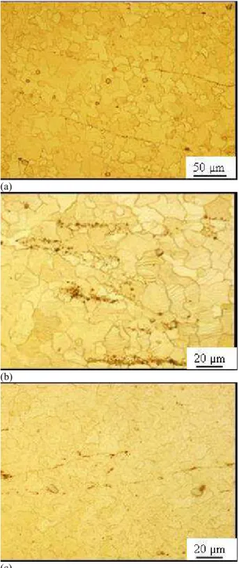
Figure 6 shows typical microstructures obtained in various regions at a welding speed of 25 mm/s. The base metal (BM) has both equiaxed and pancaked grains with various sizes (Figure 6g). The heterogeneity in the grain structure of the base metal may originate from incomplete dynamic recrystalization during the warm rolling. The grains become equiaxed in the SZ and TMAZ, and partially in the HAZ. This is consistent with the microstructure evolution observed in the butt joints of the FSWed AZ31B-H24 alloy (8). The equiaxed grains in the SZ are formed due to the occurrence of dynamic recrystalization during FSW. In the TMAZ the grains are severely deformed, rotated, and elongated due to plastic deformation caused by interaction with the tool, but usually do not recrystallize in aluminum alloys. In the present work, however, the TMAZ was mainly composed of equiaxed grains indicating that recrystalization has already taken place in this zone. As shown in Figure 7, the grains in the SZ become smaller with increasing welding speed. The grains in the SZ are much more uniform and larger than those in the base metal indicating grain coarsening has taken place in the SZ.
It was found that the grains gradually became larger from the BM through the HAZ, to the TMAZ and culminated at the SZ as shown in Figures 6 and 8. The grain coarsening occurring in the SZ and the TMAZ during FSW of AZ31B-H24 alloy is related to the annealing effect induced by welding heat. The sizes of the grains in the SZ and TMAZ depend on the recrystallization and the time available for grain growth, which are ultimately related to processing parameters.
(a)
(b)
(c)
(d)
Figure 4: Extensions of hooking defects on the advancing (a-b) and retreating (c-d) sides obtained at welding speeds 5 and 30 mm/s, respectively.
(a)
(b)
(c)
Figure 5: Kissing bonds in the stir zone obtained at welding Speeds (a) 15, (b) 20 and (c) 30 mm/s.
As a result of continuous grain coarsening from the BM to the SZ, the hardness along the middle-thickness of the joints decreases gradually and the lowest hardness value was reached in the SZ as indicated in Figures 8 and 9. Slight higher hardness is obtained at the bottom sheets (Figure 9). Figure 10 illustrates the effects of welding speed on grain sizes and
hardness in the SZ. The grain size in the SZ decreases with increasing welding speed, resulting in higher hardness values. The SZ hardness is 80 – 90% that of the base metal. The stir zones had lower hardness values compared with the base metal.
Tensile shear properties
As shown in Figure 1, the tensile stress in the top and bottom sheets progressively decreases from the maximum at the loaded end to zero at the unloaded end in an ideal lap shear test (4). The tensile stress contributions of the top and bottom sheets can be superimposed. In each sheet, the side which experiences maximum tensile stress is defined as “loaded” (2). As mentioned above, all welds in this work were configured in such a way that the RS of the pin was always located near the top sheet edge (RNE). Therefore, the loaded side is the AS for the top member (the left side of the SZ in Figure 1), and the RS for the bottom sheet (the right side of the SZ in Figure 1). This corresponds to the A-loaded mode (i.e. AS loaded in the top sheet) by Cederqvist and Reynolds (4), and Ericsson et al (2). In the A-loaded case, the maximum theoretical tensile stress in the top sheet occurs on the AS whereas for the bottom sheet on the RS. Due to stress distribution and the bending stresses possibly present during tensile shear testing, the critical locations will be the AS in the top sheet, or the RS in the bottom sheet for the setup presented in Figure 1.
As shown in Figure 11, the tensile shear strength increases significantly with welding speed up to 15 mm/s and remains constant almost with further increase in welding speed. For all lap joints, it was found that the fracture appears in or near the interface of the SZ/TMAZ on the AS of the top sheets. The AS (left) in the top sheet is the critical location due to the maximum stress present, i.e. fracture was initiated in the highly stressed area and the cracks typically propagated through the weld in the upper sheet. The RS (right) in the bottom sheet has also suffered from maximum stress but no failure appeared in the bottom sheet. This is as if the thickness of the bottom sheet is slightly increased because the hooking on the RS is upward toward the top sheet (Figure 3). Therefore, the AS in the top sheet is expected to be the critical location for fracture failure. In this region, the hooking defects are upward for welding speeds up to 25 mm/s (Figure 3) and their sizes decreased when the welding speed increases from 5 to 30 mm/s. This is as if the thickness of the top sheet increases at higher welding speeds. Clearly, the significant increases observed in tensile shear load could be related to the decreasing hooking size and sharp notch effects of the hooking defects for welding speeds up to 15 mm/s. Above this welding speed, the hooking size has slight variations but much less notch effects are observed when compared with the joints obtained at welding speeds below 15 mm/s. As shown in Figure 3, the hooking defects obtained at welding speeds of 20 – 30 mm/s have their directions changed gradually downward, decreasing the stress concentration for the top sheets. Under these conditions, therefore, relatively high shear loads were obtained.
(a)
(b) (c)
(d) (e)
(f) (g)
(a) (b)
(c) (d)
(e) (f)
Figure 7: Microstructures in the stir zone obtained at welding speeds (a) 5, (b) 15, (c) 20, (d) 25, (e) 30 mm/s, and (f) in the base metal
Specifically, the maximum tensile shear load of 7.38 kN obtained at welding speed of 30 mm/s and tool rotational rate of 2000 rpm displayed only downward hooking defect on the AS. Under these conditions, a tensile stress of approximately 147 MPa [shear load/ (specimen thickness × width)] was obtained with a joint efficiency of approximately 52% in terms of the ultimate tensile strength of the 2-mm AZ31B-H24 base metal.
Figure 8: Distributions of hardness and grain size across the lap joint at the mid-thickness of the top sheet at welding speed of 20 mm/s.
Conclusions
¾ Welding speed has significant influence on the formation of hooking defects. Larger hooking is obtained at lower welding speed.
¾ Tensile shear load increases with increasing welding speed up to 15 mm/s but remains constant with further increase of the speed. The highest shear strength is obtained using a set of welding parameters resulting in downward hooking defect at the maximum stress location of the top sheet.
¾ Dynamic recrystallization was observed in the stir zone and TMAZ and the grain shape became equiaxed. In the HAZ, some partial recrystalization occurred. The grain size in the stir zone decreases with increasing welding speed due to lower heat input.
¾ For a given welding speed, gradual grain growth is observed from the base metal to the stir zone. Correspondingly, the hardness decreases gradually from the base metal through the HAZ, to the TMAZ and then to the stir zone where the lowest hardness is obtained.
(a)
(b)
Figure 9: Typical hardness distributions across the joints at the mid-thickness of the top and bottom sheets at welding speeds (a) 10 and (b) 30 mm/s.
Acknowledgements
This investigation is part of the three-country Canada-China-USA Collaborative Research Project on the Magnesium Front End Research and Development (MFERD). Significant thanks are due to K. Ng, a coop student from McGill for metallurgy. Thanks are also due to Technical Officers, M. Guerin for the preparation of FSWed samples using FSW system and M. Banu for the tensile shear testing and T. Shariff, master student at McGill University, for the measurement of the grain size. Thanks are also due to Magnesium Elektron for the supply of experimental magnesium alloys.
40 60 80 100
-15 -5 5 15
Distance from center (mm)
H V 1 00 g f 0 5 10 15 Gr a in s ize ( µ m )
Hardness Grain size
SZ BM HAZ BM TMAZ HAZ TMAZ AS RS 40 60 80 100 -15 -5 5 15
Distance from center (mm)
H V 100 g f Top Bottom 40 60 80 100 -15 -5 5 15
Distance from center (mm)
H V 100 g f Top Bottom
Figure 10: Effect of welding speed on grain size and hardness in the stir zone.
Figure 11: Effect of welding speed on tensile shear load.
References
[1] Cao, X. et al, “A Review of Laser Welding Techniques for Magnesium Alloys,” J. Mater. Process. Technol., Vol. 171 (2006), pp. 188-204.
[2] Ericsson et al, “Fatigue Properties of Friction Stir Overlap Welds,” Int. J. Fatigue, Vol. 29 (2007), pp. 57-68
[3] Cantin, G.M. et al, “Microstructure Characteristics and Mechanical Properties of Friction Skew-Stir welded Lap Joints in 5083-O aluminum,” Proc. 7th Int. Conf. on Trends in Welding Research, Pine Mountains, GA, USA, May 16-20, 2005, pp185-190.
[4] Cederqvist, L. and Reynolds, A.P., “Factors Affected the Properties of Friction Stir Welded Aluminum Lap Joints,” Welding J. (Res. Supplement), No. 12 (2001), pp. 281-287.
[5] Cederqvist L. and Reynolds A.P., “Properties of Friction Stir Welded Aluminum Lap Joints,” Proc. 2nd Int. Symp. On Friction Stir Welding, Gothenburg, Sweden, 26-28 June 2000. [6] Fersini D. and Pirondi A., “Fatigue Behavior of Al2024-T3 Friction Stir Welded Lap Joints,” Eng. Fracture Mechanics, Vol. 74 (2007), pp. 468-480.
[7] Jene T. et al, “Oxide Fragments in Friction Stir Weld,” 6th Int. Symp. on Friction Stir Welding, Montreal, Canada, 10-12 Oct. 2006, Paper 65, pp. 1-6.
[8] Afrin N. et al, “Microstructure and Tensile Properties of Friction Stir Welded AZ31B-H24 Magnesium Alloy,” Mater. Sci. Eng. A, Vol. 472, (2008), pp. 179-186
[9] Cao X. and Campbell, J., “Oxide Inclusion Defects in Al-Si-Mg Cast Alloys,” Can. Metall. Q., Vol. 44, No. 4 (2005), pp. 435-447.
[10] Sato Y.S. et al, “FIB-assisted TEM Study of an Oxide Array in the Root of a Friction Stir Welded Aluminum Alloy,” Script Mater., Vol. 50 (2004), pp.365-369.
0 5 10 15 5 10 15 20 25 30 Welding Speed (mm/s) G rai ns iz e ( µ m ) 40 50 60 70 80 H V 100 g f Grain Size Hardness HV for base metal
Grain size for base metal
0 2 4 6 8 10 0 10 20 30 40 Welding speed (mm/s) F a ilu re l o a d ( k N ) 80