Automatic 5-axis NC toolpath generation
BY
MAHADEVAN BALASUBRAMANIAM
B. TECH., INDIAN INSTITUTE OF TECHNOLOGY, MADRAS (1997)
S.
M., MASSACHUSETTS INSTITUTE OF TECHNOLOGY (1999)SUBMITTED TO THE DEPARTMENT OF MECHANICAL ENGINEERING
IN PARTIAL FULFILLMENT OF THE REQUIREMENTS FOR THE DEGREE OF
DOCTOR OF PHILOSOPHY IN MECHANICAL ENGINEERING
AT THE
MASSACHUSETTS INSTITUTE OF TECHNOLOGY
MASSACHUSEUTS INSTITUTE OF TECHNOLOGY
,DEC
2001
LIBRARIES
SEPTEMBER 2001
©2001 Massachusetts Institute of Technology All rights reserved
A u th or ...
Department of Mechanical Engineering
June 11, 2001
Certified by ...
/Sanjay E Sarma
Associate Professor of Mechanical Engineering
Thesis Supervisor
A ccepted by ...
Prof. Ain A. Sonin
Chairman, Department Committee on Graduate Students
Automatic 5-axis NC toolpath generation
byMahadevan Balasubramaniam
Submitted to the Department of Mechanical Engineering on June 11, 2001, in partial fulfillment of the Requirements for the Degree of Doctor of Philosophy in
Mechanical Engineering
Abstract
Despite over a decade of research, automatic toolpath generation has remained an elusive goal for 5-axis NC machining. This thesis describes the theoretical and practical issues associated with generating collision free five-axis roughing and finishing toolpaths automatically from the CAD model of the part. Instead of decomposing the shape into manufacturing primitives we generate the collision free tool paths directly from the shape of the workpiece by using accessibility arguments. Specific points of discussion in this thesis include:
* A scheme for generating five-axis tool paths using "accessibility" as the driving constraint for tool path generation.
- A scheme for approximating the "accessibility" of a class of tools with visibility because direct evaluation of accessibility information of a tool in a part has been shown to be compu-tationally expensive by several researchers. Visibility of a point along an orientation is a nec-essary condition for accessibility. We have developed algorithms to compute the visibility information rapidly using graphics hardware.
- A scheme for extracting the most "promising" orientation from the visibility information for the tool in a "global" sense. Algorithms to process the visibility information to select the ori-entation based on the characteristics of the machining process have been developed.
* A scheme for computing a valid collision free orientation by performing a local search in the neighborhood of the "promising" visible direction using rapid collision avoidance algo-rithms. Visibility is a necessary but not a sufficient condition for accessibility because visi-bility cannot account for the geometry of the tool.
- A scheme for determining a smooth interpolation between valid tool postures at the end points. This is not a trivial task because the tool must not interfere with the part while inter-polating between valid postures. The visibility cones of the end points are used to compute a "globally" valid interpolatory path and the interpolated postures are then "locally" profiled for access by using rapid collision detection algorithms.
The algorithms outlined in this thesis make it possible, for the first time, to generate 5-axis CNC tool paths automatically from a CAD file. The algorithms have been implemented and tested on several parts.
Thesis committee: Professor Sanjay E. Sarma, Chairman, Mechanical Engineering, MIT Professor David Gossard, Mechanical Engineering, MIT
Acknowledgments
The thesis would not have been possible without the advice, encouragement and support of my friend, philosopher and guide, Sanjay Sarma. Sanjay had been very supportive throughout the duration of my research and also helped me to grasp the fundamentals of Computational geometry, CAD/CAM and Computer graphics in a matter of months. Sanjay was very freely accessible for discussion about new ideas in research: I cannot forget the numerous trips to Toscannini and Indian restaurants, where we would have brain-storming sessions to study the feasibility of new ideas. Sanjay also helped me a lot in developing my all round personality. I would like to extend my greatest thanks for him.
I would like to thank Office of Naval Research and Ford Research Laboratories for sponsoring my research. I would also like to thank my thesis committee members Prof. David Gossard and Prof. David Wallace, for their input and direction to the outcome of the thesis.
My association with the Rapid Autonomous Machining Laboratory has been enjoyable both intellectually and personally. I could not have asked for anyone better than Laxmiprasad to do research with. Laxmiprasad laid the framework for this technology and played an important role in the implementation of the technology as well. I would like to thank Stephen Ho and Sriram for developing algorithms that helped me to demonstrate my idea. I am fortunate to interact with my lab-mates Elmer, Taejung, Seung-Kil, Edmund, Niranjan, Yogesh, Marty, Samir, Paula, Ceani, Winston and Stallion.
I could not have gone through all this without the help of LORD ALMIGHTY, my parents and sis-ter's family. Their constant support, prayer, love and encouragement was instrumental in success-ful completion of the thesis. The note would not be complete without mentioning my friends Harish, Venkatesan, Sreeram, Suvranu, Mahesh, Kripa Kiran and Guru for their constant support during my stay in the U.S.
I thank everyone mentioned above and others whom I may have missed here, for making my stay at M.I.T. pleasant and productive.
Table of Contents
Chapter 1: Introduction
1.1 Machining in CAD/CAM
---1.2 Five axis machines
---1.2.1 Need for a five axis machine
---1.3 Five axis toolpath generation
-
existing approaches
---1.3.1 How commercial systems work today
---1.3.2 NC verification
---1.3.3 The "Features" approach
---1.4 How we address the problem
---1.4.1 Problem formulation
--1.4.2 Outline of our approach
---1.5 Contributions
---Chapter 2: Background
---2.1 Review of research on Access based approaches
---2.2 Review of research on Collision avoidance schemes
---2.3 Review of research on NC simulation and error detection
---2.4 Commercial CAM systems
---2.5 Robotics
2.6 Review of research on Feature based machining
---Chapter 3: Visibility Analysis
3.1 Difficulty of access determination problem
---3.1.1 Point and region access cones
---3.2 Visibility -background
---3.2.1 Visibility in a 3-axis application
---3.2.2 Issues in generating 5-axis visibility cones
---3.3 Software approach to determine visibility
-3.4 Hardware approach to determine visibility
---3.4.1 Using graphics hardware ---
.31
--- 13
--- 13
--- 14
--- 14
--- 15
--- 15
--- 16
---
17
--- 19
--- 19
---
19
--- 21
---
22
--- 22
---
22
--- 23
---
24
--- 24
---
25
---
26
--- 26
---
27
---
28
---
28
---
29
---
31
--- 31
3.4.2 Extracting visibility information along a view direction -3
3.4.3 Determining point visibility cones --- -34
3.5 Viewing directions ---
-35
3.5.1 Requirement for viewing directions --- -36
3.5.2 Generating viewing directions ---
36
3.6 Issues in generating discrete visibility information --- -39
3.6.1 Dependence on the size of the part ---
39
3.6.2 Holes in the visibility cone ---
-40
3.6.3 Sideways visibility ---
-42
3.6.4 Memory requirements and computations --- -42
Chapter 4: Accessibility determination ---
-44
4.1 Need for access determination ---
-44
4.2 Requirements for rapid access determination --- -45
4.3 Rapid collision detection ---
-45
4.3.1 RAPID [Gottschalk 96] ---
-45
4.3.2 HIPS [Ho 1999] ---
-46
4.3.3 Effect of discrete representation on achievable tolerance --- 47
4.4 Correction schemes ---
48
4.4.1 Types of correction schemes
-
translation and rotation --- -49
4.4.2 Composite/Iterative correction ---
-51
4.4.3 Asymptotic number of calculations --- -52
Chapter 5: Roughing toolpath generation ---
53
5.1 Visibility analysis for roughing ---
-53
5.1.1 Determining visibility for roughing from surface visibility information -54
5.1.2 Asymptotic complexity in determining visibility for roughing --- -56
5.2 Tool posture selection ---
-57
5.2.1 Cone thinning ---
57
5.2.2 Accounting for machine limits
-
Restricted thinning --- 58
5.2.3 Collision Proofing the posture ---
59
5.3 Generating sample points for assigning tool postures --- -60
5.4 Tool posture interpolation
---Chapter 6: Toolpath generation for surface finishing
---6.1 Background of existing methodology
---6.2 Our approach
---6.3 Visibility analysis
---6.4 Tool posture selection
---6.4.1 Common machining strategies
---6.4.2 Initial attempts on determining "promising" access direction
-6.4.3 History information for selecting orientation
---6.4.4 Collision proofing the posture
---6.5 Generating sample cutter contact points
---6.6 Tool posture interpolation
---6.7 Implementation issues
-6.7.1 Accommodating the deficiencies in collision detection
---6.7.2 Dependence on Setup Orientation
---Chapter 7: Toolpath interpolation
---7.1 Validity of the interpolated orientations
----7.2 Implementing cubic quaternion interpolation
Chapter 8: Examples
----8.1 Roughing examples
--8.1.1 Undercut channel
---8.1.2 Vase
---8.1.3 Impeller blade
---8.1.4 Teacup with handle
---8.2 Finishing examples
---8.2.1 Part with a diving board obstruction
-8.2.2 Teacup with handle
---Chapter 9: Conclusions and future work
---9.1 Conclusions
--- 61
-- 63
-- 63
-- 64
-- 64
-- 65
-- 66
-- 66
-- 67
-- 70
- -70 --71
-- 72
-- 72
-- 73
-- 75
--75
--76
-- 79
-- 79
-- 79
-- 79
-- 82
--82
-- 82
-- 82
--86
- -91---
91
9.2 Future work
---9.2.1 Effect of shape on admissible orientations in finishing -
-9.2.2 Partitioning and smoothing orientation maps
---9.2.3 Efficient data structures
---References
---Appendix A: Types of Tools
Appendix B: Internal representation of STL meshes
---B.1 Indexed mesh representation
---Appendix C: Tool retraction and repositioning
---Appendix D: Feature extraction
--- 102
--- 104
--- 104
--- 106
--- 108
-- 92
-- 92
-- 94
--95
-- 96
List of Figures
Figure 1.1: Machining stages ---
-13
Figure 1.2: Hexapod - Five axis milling machine --- -14
Figure 1.3: Model of tool and workpiece environments---
16
Figure 1.4: Part along with its features ---
-18
Figure 1.5: Sample parts for demonstrating concept --- -19
Figure 1.6: Outline of our approach for toolpath generation ---
20
Figure 1.7: Three stages in our approach ---
-20
Figure 3.1: Point access cones ---
-27
Figure 3.2: 3-Axis visibility cones [Wuerger 95]---
-29
Figure 3.3: 5-Axis visibility cones vary along a single face ---
30
Figure 3.4: Surface normal is not "necessarily" a valid access direction --- 30
Figure 3.5: Software implementation of hidden surface removal --- -31
Figure 3.6: Visibility analysis ---
-33
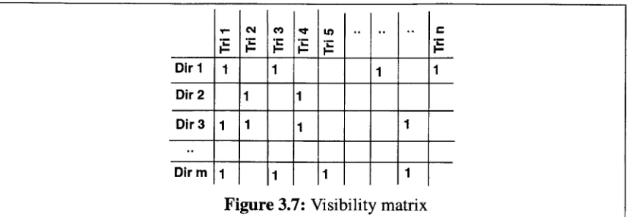
Figure 3.7: Visibility matrix ---
-35
Figure 3.8: Requirement for a set of view directions---
36
Figure 3.9: Subdivision of triangle on Gaussian sphere ---
37
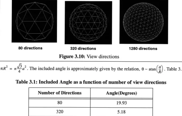
Figure 3.10: View directions ---
-38
Figure 3.11: Point visibility cones ---
-38
Figure 3.12: Rendering pipeline ---
-39
Figure 3.13: Object to view port transformation ---
39
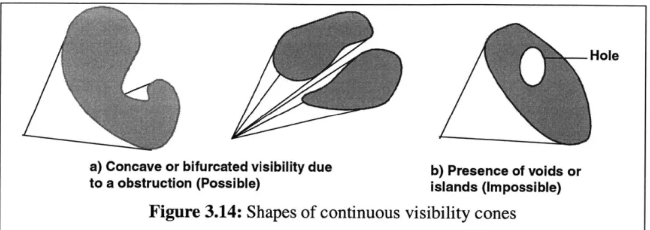
Figure 3.14: Shapes of continuous visibility cones ---
-41
Figure 3.15: Filling holes in visibility cones ---
-41
Figure 4.1: Visibility and Accessibility Cone --- -44
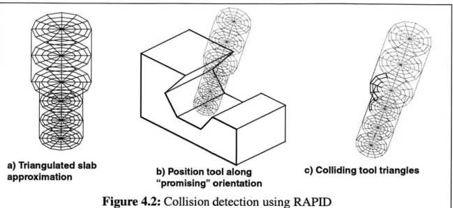
Figure 4.2: Collision detection using RAPID --- -46
Figure 4.3: A tool and its implicit model ---
-46
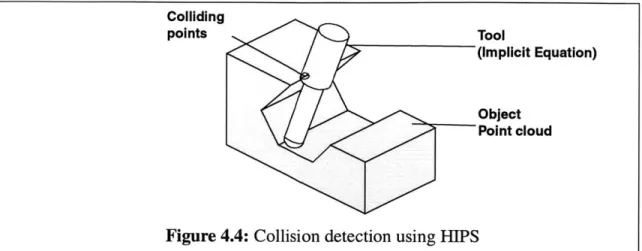
Figure 4.4: Collision detection using HIPS ---
-47
Figure 4.5: Error bounds due to discrete representation ---
47
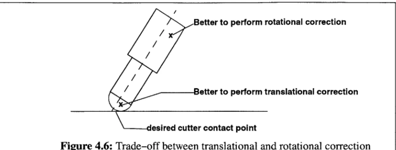
Figure 4.6: Trade-off between translational and rotational correction --- 49
Figure 4.8: Rotational Correction ---
-50
Figure 4.9: Iterative correction in 2D ---
-52
Figure 5.1: Global Roughing ---
-53
Figure 5.2: Visibility for roughing as repeated surface visibility --- 54
Figure 5.3: 3D object and its voxelized model ---
-54
Figure 5.4: Determining "roughing" visibility ---
-55
Figure 5.5: Point visibility cones for roughing ---
-55
Figure 5.6: Determining "central" direction ---
-58
Figure 5.7: Discrete Cone thinning ---
-58
Figure 5.8: Accounting for machine limits --- -59
Figure 5.9: Translational correction for roughing --- -59
Figure 5.10: Access profiling a colliding tool postures --- -60
Figure 5.11: Access information at a slice --- -60
Figure 5.12: Sampling the slice for roughing ---
-61
Figure 5.13: Local discontinuity in the configuration space --- -62
Figure 6.1: Stages in our approach for generating surface finishing toolpaths --- 64
Figure 6.2: Visibility analysis of part with overhang--- 65
Figure 6.3: Tool posture selection --- -65
Figure 6.4: Machining strategy considerations--- -66
Figure 6.5: Machining strip width --- -67
Figure 6.6: Effective cutting shape Vs. Inclination angles --- -67
Figure 6.7: Edgelist determination for a visibility cone --- -68
Figure 6.8: Selection criterion from an edgelist --- -69
Figure 6.9: Orientation assignment using minimum distance heuristic --- 69
Figure 6.10: 3D Translational correction --- -70
Figure 6.10: 3D Translational correction --- -70
Figure 6.11: Collision free access direction --- -70
Figure 6.12: Spacing of cutter contact points --- -71
Figure 6.13: Methods for generating cutter contact points --- -71
Figure 6.14: Drawbacks in collision detection algorithm --- 72
Figure 6.16: Determine maximum subtended angle --- -73
Figure 7.1: Validity of interpolation ---
-75
Figure 7.2: C
1interpolation of position and orientation---
76
Figure 7.3: Determining Bezier control points ---
-77
Figure 8.1: Stages in roughing toolpath generation for Undercut channel--- 80
Figure 8.2: Stages in toolpath generation for vase --- -81
Figure 8.3: NC Simulation and machining the vase --- -83
Figure 8.4: Stages in generating roughing toolpaths for an impeller --- -84
Figure 8.5: Stages in generating roughing toolpaths for a teacup --- -85
Figure 8.6: Stages in generating finishing toolpaths for the "diving board" part --- -87
Figure 8.7: NC Simulation of the finishing toolpaths the "diving board" part --- 88
Figure 8.8: Stages in generating toolpaths for a teacup surface --- 89
8.9: NC simulation of finish machining teacup surface
9.1: Tools, shapes and admissible directions
---9.2: Edge conditions
---9.3: Discrete orientation maps
---A.1: Types of cutters [Michovsky]
---A.2: Overhung and Non-overhung cutting tools----B.1: "Typical" STL representation format
-B.2: "Indexed" STL representation format
---C.1: Need for transition
-and h-andle
---Figure C.2: Transitioning through the relief plane
--Figure D.1: Design and Manufacturing Features [Salomons 1995]
---Figure
Figure
Figure
Figure
Figure
Figure
Figure
Figure
Figure
-- -90
-- -93
-- -94
-- -94
- -102
- -102
- -104
- -105
- -106 - - 107 - - 108List of Tables
List of Algorithms
Algorithm 1: Color encoding the tessellation --- -33
Algorithm 2: Determining visibility information along a view direction --- 34
Algorithm 3: Determining visibility matrix --- -35
Algorithm 4: Gaussian sphere sampling ---
-36
Chapter 1: Introduction
Machining is a broad term to describe removal of material from a workpiece. It covers several processes which can be divided into several categories: cutting, abrasion and non-traditional. Cut-ting involves use of single-point or multi-point cutCut-ting tools with a clearly defined geometry. Abrasive processes involve material removal using small, nonmetallic hard particles having an irregular shape. Non-traditional processes utilize the electrical, chemical, thermal and hydrody-namic methods for material removal. In this thesis, we will use the term machining to describe the milling operation that involves material removal using multipoint cutting tools.
We first describe the importance of machining in today's CAD/CAM in Section 1.1 and the reason for manufacturing industries to increasingly use five axis machines in Section 1.2. Section 1.3 gives an overview of the current state of the art in toolpath generation and reasons out why it is difficult to generate five axis toolpaths that utilize the dexterity of the five axis machine. Inorder to utilize the five axis machines to the fullest extent, we have to look at alternative methods of tool-path generation. With this introduction, we briefly describe our approach in Section 1.4. Section 1.5 outlines the important contributions of the thesis to enable automatic five axis NC toolpath generation.
1.1 Machining in CAD/CAM
The term CAD/CAM implies that an engineer can use computer systems both for designing a product and for controlling manufacturing processes.
Machining is one of the most widely used process to manufacture functional mechanical pro-totypes of parts. We refer to the initial billet of raw material as the stock, the final shape to be machined as the embedded design, and the material to be removed as the delta volume. The delta volume, AV, can be considered to have two portions of interest: the boundary surface, much of which is also the surface of the part, and the internal volume, which constitutes the bulk of the material to be removed. The bulk of the delta volume is removed by a process known as rough machining, or simply, roughing. Roughing is critical to productivity. The surface of the part is usu-ally created by a delicate machining process called finish machining. Finish machining is critical for the functionality of the part. Figures 1.1 (a), (b) and (c) shows the 3D model of a part along with the output at the end of rough and finish machining.
a) 3D model of part b) Rough machining c) Finish machining
pX y
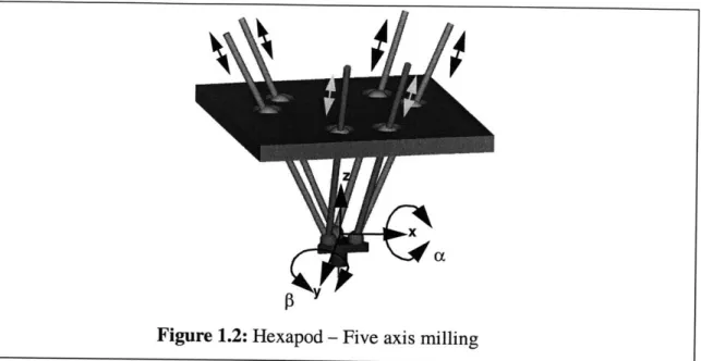
Figure 1.2: Hexapod - Five axis milling
Machining offers many advantages to manufacturing. Firstly, we can achieve closer dimen-sional tolerances than shaping or metal-forming operations. Secondly, we can manufacture parts with internal and external profiles such as sharp corners and flatness requirements. Thirdly, machining is more economical than manufacturing by other processes, particularly if the number of parts desired is relatively small. However, machining is not usually considered a "rapid" proto-typing process because it requires considerable effort and expertise, both intellectual and manual, to plan and operate tools like milling machines and lathes. In recent years this has lead to many attempts to automate machining and integrate it with computer aided design.
1.2 Five axis machines
Manufacturing of parts that have complex contoured regions needs five axis machining capa-bility. Five axis machines have two rotary axes in addition to the standard three translational axes. Figure 1.2 shows a hexapod that has 6 actuators operating on a stuart platform to achieve three translational and two rotational axes at the tip of the cutting tool. Section 1.2.1 gives the reasons for why five axis machines are becoming increasingly popular in manufacturing industries and Section 1.3 summarizes the current state of the art in toolpath generation and Section 1.4 gives the technological challenges associated with generating five axis toolpaths to program the five axis machines.
1.2.1 Need for a five axis machine
In a five axis machine, the tool orientation can be controlled to "access" difficult-to-reach places and machine a surface faster. The ability to reorient the tool relative to the workpiece in mid-cycle enables the machine to mill, drill and tap many different surfaces of a prismatic part, at numerous compound angles, in a single setup. The cuts themselves may demand only X, Y and Z,
but extra axes provides the access. Economic considerations that favor five axis machining over a sequence of three axis operations are given below.
mini-mum radius of curvature of the surface be denoted Pmn. One of the necessary conditions for gouge free contact between a tool and part surface is that the radius of curvature of the tool (ptool) must be smaller than the radius of curvature of the surface (Psurface)- In three axis machining Ptool is a constant. Therefore, for three axis machining the tool is sized based on the criterion ptooi < pm. Whereas in five axis machining, a flat milling tool of radius (Rtool) can be tilted to achieve a wide range of radii of curvature (0 < Ptool < Rtool) that matches the surface curvature. Jerard [Jerrard 91] shows that huge performance gains in machining time can be achieved by selecting five axis machining over three axis machining.
2. The ability to perform complete machining in a single setup reduces part handling and increases manufacturing throughput.
3. Cost savings introduced by reduction in the number of machines, tooling and fixturing to achieve the same end result. The increased access can be used to rework on parts and reduce the value of scrap produced.
The potential cost savings must be weighed against the higher initial investment required for five axis machining capabilities. Now that we have seen the reasons for rapid growth of five axis machining in the manufacturing industries, we will look at the key area of generating toolpaths that utilize the "dexterity" of a five axis machine.
1.3 Five axis toolpath generation
-
existing approaches
The toolpath generator will generate a sequence of tool positions that can be used to command a milling machine to perform the material removal operation. In Section 1.3.1 we highlight the drawbacks inherent in the state of the art commercial five axis toolpath generators. Section 1.3.2 describes the importance of NC verification for generating collision free toolpaths. We give a brief introduction to the "features" approach in Section 1.3.3 and how it has been used in the context of design and manufacturing. After presenting the limitations of extending the feature based approach to five axis toolpath generation, we stress the fact that one has to look at alternate para-digms of toolpath generation for five axis machining.
1.3.1 How commercial systems work today
Commercial CAM systems and feature based design systems are based on 3
degree-of-free-dom cavity machining techniques. 3 dof machining is an extension of 3-axis machining to
com-plex surfaces. Although, axes may end up moving, the search space is not 5-dof The search is still on a 3-dimensional manifold embedded in a 5-space. While many CAM systems like Master-CAM, CAMAX, AlphaCAM and ProManufacture can utilize 5-axis machines, their search space is always limited to three degrees of freedom. The other two degrees of freedom are defined by the orientation mode set by the user. Common modes are surface-normal machining and drive-sur-face machining. In either case, the problem of path generation is reduced to a search conducted entirely on a three dimensional manifold.
The drawback of this limited search is that the CAM system is incapable of preventing gouges and global interference. That responsibility today lies solely with the user. Furthermore, apart from access issues, the user of commercial CAM systems must also perform additional tasks including: selecting a tool, selecting a cutting strategy, and selecting a cutting order. Operation of commercial CAM systems involves considerable operator skill, which is often difficult to come by. It has been argued that for parts of medium complexity, CAD/CAM may be responsible for up to 20% of
Workpiece
Spindle Fixtures
Tool Holder
Cutting portion
a) A real milling tool [Sutherland] b) Workpiece along with fixtures
Figure 1.3: Model of tool and workpiece environments cycle time and a considerably greater fraction of the actual cost [Salmon 96].
1.3.2 NC verification
For the toolpaths to be used in a manufacturing scenario, one has to ensure that there is no col-lision between any portion of the tool and the workpiece. Figure 1.3 (a) shows a model of the tool [Sutherland]. A tool model can include the cutting portion as well as the non-cutting portions such as shank, tool holder and spindle. The workpiece model shown in Figure 1.3 (b) can also be com-plex enough to include the effect of fixtures in addition to the 3D model of workpiece. There are several commercial packages such as Vericut, CGCut and NcVerify that simulate and verify four and five axis milling, drilling and turning. In Section 1.3.2.1 we describe the need for NC verifica-tion in today's manufacturing environment and Secverifica-tion 1.3.2.2 briefly describes the Z-buffer veri-fication. In Section 1.3.2.3, we describe how the current toolpath generation systems place the onus of collision avoidance on the user under the pretext of NC verification. We conclude this sec-tion with the observasec-tion that there is a need for a very fast three dimensional collision detecsec-tion and avoidance algorithm to generate collision free toolpaths.
1.3.2.1 NC verification - needs
In order to generate safe toolpaths for CNC machines it is necessary to check if the toolpaths generated are valid. As the complexity of the machining operation increases, so does the chance for error. NC programming instructions for five axis milling also generally have close tolerance requirements for profiles and surfaces. These factors increase the importance of verifying the NC program. By using NC verification it is possible to identify the following types of errors:
1. Programming inaccuracies due to incorrect toolpath motions and machining the workpiece during the rapid tool motion.
2. Invalid collisions between the tool (cutting portion, tool shank, tool holder and spindle) and workpiece (embedded object and fixtures).
3. Errors in the post-processor output due to bugs in the CAD/CAM program.
1.3.2.2 Z-buffer verification
The most popular approach for verification is the Z-map approach. The Z map model for NC simulation and verification is identical to the Z-buffer approach for hidden surface removal in
computer graphics. The model of the tool, part and the fixtures are loaded into the scene and the tool is swept through the toolpath. The entities are sorted according to the distance from the view-ing point and the entities closest to the view point are rendered. The two dimensional projected view is used to make inferences about collision between the tool and the object. This is a passive system where the user has to identify the collisions and tweak the toolpaths to avoid the collisions. Recently, several commercial packages have implemented the verification system using an extended Z-map model. These packages are powerful to compute the work in progress while machining and export the solid model of the machined part. The solid model of the simulated part can be compared with the model of the designed object to determine uncut and gouging locations in the workpiece. It should be noted that the procedure for correction is still passive because the verification package shows the colliding portions of the workpiece in red and the user should man-ually tweak the G-codes to avoid the collision.
1.3.2.3 How current systems use NC verification
Most of the current toolpath generation systems consider very simple abstractions of the tool and the workpiece. For example, they consider the tool to be an infinitely long, uniform diameter cylinder. This assumption inherently ignores the presence of a larger diameter tool holder and spindle that might possibly come in collision with the workpiece. A workpiece consists of several features and it is imperative to consider the collision of the tool with any feature while generating toolpath for a feature. Moreover, these systems generate toolpaths ignoring global collisions and check for compatibility between local surface geometry and tool curvature to generate local gouge free toolpaths. The task of global collision avoidance is left to the user. Typically, users turn to NC verification systems to visually identify regions of collision. The user must then manually correct the toolpath by tweaking the G-codes or by regenerating the toolpath in the CAM system either with a different drive surface or a different tool tip orientation control curve. This procedure is pas-sive, un-intuitive and iterative. The result is that for complex shapes such as turbine blades, 5-axis toolpath generation can be time-consuming and operator intensive.
1.3.2.4 Collision free toolpaths
An interesting conclusion from Section 1.3.2.3 is the need for an active system that can detect and correct collisions between 3D bodies, namely the tool and workpiece, rapidly. The running time of the collision avoidance routine must be in the order of milli-seconds so that it can be included in the loop of toolpath generation.
The advantages of generating toolpaths using an active system have intrigued several researchers. Li and Lee [Li 94, Lee 95] address this problem and have stressed the importance of a collision detection algorithm in their publications. Li presents an approach for detecting and elimi-nating collisions between a tool and a triangulated object. Lee presents a two phase approach for checking and eliminating collisions between the tool and the machined surface. The approach assumes a specific representation of the workpiece and is hence limited in applicability. Section 1.4 describes the various stages in our modular approach for determining local and global gouge free five axis tool postures.
1.3.3 The "Features" approach
Features can be viewed upon as information sets that refer to aspects of form or other attributes of a part, in such a way that these sets can be used in reasoning about design,
perfor-Hole Pocket
Slot
Figure 1.4: Part along with its features
mance and manufacture of the part or the assemblies they constitute. Figure 1.4 shows some exam-ples of features occurring on a part. A product model can be built by using "design" features and is commonly referred to as design by features or feature based modelling. Design features often dif-fer from application "manufacturing" or "machining" features that are required for process plan-ning.
Machining features are 2-1/2 D shape primitives defined in terms of access directions, and mapped to pre-determined, parametrized cutting paths. Typical CAM systems today require input in the form of these features; in turn, they generate low-level cutting instructions by "fleshing out" the details from the parametrized input. Machining features have proved to be convenient because they characterize the capabilities of machining processes such as 3-axis milling and turning fairly well. For example, the important classes of 3-axis cutting operations are end-milling, face-mill-ing and drillface-mill-ing. The machinface-mill-ing features that correspond to these operations are pockets, faces and holes respectively.
1.3.3.1 Feature extraction
Designing with "design" features overcomes the problem of lack of modelling freedom in the design with "machinable" features approach. Several commercial CAD systems employ this approach. The problem now shifts focus to the procedure for extracting "machinable" features from the "design" feature. This is referred to by researchers as Feature Extraction [Sakurai 90]. Although this is a simple, obvious statement of fact, there is lot of debate and research going on today to make feature extraction a reality [Salomons 1995]. Appendix D lists the several issues that make feature extraction a very tough problem. Although, there has been a lot of promising research in feature extraction in recent years, no commercially viable solution has yet emerged.
1.3.3.2 Feature based five axis toolpath generator
Features are essentially 2 1/2 D entities that work well in prismatic parts. The full extent of manufacturing capabilities of 4 or 5 axis milling machines cannot be efficiently captured by classi-cal features. Inorder to overcome the limitations, several researchers [Srinivasan 99] are working on the development of five axis feature definitions.
In order to make the machining technology more accessible in today's demanding industrial climate, it is necessary to explore other paradigms which may, in the future, overcome the
limita-Figure 1.5: Sample parts for demonstrating concept
tions of existing approaches. The problem assumes a lot of interest today because of the rapid increase in the usage of five axis machines in the manufacturing industry and small changes in the design/manufacturing lead times can produce enormous savings in this multi-billion dollar indus-try.
1.4 How we address the problem
From Section 1.3 we can conclude that it is difficult to generate a "feasible" toolpath quickly from the CAD model of a part. It is mainly because existing systems are extremely time consum-ing, manual and places the onus of collision free toolpath generation to the user. Inorder to auto-mate the process of toolpath generation, we have to look at alternate paradigms for generating five axis toolpaths by studying the problem from its first principles.
1.4.1 Problem formulation
In this thesis, we outline an alternative way of generating multi-axis machining paths directly from the boundary representation of the geometric object. We refer to this as generalized 5-axis
pocket-milling. The goal is simple, and is alluded to by several other researchers in the literature.
We will attempt to generate free-form cutting paths to remove the unnecessary material from the stock while avoiding local and global interference with the embedded part shape. Little effort will be devoted to the organization of toolpaths into formal primitives like features. Instead, the goal will be to harness the dexterity of multi-axis machine tools using access arguments.
In order to demonstrate the functioning of the algorithm, we will generate "feasible" five axis toolpaths for a class of parts from their CAD model for which blind folded application of existing toolpath generation methodologies would fail. I will be considering a class of parts whose normal at a point on the surface intersects another feature on the part. Figure 1.5 shows the parts for which toolpaths will be generated to illustrate the algorithms developed in the thesis.
1.4.2 Outline of our approach
Our approach is to generate toolpaths that sweep the delta volume without colliding with the embedded shape of the part. Avoiding collisions can be viewed alternatively as assuring access, and for this reason, our approach can also be referred to as access-based machining. As far as pos-sible, we make no attempt to aggregate or partition the delta volume into pre-determined shape primitives or features. Figure 1.6 shows the procedure for toolpath generation of existing CAM systems and the system proposed by us in this thesis. Our approach for both roughing and finishing
Feature Extraction Today's CAM
Model p. Machining Toolpath
Feature generation
What we want to do
Figure 1.6: Outline of our approach for toolpath generation
consists of three stages: visibility computation, legal posture definition and path interpolation. In the first stage, we use the concept of visibility to determine from which directions a point in the delta volume or on the boundary surface is likely to be accessible to an observer located out-side the convex envelope of the object. The set of visible directions for a point is referred to as the point visibility cone. The point visibility cone can be used to determine the most "promising" direction to access the point. The procedure for extracting a direction from among the several directions proposed by the visibility cone is different for roughing and finishing. The difference is attributed to the choice of machining strategy selected for roughing and finishing.
Visibility does not ensure accessibility because it cannot account for the diameter of the tool, the tool-holder or the spindle. We describe the second stage of our process referred to as access profiling. We start from the first guess of visibility analysis and determine the size and orientation of the cutting tool that are guaranteed to access a required point in the delta volume without any interference. The major task in posture definition is a local search in the neighborhood of the direc-tion first suggested by visibility analysis. The output of the posture definidirec-tion step is a set of valid tool postures for every sample point in the delta volume or on the boundary surface.
Finally, all that remains to be done in the third stage is to connect the valid postures into a valid continuous toolpath. This is not a trivial task because the tool must not interfere with the part while interpolating between valid postures. In Chapter 7 we discuss this problem and show how it can be avoided by incorporating the visibility information. Further, we simulate the tool motion along the interpolated toolpath and correct for collisions within the loop of path generation. Figure 1.7 summarizes the three steps in our approach. After covering the theoretical and algorithmic
Chapter 3: Compute
visi-bility cones Chapter 4: Accessibility deter- Chapter 7: Link into toolpath
mination
bases of our approach in Chapters 3 to 7, we show the application of these techniques to example components in Chapter 8. We conclude the thesis with a summary of the research done along with the future work in Chapter 9.
Depending on the information needed for an application, the users can add constraints to this modular five axis toolpath generation methodology or terminate the procedure after determining the access postures in the second stage. For example, Taejung [Taejung 01] proposes a method for determining the toolpath optimal in the machine actuator space based on tool access postures at various points on the surface.
1.5 Contributions
In this thesis we present several algorithms and heuristics to generate roughing and finishing toolpaths by using "accessibility" of the tool as a driving constraint for the problem. In this Section we will summarize our major contributions.
1. We have developed a framework for generating five axis toolpaths, start to finish, com-pletely automatically from the CAD model of a part. In order to develop the framework we used some of the interesting concepts developed by researchers in the field. However, these concepts served as "islands" that addressed only a part of the larger problem. We have built the "bridges" across the "islands" and in the process invented new concepts and fast algo-rithms that enable automatic five axis toolpath generation.
2. We have invented an overall scheme based on visibility in place of accessibility. The reason being accessibility information is difficult and time consuming to generate. The premise for our approach is that for non-overhung tools (Appendix A) accessibility is a subset of
visi-bility. A new method for computing "dense" visibility information rapidly using graphics
hardware has been presented in Chapter 3. This is a practical approach to C-Space planning [Lozano-Perez 83].
3. We have developed new algorithms that process copious amounts of visibility information to generate five axis tool posture assignments for a set of cutter contact points. The driving force behind these algorithms is that visibility closely matches accessibility and can be used to arrive at a "promising" access direction. Algorithms to select the "promising" access directions for roughing and finishing have been presented in Chapter 5 and 6 respectively. 4. Visibility assumes a ray of light to reach a point but accessibility is for a tool of finite
geom-etry. We can expect collisions to occur between the workpiece and the tool positioned along the "promising" orientation. We have incorporated methods from computational geometry to process the results of a collision detection algorithm to move the tool away from
colli-sion. The algorithms to convert the "promising" access direction to a "valid" access direc-tion have been presented in Chapter 4.
The algorithms outlined in this thesis make it possible, for the first time, to generate 5-axis CNC toolpaths automatically from a CAD file. The algorithms have been implemented and tested on several parts.
Chapter 2: Background
In this chapter, we summarize the evolution of the research in the areas of access based tool-path generation, collision avoidance, NC verification and feature based machining. We conclude the chapter by presenting a short note on how the issues mentioned above are handled in commer-cial CAD/CAM software.
2.1 Review of research on Access based approaches
The problem of tool access has been approached from both, a solids perspective, and a surface perspective. Seminal work in the area of visibility and visibility maps was performed by Chen [Chen 92] and Woo [Woo 94]. They introduced the concept of visibility cones for points on a workpiece, which can be mapped on to the unit sphere to create a Gaussian Map. The same authors also show how the Gaussian projection can be extended with a central projection to manipulate access information and minimize setups. The idea of Gaussian maps was used by Wuerger and Gadh [Wuerger 95] to evaluate the separability of dies. The concept of access is also handled in a feature-based approach in [Sarma 96]. The ideas of a visibility cone have influenced surface machining as well. Lee [Lee 95] uses a convex hull based approach to approximate local visibility. An innovative approach to surface accessibility is presented in [Elber 94], in which convex sur-faces are mapped to a space in which they become planar. Obstacles to the surface are also mapped into this space, and toolpath generation is carried out in a 3D world. The paths are then inverse mapped back to the original space to obtain 5-axis toolpaths. [Spyridi 90, Henderson 96, Tan-gelder 96, Gaines 97, Stage 97] explore other concepts pertaining to accessibility.
In recent years, the problem of determining tool accessibility has been approached from the perspective of computer graphics. Spitz [Spitz 00] presents a very interesting and a practical method for performing accessibility analysis using computer graphics hardware. The emphasis of their work is on computing accessible directions for tactile probes used in 3-D digitization with coordinate measuring machines. [Morishige 99] presents an approach for toolpath generation using three dimensional configuration space. The publication highlights the importance of three-dimensional configuration space for determining the optimal cutter location data and proposes an algorithm to determine the three dimensional configuration space.
2.2 Review of research on Collision avoidance schemes
Collision detection procedures determine whether or not two entities are in a state of contact, and are useful in a range of computational geometry applications. A range of collision detection procedures are known today for representations such as convex polytopes and triangulated surface meshes. In addition to determining the boundary of collision of two shells, we need the depth information for computing the force or displacement necessary to perform haptic rendering or col-lision avoidance during toolpath generation. [Rameau 93] refers to this as penetration analysis.
Lin and Canny present an efficient method of calculating collisions between convex polyhedra [Lin 93]. The method takes advantage of temporal and spatial coherence and operates especially well when the objects rotate at a speed less than one half a rotation per collision detection cycle. In addition to determining a collision event, the method gives proximity information. Application of
the Lin-Canny method is limited to convex objects. Methods to break non-convex objects into a union of convex object could be used, but the additional complexity of these methods limits the practicality of such an approach. I-Collide is a collision detection package written by the compu-tational geometry group at University of North Carolina. I-Collide extends the Lin-Canny approach to an n-body simulation with penetration depth information; however, the objects of the collision detection are limited to convex polyhedra [Cohen 95], and therefore suffer the same lim-itations of the Lin-Canny method. Mirtich has improved upon the Lin-Canny approach with the V-Clip collision detection method, which enhances the robustness of the Lin-Canny approach and adds penetration depth calculation [Mirtich 98]. Again, the technique deals with convex objects so that non-convex objects must first be decomposed into the union of convex objects.
Triangle set methods represent the surface of each object as a set of triangles and report whether or not any triangle of one set intersects any triangle of the other set in each collision detec-tion query. Triangle sets are capable of representing both convex and non-convex objects. Fur-thermore, the methodologies do not even require that the object be a coherent solid; any set of triangles is applicable. To increase the efficiency of the triangulated collision detection methods, a bounding volume hierarchy is used. Gottschalk et al. introduce the use of Oriented Bounding Boxes in triangle set methods [Gottschalk 96], and Held et al. propose the use of k-Discrete Ori-ented Polytopes [Held 96]. These bounding volumes and their associated bounding volume hierar-chical trees enable the collision detection technique to compute the solution more quickly in the average case.
Ho et. al. [Ho 1999] presents an interesting approach for collision detection using a heteroge-neous representation consisting of an ensemble of implicit equations on the probe side and a cloud of points on the part side. The authors also present a rationale as to why this system has fast perfor-mance and how depth information is yielded naturally.
2.3 Review of research on NC simulation and error detection
Simulation of NC machining requires algorithms to model the embedded part, workpiece and the swept volume of the tool. The workpiece model need to be updated dynamically by subtracting the swept volume of the tool. Moreover, in addition to the algorithms being fast the model must be accurate to within several order of magnitude of the desired nominal tolerance of the machined part. The problem of simulation has been approached from a solid modelling perspective as well as a graphics perspective with true solid update facility.
A mathematical approach to simulation based on set theory was first presented by Gossard [Gossard 78]. The feasibility of application of Constructive Solid Geometry to simulation was studied by Voelcker [Voelcker 81] and Fridshal [Fridshal 82]. The solid modelling approach is computationally expensive and requires 0(n4
) calculations where n is the number of tool positions
to be verified. Each tool position involved computation of intersection between the toolpath enve-lope and workpiece. In order to decrease the computation time, localization techniques and local updating methods were studied by Woodwark [Woodwark 84] and Bronsvoort [Bronsvoort 89]. Choi [Choi 98] observes that the main problem with the solid modelling approach is intensive nature of verifying the equivalence of the finished workpiece and the desired part.
The Z map model for NC simulation and verification is identical to the Z buffer approach for hidden surface removal in computer graphics. This concept was first introduced by Anderson [Anderson 78] and several researchers have provided for different implementations. Van Hook
[Van Hook 86] developed another version of an "extended Z map" using depth elements called dexels. Most early systems for simulation were three axis based, or were relatively limited in their applicability of predicting gouging in five axis machining. Recognizing this problem, a few researchers in recent years have looked into the simulation of multi-axis cutting: [Wang 86, Oliver 86, Jerrard 89b, Jerrard 91]. Recently, there have been several commercial packages (CGCut, Ver-iCut and NC Verify) that can perform NC verification using Z maps. These packages can identify the amount of undercut or uncut material in the workpiece and some even export the solid model of the intermediate solid.
2.4 Commercial CAM systems
Most commercial CAM systems, including purported 5-axis systems, are based on 3
degree-of-freedom (as opposed to 3 axis) cavity machining techniques. We use this term because, while
many CAM systems like MasterCAM, CAMAX, AlphaCAM and ProManufacture can utilize 5-axis machines, their search space is always limited to three degrees of freedom. The other two degrees of freedom are defined by the orientation mode set by the user. Common modes are sur-face normal machining and drive sursur-face machining. In either case, the problem of path generation is reduced to a search conducted entirely on a three dimensional manifold. The drawback of this limited search is that the CAM system is incapable of preventing gouges and global interference. That responsibility today lies solely with the user. Furthermore, apart from access issues, the user of commercial CAM systems must also perform additional tasks including: selecting a tool, select-ing a cuttselect-ing strategy, and selectselect-ing a cuttselect-ing order. As a result, 5-axis CAM machinselect-ing is still very much an acquired skill today.
Growing awareness of these problems has lead to recent interest in a new technology called Generative NC. SDRC has recently offered an early version of its Generative NC package. SDRC's generative NC system, however; is still based on 3-axis machining, and still requires human input for access-direction selection and tool selection. This proposal deals with the theoret-ical and practtheoret-ical issues in 5-axis generative NC. There are fundamental theorettheoret-ical issues that need to addressed before such a system can be created. Yet, without such research, it will be diffi-cult to make full and efficient use of advanced 4-axis, 5-axis and multi-axis machine tools like the Hexapod.
2.5 Robotics
The research that we present here has some parallels to previous work in robot path planning as well. The problems of visibility and accessibility have been addressed in great detail by a num-ber of researchers. Lozano-Perez first attempted to build automatic robot navigation systems [Lozano-Perez 83]. The concept of a configuration space evolved through a series of papers in the early 80's [Udupa 77, Lozano-Perez 81, Lozano-Perez 83]. In the latter paper, Lozano-Perez also introduced the concept of cell decomposition, which is loosely analogous to the voxelized approach presented here. A comprehensive description of later developments in robot planning is presented in [Latombe 91]. An important difference between robotics and machining, however, is that while robotic path planning is concerned with accessing particular points in the configuration space, machining is concerned with sweeping all the points within and on the boundary of the delta volume.
2.6 Review of research on Feature based machining
Although this thesis does not build on feature research, we present a survey of research on fea-tures for completeness.
The concept of machining features has been an important step in the development and under-standing of manufacturing planning. Machining features have the following advantages: 1) fea-tures are a convenient decomposition of machining into handleable units for high level planning; 2) toolpath generating algorithms can be developed and implemented up-front; 3) since features fit the object oriented model well, tool selection and cutting parameter selection can be linked cleanly to knowledge bases; 4) machining features implicitly define access directions and accessi-bility volumes.
The first mention of features is probably by Krypianou [Krypianou 80]. The concept of manu-facturing features first appears in [Arbab 82]. Arbab points out the similarity between the boolean difference operation in constructive solid geometry and the material removal in machining. This lead to the idea of destructive solid geometry (DSG), a design input methodology later refined in a series of papers: [Hummel 86, Kramer 88, Turner 88, Cutkosky 88, Shah 88 and Gindy 89]. In DSG, the user defines a "stock" and subtracts primitives (features) to define the part. The develop-ment of process planning systems for machining has closely followed the developdevelop-ment of features technology. Beginning with early work by Nau [Nau 86], Hayes [Hayes 89], Anderson [Anderson 90] and Cutkosky [Cutkosky 90], to more recent papers by [Yut 95, Gupta 95 and Sarma 96], the use of features has become better understood and more widespread.
Meanwhile, there has been interesting research in feature extraction in recent years. Seminal work on feature recognition was done by Woo [Woo 82]. Later, Joshi [Joshi 88] used graph based heuristics to extract features from adjacency graphs. [Dong 88, Sakurai 90, Finger 90 and Vanden-brande 90] made important contributions to the field. Kim extended Woo's work on convex decomposition [Kim 90]. Gadh introduced the concept of depth filters for feature recognition [Gadh 92]. Nau et. al. introduced the idea of generating alternative, optimal machining volumes in [Nau 92]. Recently, Regli has reported a promising new approach to feature extraction in his Ph. D. Dissertation [Regli 95]. His approach is based on the extrapolation of "maximum cover fea-tures" for 3-axis machining from the faces of a boundary representation. In general, most feature based approaches have been limited to 3-axis machining.
Features are essentially 2 1/2 D entities that work well in prismatic parts. The full extent of manufacturing capabilities of 4 or 5 axis milling machines cannot be efficiently captured by classi-cal features. Inorder to overcome the limitations, several researchers [Srinivasan 99] are working on the development of five axis feature definitions.
Chapter 3: Visibility Analysis
A key idea in delta volume machining is collision avoidance between the tool and the work-piece. Collision avoidance can be viewed alternatively as access assurance. In other words, how can the cutting tool be oriented to access the delta volume without intersecting with the embedded design? An interference free tool direction will be referred to as an access direction. For a given point in the delta volume of the object, the access direction may not be unique. We therefore talk of access cones, which are contiguous sets of access directions. Section 3.1 describes the computa-tional complexity associated with the procedure for determining the access information of points in the delta volume. We then propose a method of computing the access information in stages by using the fact that visibility is a necessary condition for accessibility for most tools (described in Appendix A). We can therefore also talk about visibility directions and visibility cones, which are conservative approximations of accessibility directions and accessibility cones respectively because visibility ensures that an infinitely long tool of zero diameter can access the region of the delta volume. Section 3.2 describes the evolution of the visibility concept for 3-axis applications and difficulty in extending the results for 5-axis applications. Section 3.3 briefly describes the complexity and time consuming nature of a software based approach to determining visibility. We then explain our procedure for rapidly determining the 5-axis visibility information using graphics hardware in Section 3.4. In Sections 3.5 and 3.6 we address the various implementation issues such as selection of number of viewing directions, relation between the size of the part and the view port and an order of magnitude estimate about the memory requirement for generating the visibility information.
3.1 Difficulty of access determination problem
For the purpose of machining accessibility is defined as follows: A point P on surface S is accessible by a tool oriented along orientation 0, if and only if the cutting portion of the tool is in contact with point P and the tool is not interfering with the embedded design object. The orienta-tion from which a point can be accessed by a tool can be mapped to a point on the surface of a sphere (S2) centered at the origin. Maps of orientation vectors to S2 are commonly referred to as Gauss Maps. For a point in R3 there are infinitely many orientations from which it could be accessed by a tool. Clusters of visibility or accessibility directions become patches on the surface of the Gauss Sphere. The patches on the Gauss map forms a cone with its apex at the origin and we refer to them as visibility and accessibility cones respectively. As we have defined them, these cones capture the directions of interference free visibility or accessibility for a point in three dimensional space, and we will refer to such cones as point-visibility or point-access cones. While generating toolpaths, the tool should be given an orientation along which it should be aligned at every point. In order to generate interference free toolpaths, this orientation should be one of the accessible directions for that point. Therefore determining point access cones is of real importance in automating the toolpath generation for machining.
Figure 3.1 (a) shows the point access cone for a point in R3 space. The point access cone is the entire sphere because the point can be freely accessed from all the orientations. Figure 3.1 (b)
a) Access cone of point in R3
S
b) Access cone of point on a plane
S
c) Access cone of point in a 3D object
Figure 3.1: Point access cones
shows the point access for a point lying on a plane. The point access cone is the upper hemisphere formed by slicing the sphere with the plane because the point can be reached from along the orien-tations lying above the plane. Figure 3.1 (c) shows the point access cone for a point lying in an arbitrary object. In the subsequent chapters, we explain the importance of access cones in assign-ing tool postures for a set of consecutive cutter contact points.
3.1.1 Point and region access cones
The access direction can be determined by using a trial and error approach by positioning the tool along random orientations to reach a point. It is evident that this approach is very time con-suming and not reliable. The access cone for the point can be determined as an union of valid access directions. [Tangelder 96 & Roberts 96] use the Minkowski operation to generate accessi-bility cones. Unfortunately, Minkowski methods tend to be computationally expensive. Our approach is to find the approximate access direction, but a good estimate, very efficiently.
Access can also be generalized for regions. An access cone for a region, which we will refer to as a region-access cone, is the intersection of the point-access cones for all the points in the region. The access cone for a region R can be defined formally in terms of point access cones as