Publisher’s version / Version de l'éditeur:
Proceedings of the Global Conference on Global Warming-2009, 2009
READ THESE TERMS AND CONDITIONS CAREFULLY BEFORE USING THIS WEBSITE. https://nrc-publications.canada.ca/eng/copyright
Vous avez des questions? Nous pouvons vous aider. Pour communiquer directement avec un auteur, consultez la
première page de la revue dans laquelle son article a été publié afin de trouver ses coordonnées. Si vous n’arrivez pas à les repérer, communiquez avec nous à [email protected].
Questions? Contact the NRC Publications Archive team at
[email protected]. If you wish to email the authors directly, please see the first page of the publication for their contact information.
Archives des publications du CNRC
This publication could be one of several versions: author’s original, accepted manuscript or the publisher’s version. / La version de cette publication peut être l’une des suivantes : la version prépublication de l’auteur, la version acceptée du manuscrit ou la version de l’éditeur.
Access and use of this website and the material on it are subject to the Terms and Conditions set forth at
Efficiency and environmental impact analyses of biomass based power
production systems
Colpan, C. Ozgur; Hamdullahpur, Feridun; Dincer, Ibrahim; Yoo, Yeong
https://publications-cnrc.canada.ca/fra/droits
L’accès à ce site Web et l’utilisation de son contenu sont assujettis aux conditions présentées dans le site LISEZ CES CONDITIONS ATTENTIVEMENT AVANT D’UTILISER CE SITE WEB.
NRC Publications Record / Notice d'Archives des publications de CNRC:
https://nrc-publications.canada.ca/eng/view/object/?id=56dfb737-93be-4d66-9bd3-aa30b74b15e5 https://publications-cnrc.canada.ca/fra/voir/objet/?id=56dfb737-93be-4d66-9bd3-aa30b74b15e5EFFICIENCY AND ENVIRONMENTAL IMPACT ANALYSES OF BIOMASS BASED POWER PRODUCTION SYSTEMS
C. Ozgur Colpan1, Feridun Hamdullahpur1, Ibrahim Dincer2 and Yeong Yoo3
1
Mechanical and Aerospace Engineering Department, Carleton University 1125 Colonel By Drive, Ottawa, Ontario, Canada K1S 5B6
2
Faculty of Engineering and Applied Science, University of Ontario Institute of Technology, 2000 Simcoe Street North, Oshawa, Ontario, Canada L1H 7L7
3
National Research Council of Canada, Institute for Chemical Process and Environmental Technology, Ottawa, Ontario, Canada, K1A 0R6
ABSTRACT
In this paper, conventional and advanced biomass fueled power production systems are compared in terms of efficiency and greenhouse gas emissions. The conventional system mainly consists of a biomass combustor and a steam turbine; whereas the advanced system mainly includes a biomass gasifier and a solid oxide fuel cell (SOFC). A heat transfer model of the SOFC and thermodynamic models for the other components of the systems are used to find the performance assessment parameters of the systems. These parameters are taken as electrical and exergetic efficiencies. In addition, specific greenhouse gas emissions are calculated to evaluate the impact of these systems on the environment. The results show that the SOFC and biomass gasification system has higher electrical and exergetic efficiencies and lower greenhouse gas emissions.
Keywords: biomass, SOFC, gasification, steam turbine, greenhouse gas, energy, exergy, efficiency 1. INTRODUCTION
There has been an increasing interest in converting biomass to a product gas by various methods for using it as a fuel source in power production systems. These methods include thermochemical, biochemical, and mechanical extraction methods. Thermochemical conversion methods may be classified as combustion, gasification, pyrolysis, and liquefaction. Biochemical conversion methods are fermentation and anaerobic digestion. The last method is mostly used to produce bio-diesel with esterification. Today’s technology of converting biomass to electricity for small scale applications is mostly based on combustion of feedstock to raise steam that is used to drive the steam turbine (Mitchell et al., 1995). However, this system has low efficiency, e.g. typically 6-8% (Pritchard, D., 2002). Other current technologies include externally fired gas turbines and integrated gasification combined cycles (Franco and Giannini, 2005). Recently, the biomass-fuelled integrated SOFC system has been identified as one of key energy technologies for the future since it combines the merits of renewable energy sources and hydrogen energy systems.
Biomass gasification is a thermochemical conversion technology where fuel is converted into a gas mixture called syngas, but also contaminants. The composition of this gas mixture depends on the fuel, e.g. wood and municipal solid waste, gasifier type, e.g. downdraft, updraft, and fluid bed, gasification agent, e.g. air, oxygen, and steam, and other operating parameters of the gasifier, e.g. temperature and pressure. There are two types of gasification processes: autothermal and allothermal. In autothermal gasification, heat is provided by partial oxidation that takes place within the gasifier; whereas in allothermal gasification, an external source supplies the heat needed for gasification reactions.
The SOFC is one of the high temperature fuel cells that can operate in temperatures ranging from 500 °C to 1000 °C depending on the manufacturing type, e.g. electrode-supported and electrolyte-supported. SOFC has several advantages over low temperature fuel cells, e.g. proton exchange membrane fuel cell, such as: being simpler in design concept since there is no liquid phase, fuel flexibility, internal reformation of the gases, and integrability with other systems, e.g. gas turbine and gasifier. However, fuel containing carbon and sulphur can cause problems related to carbon deposition and sulphur poisoning, respectively. In addition, there are challenges with construction and durability due to the high operating temperature.
Researches on analysis of integrated biomass fueled SOFC systems have increased recently. Panopoulos et al. (2006a, 2006b) investigated the integration of a SOFC with an allothermal biomass gasifier using steam as the gasification agent. They found the electrical efficiency of the system as 36% and exergetic efficiency as 32%. Cordiner et al. (2007) studied the integration of a downdraft gasifier with a SOFC. They calculated the electrical efficiency of the system as 45.8%. Athanasiou et al. (2007) analyzed the integrated SOFC, steam turbine and gasifier system. They found the electrical efficiency of the system as 43.3%. Omosun et al. (2004) compared different gas cleanup types to be used in biomass gasification and SOFC system. Their study showed that hot gas cleanup should be selected for better performance and
enriched oxygen are used as the gasification agents. In another study by Colpan et al. (2009b), different technologies including the internal combustion engine, the gas turbine and the SOFC are compared in terms of performance and greenhouse gas reduction to be used in a landfill site. Their study showed that the SOFC shows higher performance and greenhouse reduction compared to the other systems studied.
In this study, a conventional biomass fueled power production system, i.e. a steam turbine system using the heat recovered from the combustion of biomass, is compared with an advanced biomass gasification and SOFC system in terms of efficiency and environmental impact. Electrical and exergetic efficiencies and specific greenhouse gas emissions are calculated for performance and greenhouse gas emission comparisons, respectively.
2. DESCRIPTION OF THE SYSTEMS
A conventional biomass fueled power production system (System-I) and an advanced biomass gasification and SOFC system (System-II) are studied. In both of these systems, a forced drying system is used to evaporate the moisture completely in System-I and bring the moisture content to a reasonable level according to the gasifier design in System-II.
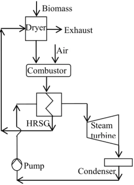
System-I consists of a dryer, a combustor, a heat recovery steam generator (HRSG), a steam turbine, a condenser and a water pump, as shown in Figure 1. In this system, the dried biomass and air enters the combustor. The gas mixture produced from this combustion process supplies heat to the HRSG where steam is produced. The gas mixture exiting the HRSG enters the dryer to supply the required amount of heat for the drying process and then it is emitted to the atmosphere. The steam produced in HRSG enters the steam turbine where the power is produced. The exit stream from the steam turbine enters the condenser and some amount of heat is rejected to the environment. The condensed liquid enters the pump and then it is sent back to the HRSG.
Fig. 1. Schematic of the System-I (a conventional biomass fueled power production system using steam turbine)
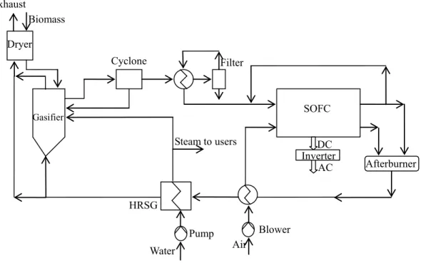
A schematic of the integrated biomass gasification and SOFC system is shown in Figure 2. In the gasification subsection, steam is selected as the gasification agent and external heat is supplied by the recirculation of the depleted streams from the SOFC. The gas mixture produced by gasification, i.e. syngas, has generally high level of contaminants to be used directly in the SOFC. A gas cleanup system has to be used to clean the syngas according to the SOFC impurity levels not to cause any degradation in the fuel cell. For this study, a hot gas cleanup is preferred to be compatible with the gasifier exit and SOFC inlet streams. The cleaned syngas enters the SOFC, where the electricity is generated. It should be noted that depleted fuel stream can be recirculated to adjust the steam to carbon ratio in case there is a carbon deposition problem in the SOFC. The fuel and air streams exiting the SOFC enter the afterburner to burn the unused fuel and increase the temperature of these streams. The mixture leaving the afterburner supplies heat to the following components respectively: the blower used to supply air for the SOFC, the HRSG used to produce steam for the gasifier and the steam users, and the dryer. After exiting the dryer, this gas mixture is emitted to the environment.
Biomass Dryer Exhaust Air HRSG Pump Condenser Combustor Steam turbine
Fig. 2. Schematic of the System-II (an advanced integrated biomass gasification and SOFC system)
3. ANALYSIS
In the modeling of the conventional biomass fueled power production system, i.e. System-I, thermodynamic principles and laws are applied to the components of the system. It is assumed that complete combustion is achieved using 100% theoretical air, i.e. stoichiometric mixture. The heat recovered from the HRSG is first calculated applying an energy balance around the control volume enclosing the HRSG. Using the isentropic efficiencies of the components and the thermodynamic relations, steam produced in the HRSG is then calculated. Finally, using these finding, the power output of the steam turbine, power demand for the pump, and the net power output of the system are calculated.
For the SOFC, the transient heat transfer model developed by Colpan (2009) is used. The approach and main features of this model are as follows: A control volume around the repeat element found in the middle of a planar SOFC stack is taken. It is assumed that the other repeat elements show the same characteristics with this repeat element. The solid structure, i.e. electrodes, electrolyte, and interconnects, is modeled in 2-D; whereas the air and fuel channels are modeled in 1-D. Since the gases flow with low velocity to obtain high fuel utilization, it is assumed that fully developed laminar flow conditions are achieved at the air and fuel channels. Natural convection at the heat-up stage, forced convection at the start-up stage, conduction heat transfer between the solid parts, and all the voltage losses, i.e. activation, concentration, and ohmic, are taken into account in the modeling. The input parameters of this model are cell voltage, Reynolds number at the fuel channel inlet, excess air coefficient, temperature at the air and fuel channel inlets, pressure of the cell, molar gas composition at the air and fuel channel inlets, and the geometrical dimensions of the SOFC. The output parameters are the current density, temperature, molar gas composition, and carbon activity distributions, the heat-up and start-up time, the fuel utilization, the power output and the electrical efficiency of the cell. This model is validated with IEA benchmark test (Achenbach, 1996) and Braun’s model (Braun, 2002).
In modeling the integrated SOFC and biomass gasification system, i.e System-II, firstly, the syngas composition and the external heat needed for the gasifier are calculated by solving the set of equations derived from the thermodynamic modeling of the gasifier. These equations include three atom balances, two chemical equilibrium relations and the energy balance around the control volume enclosing the gasifier. Secondly, using the syngas composition and the heat transfer model of the SOFC, number of the SOFC stacks, molar flow rate of gases at the inlet and exit of the air and fuel channels, temperature at the exit of the air and fuel channels, and power output of the cell are found. Thirdly, combining the outputs of the gasifier and SOFC models, the molar flow rate of the dry biomass is calculated. Fourthly, applying thermodynamic principles to the components of the system, the enthalpy flow rate of all the states are calculated. Finally, using the laws of thermodynamics, work input to the auxiliary components, i.e. blower and pump, and net power output of the system are calculated.
Biomass Gasifier Cyclone Filter SOFC Dryer Afterburner Blower Exhaust Air HRSG Pump Inverter DC AC Water Steam to users
Electrical efficiency and exergetic efficiency are selected as the performance assessment parameters. Electrical efficiency, which is shown in Eq. (1), is the ratio of the net power output of the system to the lower heating value of the fuel. In defining the exergetic efficiency, it is necessary to identify both a product and a fuel for the system being analyzed. The product represents the desired output produced by the system. The fuel represents the resources expended to generate the product. This efficiency can also be written in terms of the total exergy destructions and losses within the system, as shown in Eq. (2).
LHV fuel n system net W el = ⋅ ) ( η (1) F x E L x E D x E F x E P x E + − = = 1 ε (2)
Environmental impact of these systems can be assessed calculating the specific greenhouse gas emissions, which is defined as the ratio of the GHG emission from the system to the net power output of the system. From the viewpoint of energy and environment, the lower the ratio is, the more environmentally friendly the system is.
system net W GHG m ) ( = σ (3)
The input data used in the simulations of the System-I and System-II are given in Table 1.
4. RESULTS AND DISCUSSION
The models discussed in Section 3 are used for simulating the performance and environmental impact of the System-I and System-II using the data given in Table 1. The results and discussion of these simulations are given in this section.
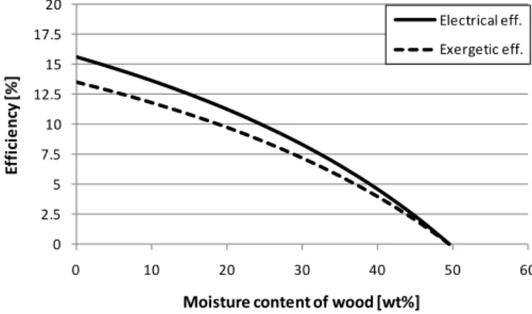
One of the most important factors affecting the performance of the System-I is the moisture content of the biomass. The more moisture content of the biomass is, the more energy demand for the dryer is. Hence, steam produced in the HRSG decreases with an increase in the energy demand of the dryer; which in turns decreases the power produced in the steam turbine and the electrical and exergetic efficiencies of the system. As shown in Figure 1, as the moisture content of the wood increases from 0% to 50%, electrical efficiency of the system decreases from 15.6% to 0%; whereas exergetic efficiency of the system decreases from 13.5% to 0%.
0 2.5 5 7.5 10 12.5 15 17.5 20 0 10 20 30 40 50 60 E ff ici e n cy [ % ]
Moisture content of wood [wt%]
Electrical eff. Exergetic eff.
Table 1. Input data
Environmental temperature 25 °C
Type of biomass Wood
Ultimate analysis of biomass [%wt dry basis] 50% C, 6% H, 44% O
Moisture content in biomass [%wt] 30%
Exhaust gas temperature 127 °C
System-I
Conditions of the steam entering the steam turbine 20 bar (saturated)
Pressure of the condenser 1 bar
Isentropic efficiency of the steam turbine 80%
Isentropic efficiency of the pump 80%
Electricity generator efficiency 98%
System-II
Moisture content in biomass entering the gasifier [%wt] 20% Temperature of syngas exiting the gasifier 900 °C Temperature of steam entering the gasifier 300 °C
Molar ratio of steam to drybiomass 0.5
Number of cells per SOFC stack 50
Temperature of syngas entering the SOFC 850 °C
Temperature of air entering the SOFC 850 °C
Pressure of the SOFC 1 atm
Cell voltage 0.7 V
Reynolds number at the fuel channel inlet 1.2
Excess air coefficient 7
Active cell area 10x10 cm2
Number of repeat elements per single cell 18
Flow configuration Co-flow
Manufacturing type Electrolyte-supported
Thickness of the air channel 0.1 cm
Thickness of the fuel channel 0.1 cm
Thickness of the interconnect 0.3 cm
Thickness of the anode 0.005 cm
Thickness of the electrolyte 0.015 cm
Thickness of the cathode 0.005 cm
Pressure ratio of the blowers 1.18
Isentropic efficiency of the blowers 0.53
Pressure ratio of the pump 1.2
Isentropic efficiency of the pump 0.8
Inverter efficiency 0.95
In System-II, the syngas composition is first calculated as: 2.08% CH4, 42.75% H2, 25.80% CO, 9.44% CO2
and 19.93% H2O. Using this composition and the data given in Table 1, the SOFC model is simulated. It is
found the fuel utilization of the SOFC is 82%. The current density distribution is shown in 2. According to this figure, the average current density of the cell is 0.253 A/cm2 for the cell operating voltage of 0.7 V. At this point, the carbon deposition possibility at the SOFC has to be investigated. For this purpose, the carbon activity distribution through the flow direction is calculated to check if the carbon activity exceeds 1 for any locations. In general, the carbon deposition possibility is more severe at the fuel channel inlet. This fact can also be followed in Figure 2. It can also be seen from this figure that carbon activity is less than 1 for all the locations; hence there is no carbon deposition problem and it is not necessary to recirculate the depleted fuel.
Figure 3 shows the temperature distribution of the SOFC when the system reaches at the steady-state condition. As can be seen from this figure, there is a sudden temperature drop at the x direction, i.e. flow direction, due to the endothermic steam reforming reaction and then the temperature increases due to exothermic electrochemical and water-gas shift reactions. This figure also shows that there is not a significant temperature change at the y direction, i.e. cell thickness direction. At the exit of the fuel and air channels, the temperatures of these exits are both found as 1000 °C.
0 0.1 0.2 0.3 0.4 0.5 0.6 0.7 0.8 0.9 1 0 0.05 0.1 0.15 0.2 0.25 0.3 0.35 0.4 0.45 0.5 0 2 4 6 8 10 C ar b o n ac ti v it y C u rr e n t d e n si ty [ A /c m 2] Distance to inlet [cm] Current density Carbon activity
Fig. 2. Current density and carbon activity distributions of the SOFC in the System-II
Fig. 3. Temperature distribution of the SOFC in the System-II
The electrical and exergetic efficiencies of the System-I and System-II are compared for the operating data given in Table 1. As shown in Figure 4, the electrical and exergetic efficiencies of the System-I are found as 8.3% and 7.2%, respectively; whereas the electrical and exergetic efficiencies of the System-II are found as 44.9% and 41.1%, respectively. 0 5 10 15 20 25 30 35 40 45 50 1 2 E ff ici e n cy [ % ] Exergetic efficiency System-I System-I System-II System-II Electrical efficiency
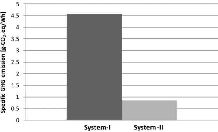
The environmental impact of the systems studied is compared calculating the specific GHG emissions from these systems. It is found that System-I has higher GHG emissions compared to System-II. As shown in Figure 5, the specific GHG emissions from System-I and System-II are 4.564 g-CO2.eq/Wh and 0.847
g-CO2.eq/Wh, respectively. 0 0.5 1 1.5 2 2.5 3 3.5 4 4.5 5 S p e cif ic G H G e m is sio n [ g -CO 2 .e q / W h ] System -II System-I
Fig. 5. Specific GHG emissions of the System-I and System-II
5. CONCLUSIONS
In this paper, the performance and environmental impact of an advanced biomass gasification and SOFC system are compared with a conventional biomass fueled power production system using steam turbine as the electricity generator. A heat transfer model for the SOFC and thermodynamic models for the rest of the components of the systems are used in the analyses. The results of the case study conducted show that the SOFC and biomass gasification system has higher electrical and exergetic efficiencies, and lower specific GHG emissions. This study has pointed out that gasifying the biomass and then using the product gas in SOFC for electricity production is a very efficient way to obtain better performance and lower GHG emissions. As a future study, optimization of the SOFC and biomass gasification system will be carried out to maximize the electrical and exergetic efficiencies and minimize the cost of the system.
Acknowledgment
The financial and technical support of an Ontario Premier’s Research Excellence Award, the Natural Sciences and Engineering Research Council of Canada, EcoEnergy Technology Initiative Program, AAFC-NRC Bioproducts Program, Carleton University and University of Ontario and Institute of Technology is gratefully acknowledged.
REFERENCES
Achenbach, E., 1996, SOFC stack modelling, Final Report of Activity A2, Annex II: Modelling and Evaluation
of Advanced Solid Oxide Fuel Cells, International Energy Agency Programme on R, D&D on Advanced Fuel Cells, Juelich, Germany
Athanasiou, C., Coutelieris, F., Vakouftsi, E., Skoulou, V., Antonakou, E., Marnellos, G., Zabaniotou, A., 2007,
From biomass to electricity through integrated gasification/SOFC system-optimization and energy balance,
International Journal of Hydrogen Energy, 32, pp.337-342
Braun, R.J., 2002, Optimal design and operation of solid oxide fuel cell systems for small-scale stationary applications, PhD thesis, University of Wisconsin-Madison
Colpan, C.O., Hamdullahpur, F., Dincer, I, Yoo, Y., 2009a, Effect of gasification agent on the performance of solid oxide fuel cell and biomass gasification systems, Proceedings of the International Conference on
Hydrogen Production 2009, May 3-6, 2009, Oshawa, Canada, pp. 322-334.
Colpan, C.O., 2009, Thermal modeling of solid oxide fuel cell based biomass gasification systems. PhD
thesis, Carleton University [In Press]
Cordiner, S., Feola, M., Mulone,V., Romanelli, F., 2007, Analysis of a SOFC energy generation system fuelled with biomass reformate, Applied Thermal Engineering, 27, pp. 738-747
Franco, A., Giannini, N., 2005, Perspectives for the use of biomass as fuel in combined cycle power plants,
International Journal of Thermal Sciences, 44, pp.163-177
Mitchell, C.P., Bridgwater, A.V., Stevens, D.J., Toft, A.J., Watters, M.P., 1995, Technoeconomic assessment of biomass to energy, Biomass and Bioenergy, 9, pp.205-226
Omosun, A.O., Bauen, A., Brandon, N.P., Adjiman, C.S., Hart, D., 2004, Modelling system efficiencies and costs of two biomass-fuelled SOFC systems, Journal of Power Sources, 131, pp.96-106
Panopoulos, K.D., Fryda, L.E., Karl, J., Poulou, S., Kakaras, E., 2006a, High temperature solid oxide fuel cell integrated with novel allothermal biomass gasification Part I: Modelling and feasibility study, Journal of
Power Sources, 159, pp.570-585
Panopoulos, K.D., Fryda, L.E., Karl, J., Poulou, S., Kakaras, E., 2006b, High temperature solid oxide fuel cell integrated with novel allothermal biomass gasification Part II: Exergy analysis, Journal of Power Sources,
159, pp.586-594
Pritchard, D., 2002, Biomass Combustion Gas Turbine CHP, ETSU B/U1/00679/00/REP, Talbott’s Heating