OF THE STIRLING CYCLE
by
PEDRO AGUSTIN RIOS Y CARTAYA
B.S.M.E. Massachusetts Institute of Technology (1959)
B.S.I.M. Massachusetts Institute of Technology (1960)
M.S, M.E. Massachusetts Institute of Technology
(1967)
SUBMITTED IN PARTIAL FULFILLMENT OF THE REQUIREMENTS FOR THE
DEGREE OF DOCTOR OF SCIENCE at the MASSACHUSETTS INSTITUTE OF TECHNOLOGY September, 1969 Signature of Author. Certified
--
---. W .W . .*Department 'I Mechanical Engineering, June 4, 1969
by...
.
. . . ... ...Thesis Supervisor
Accepted by... . ... ...
Chairman, Departmental Committee on Graduate Students
Archives
MSS. is- .
AUG
2
9
1969
AN ANALYTICAL AND EXPERIMENTAL INVESTIGATION OF THE STIRLING CYCLE
by
Pedro Agustfn Rfos y Cartaya
Submitted to the Department of Mechanical Engineering on June 4, 1969 in partial fulfillment of the requirement
for the degree of Doctor of Science
ABSTRACT
A model for the calculation of the over-all performance of the Stirling cycle is presented. This model decouples the losses due to adiabatic compression and expansion from the losses due to imperfect components in the system and permits considerable simplification in the analytical treatment,
A cycle with two adiabatic cylinders and a crank-connecting-rod driving mechanism is considered, and the
differential equations are integrated numerically to an over-all steady state. An arbitrary set of volume variations may be used.
Losses due to imperfect heat transfer in the heat-exchange components, losses due to pressure drop, and losses due to the
oscillatory motion of the piston in the longitudinal temper-ature gradient which exists in the cylinder have been treated analytically. Corrections for these losses are then made to the model which has been calculated previously.
A two-cylinder Stirling-cycle refrigerator has been con-structed, and data have been taken for the over-all perform-ance, as well as for the losses which have been examined analytically. The performance yielded by these data may be
successfully predicted by the analytical treatment.
Some of the aspects of the design of a Stirling-cycle refrigerator are discussed.
Thesis Supervisor: Joseph L. Smith, Jr. Title: Professor of Mechanical Engineering
TABLE OF CONTENTS ABSTRACT... . ... . . .. .. .. . .. ... ... ** * * * 2 LIST OF TABLES . . .. . * .* * * * * * * .. . . . * . . .
5
LIST OF FIGURES... 6 ACKNOWLEDGEMENTS... 8 LIST OF SYMBOLS. ....a . . .. . . . .. . . . .. .* . .. * 9 Chapter I INTRODUCTION. ... .. . . * .. . * . . . * *15
H ist or ical.. . . . ... 1 0000000090000*0005
The Ideal StirlingCycle... 16Previous Analytical Work... 19
Objectives.
.. . ... ... ... 22II. THE STIRLING CYCLE WITH PERFECT COMPONENTS... 24
Analytical
Model...
24Relationship to the RealCycle...
31
Experimental
Verification...
33III. LOSSES DUE TO IMPERFECT COMPONENTS IN A REFRIGERATOR... 40
Pressure
Drop...
.41
Analytical Model... 41
Experimental Verification...
44
Imperfect Heat Transfer in the Heat Exchangers....
47
Imperfect Heat Transfer in the Regenerator...
50
Analytical
Model...
50
Experimental Verification...
53
Other
Losses...
...56
IV. CONCLUSIONS AND RECOiENDATIONS... 61
C
onclusions...
... 61Modification of theExperiment... 61
Recommendations for FurtherWork...
63
FIGURES...
... ... ... ... ... ... ... 090 999966REFERENCES... .... ....
0
0 .. ..... . . .* .. * 0 0 * * 000 93BIBLIOGRAPHY... 95
Appendices A. EQUATIONS FOR THE STIRLING CYCLE WITH PERFECT COMPONENTS... 97
B. LOSSES DUE TO PRESSURE DRP... 105
Evaluation of SP ... 107
Evaluation of P d(gyVC)'''''''''''''''''''''''''''' 114 C. REGENERATOR HEATEXCHANGE... 121
D. THE EFFECT OF PISTONMTION... 128
Piston-Cylinder Heat Transfer... 129
Gas Motion in the Radial Clearance... 136
E. DESCRIPTION OF COMPUTERPRGRAM... 139
F. RELATION TO THE ONE-CYLINDER MODEL... 145
The Stirling Cycle with Perfect Components... 145
The Effect of Imperfect Components on the One-Cylinder
Model.
. ... ,... 148 PressureDrop..4...
48 HeatTransfer...
150 G. EXPERIMENTAL APPARATUS... 152 Description of Apparatus... 152 Instrumentation... 155 Experimental P 156 H. DESIGN CONSIDERATIONS FOR A REFRIGERATOR... 159Selection of a Design with Perfect Components... 160
Selection of the Heat-Exchange-Component Design.... 162
Other L s e ... ... .. 166
I. CAlCULATION
EXAMPLE.
. . . .. . ... ... 167Model with PerfectComponents... 167
Losses Due to PressureDrop... 171
Losses Due to Imperfect Heat Transfer... 175 O ther Los s es a...00
0 0 0 0 0
177BIOGRAPHICAL SKETCH...*.*...* .. *..**.* * .e
LIST OF TABLES
Summary of Refrigerator Data...*...*...
Pressure-Drop
Loss...
Summary of Regenerator-Heat Transfer Data..--....-Summary of Data for Losses Due to Piston Motion--.. Summary of Example Calculation...1. 2.
3.
4.5.
3446
55
59
179I
LIST OF FIGURES
1. TwoJ-ylinder StirlingCycle...
66
2. Pressure-Volume Diagram for Ideal Stirling Cycle.. 67 3. Temperature-Entropy Diagram for the Ideal
Stirling Re...
68
4a Experimental Refrigerator (Cold En)... 694b Experimental Refrigerator (Warm End)... 70
5. Dimensionless Cold WorkW, Warm WorkW(
and Pressure Ratio r for rT = 0.62, $D= 2.14,
rcs =
4.8,
Using Helium (Tests Nos. -4)... 716.
Dimensionless Cold WorkW, Warm Workwv andPressure Ratio r for r = 0.92, cD = 2.54,
r = 4.8, Using Helium (Tests Nos. 5-12)... 72
7.
Dimensionless Cold Work' , Warm Workw{a and Pressure Ratio rp for r = 1.87,'VD
= 3.48,ros = 4.8, Using Helium (Tests Nos. 13-20)...
73
8. Dimensionless Pressure Versus Crank Angle for
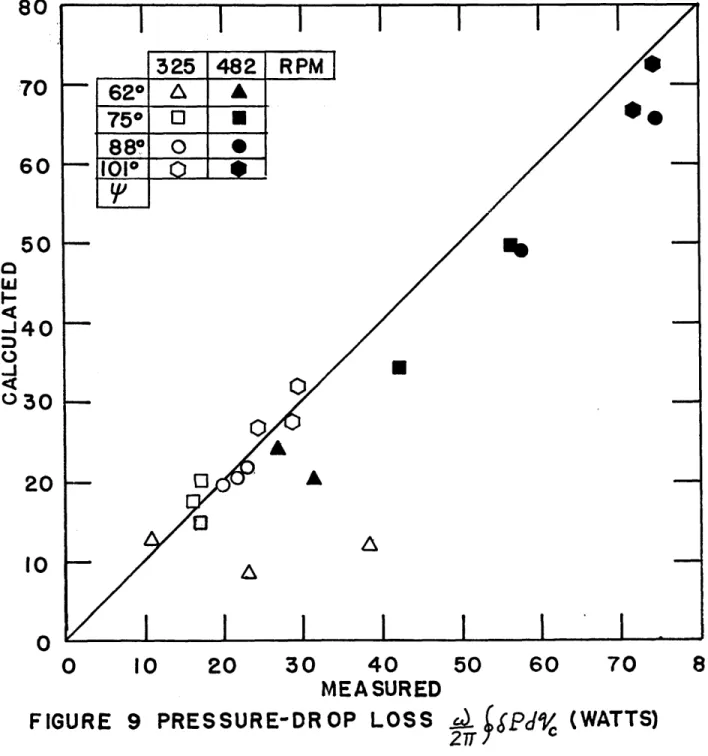
Test Number 15.*.*. ... 74 9. Pressure-Drop Loss J isP dC ... 75 10. Heat-Transfer Correlation for Regenerator...
76
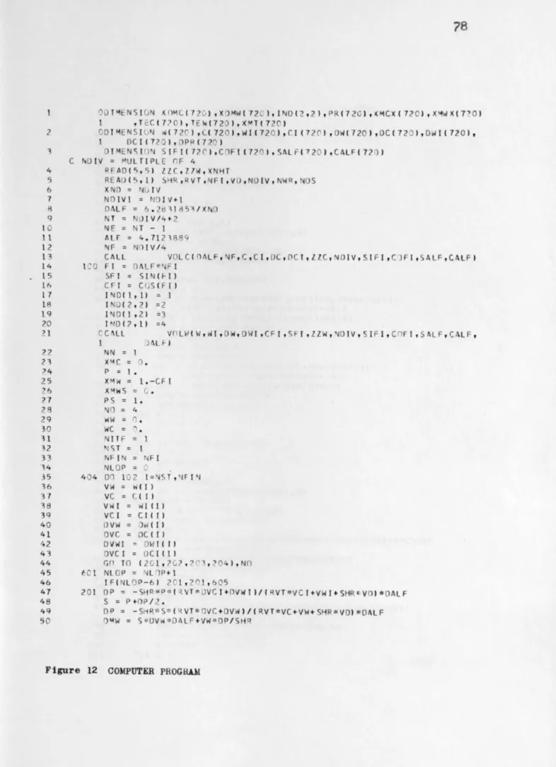
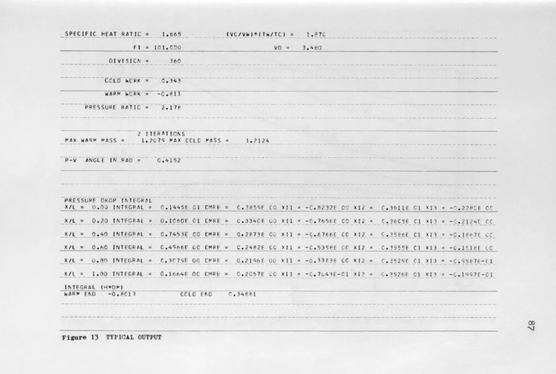
11, Breakdown of Indicated Refrigeration (Tests 29-36) 77 12. Computer Program... ... 7813. Typical 0upt... 87
14. Dimensionless Cold Work for
p
= 900 and ros -48,Using Heim... 88
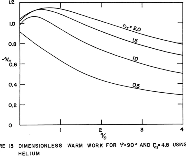
15. Dimensionless Warm Work for = 900 and r0 = 4.8,
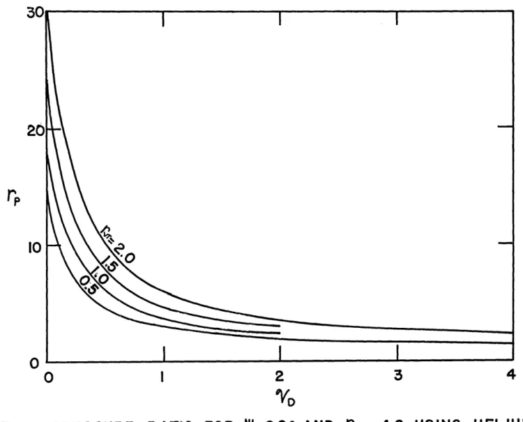
16. Pressure Ratio for P= 900 and rcs = 4.8,
Using Helium... . 00 0 .... 0 .0e.g. . . . . .... .
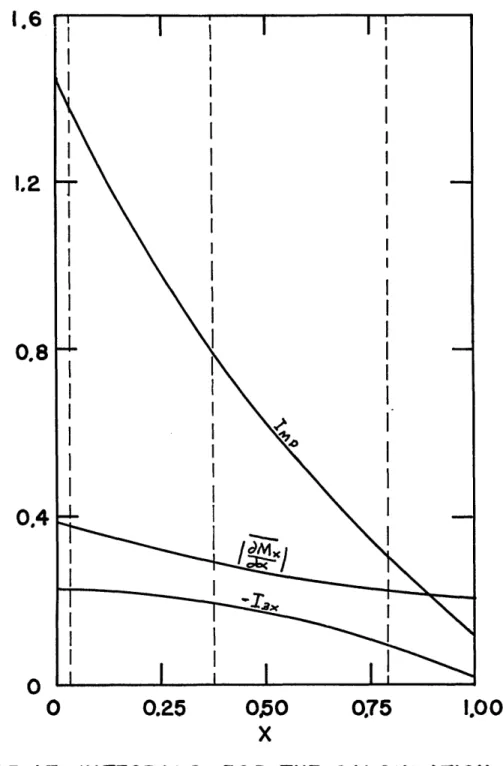
17. Integrals for the Calculation of the Losses for Test No. 15... ... ...
18. Cylinder-Wall-Temperature Distribution...
90
91
ACKNOWLEDGEMENTS
I would like to express my gratitude to the members of my thesis committee, Professors Peter Griffith, David G. Wilson and Joseph L. Smith, Jr. for their suggestions and
guidance in the work which led to this thesis. In par-ticular, Professor Smith was a great source of encourage-ment throughout the time I have spent in the M. I. T. graduate school.
The staff of the M. I. T. Cryogenic Engineering Labo-ratory was always ready to help during the construction of the apparatus' Karl Benner and Jerry O'Callahan lent a helping hand when it was most neededand my fellow students Phil Thullen and Ken Koenig provided lively discussion on many points.
During this time my financial support came from a
research assistanship from the Cryogenic Engineering Labo-. ratory and from a fellowship granted by Air Reduction
Company, for which I am very grateful. Other support, both material and moral, came from my parents and my wife, Thania.
The M. Io T. Computation Center provided the facilities for running the computer programs.
LIST OF SYMBOLS
AFR = Free-flow area AH = Heat-transfer area B(a,b) = Beta function
CH = Coefficient in equation (H-6) Co = Coefficient in equation (H-7)
c p = Specific heat at constant pressure cv = Specific heat at constant volume D = Diameter
d = Hydraulic diameter
dpART = Particle diameter in regenerator matrix E = Energy
f = Friction factor &p/[(L/d)(G2/2))
G = Mass velocity
= Net enthalpy flow per cycle into cold cylinder due to gas flow into the radial clearance
Hpc = Net enthalpy flow per cycle into cold cylinder due to piston-cylinder heat transfer
HR = Net enthalpy flow per cycle along regenerator due to imperfect heat transfer
h = Convective heat-transfer coefficient
hp = Enthalpy per unit length defined by (D-21) hT = Enthalpy per unit mass
hx = Convective heat-transfer coefficient defined by (C-4) Ilx = Integral defined by (C-18)
I2x = Integral defined by (C-19)
13x = IlxI2x
KC = Coefficient in equation (H-9)
k = Specific-heat ratio
k 9 = Thermal conductivity of gas
k = Thermal conductivity of piston p
L = Heat-exchange-component length L = Length of piston
= Piston end clearance r = Piston radial clearance
iC = Dimensionless mass in cold cylinder mCRTC/PAXAC
MlAx =Dimensionless mass amplitude (Mx-jAX - Mx-MIN)/2
M = Dimensionless mass in warm cylinder %RT /pMXVAV M= Dimensionless mass mRTC /pMAXVAC
m = Mass of gas in cylinder m= Mass flow
mA = Mass amplitude (mMAX - mMIN)/2
mA = Mass amplitude (mx-MAX
-mX-Min)/2
nyD = Mass of gas in dead space
DCx = Mass of gas in dead space on the cold side of location x
111DWx = Mass of gas in dead space on the warm side of
location x
= Mass of gas in the piston radial clearance
= Total mass of working gas
= Total mass of gas on the warm side of location x NpH = Pressurization effect defined by equation (C-13) NTU = Number of transfer units
Nu = Nusselt number
P = Dimensionless pressure p/pMAX Pr = Prandtl number
pA = Pressure amplitude (p/2
-p = Mean pressure (pIX +
pMIN)/2
Q = HeatQC = Heat transferred to the gas in the cold exchanger per cycle
Qw = Heat transferred to the gas in the warm exchanger per cycle
q = Rate of heat transfer to piston R = Gas constant
Re = Reynolds number (id)/(AFR1)
rcs = Ratio of the connecting-rod length to one half the stroke r = Pressure ratio p / IIN r p = Pressure ratio pA rVT = Displaced-mass ratio S = Surface area St = Stanton number (hAFR/ic ) s = Stroke
T = Temperature of gas in cylinder T
=
Heat-exchanger-wall temperatureTAc = Cylinder-surface-temperature-variation amplitude defined by (D-1)
TAp = Piston-surface-temperature-variation amplitude T C = Cylinder-surface temperature
T = Piston-surface temperature T, s = Piston-seal temperature
T= Gas temperature at location x
t =Time
V = Cylinder volume
VA = Cylinder-volume amplitude (VMA - MIN)/2
V D = Heat-exchange component dead volume VG = Volume of piston radial clearance
Vx = Dead volume on the cold side of location x
OV = Dimensionless cylinder volume V/VA
D = Reduced dead volume
= Cold-exchanger reduced dead volume YDR = Regenerator reduced dead volume VDW = Warm-exchanger reduced dead volume
IV = Work done by the gas in a cylinder per cycle = Dimensionless work per cycle W/pMUVA
X = Parameter defined by equation (B-29)
X, k' = Position
GREEK SYMBOLS
Of = Crank angle
arp = Thermal diffusivity of piston
Mc = Thermal diffusivity of cylinder wall # OJ(9 = Parameters defined by equation (D-20)
Ofx = Phase angle of mass flow with respect to pressure A T = Temperature span (T,7' - TC
0
Sp= Instantaneous pressure drop in the heat-exchange components
&QCp = Refrigerative-power loss due to pressure drop in the cold exchanger
6QRp = Refrigerative-power loss due to pressure drop in
the regenerator
6~gg = Refrigerative-power loss due to pressure drop in
the warm exchanger
T
Tc = Temperature fluctuation at a point on the cylinder-wall surface
JT = Temperature fluctuation at a point on the piston
surface
e
= Dimensionless temperatureA, = Heat-transfer parameter defined by equation (D-31)
= Regenerator ineffectiveness defined by equation (C-15)
4 = Viscosity
= Porosity
= Phase angle of the pressure with respect to the cylin-der-volume variation
= Phase angle of the mass with respect to the cylinder volume variation in the radial clearance
= Phase angle of the mass with respect to the pressure variation in a cylinder
4
= Phase angle of the cylinder volume with respect to the pressure variation= Dimensionless position x/L
= Volume phase angle
= Circular frequency 2/period
SUBSCRIPTS
AVG = Average value
C = Cold cylinder; cold exchanger; evaluated at T5 CR = Evaluated at the cold end of the regenerator MAX = Maximum value
W = Warm cylinder; warm exchanger; evaluated at T A WR = Evaluated at the warm end of the regenerator
CHAPTER I
INTRODUCTION
Historical
The Stirling engine was invented early in the nineteenth century by Robert Stirling. This engine originally used hot air as a working fluid and was, therefore, called a hot-air engine. It enjoyed some degree of success as a prime mover for low-power applications for a number of years. Although a number of modifications were made to the original cycle, the lack of understanding of regeneration and of how the regenerator affected the performance of the cycle prevented the Stirling engine from competing with the steam engine and the internal-combustion engine. Therefore, the Stirling engine disappeared from practical use.
Research on the Stirling cycle was started again at the Philips Research Laboratories in Holland in 1938. This
research was directed towards the design of a small power source for radios and other electronic equipment. It was thought that the use of new techniques and materials could make the Stirling engine practical again.
A refrigerator operating on the reversed cycle was also investigated. This has resulted in the commercial production
of an air liquefier since 1955. Refrigerators for lower
temperatures have also been built. An excellent historical
(3)
review of the Stirling engine has been made by Finkelstein .
by Philips.
The Stirling engine is an external-combustion engine, and, therefore, the combustion of the fuel is not limited by the factors which prevent complete combustion in the internal-combustion engine. Where air pollution is important, the
external-combustion engine compares favorably to the internal-combustion engine. This has led to a re-examination of the Stirling engine, as well as the steam engine, for use as an automotive engine.
On the other hand, the cycle's simplicity and compactness makes it look very attractive for some compact low-temperature refrigeration applications.
The Ideal Stirling Cycle
Stirling-cycle machines have been built in various
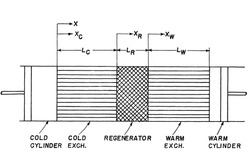
configurations, but in general the cycle may be characterized by two variable volumes with adjacent heat exchangers through which the gas enters and leaves. The two heat exchangers are at different temperatures. The heating and cooling of the gas as it moves from one heat exchanger to the other is achieved by means of a thermal regenerator.
One configuration which fits this description is shown in figure 1. Here, the variable volumes consist of piston-cylinder assemblies. This is the configuration which will be used for analytical purposes because the piston displace-ment may always be made such as to simulate the volume
Consider now the ideal model of the Stirling cycle. In this idealized model both the warm cylinder and the cold cylinder are considered to be isothermal and at the temper-ature of the adjacent heat exchanger. The heat-exchange components are considered to be perfect (no pressure drop, no axial conduction, and no temperature difference between
the working gas and the heat-exchanger surface), and to have zero dead volume.
To illustrate how the ideal cycle operates, consider initially that the warm piston is at bottom dead center, while the cold piston is at top dead center.
Process 1-2: The warm piston is moved to reduce the volume which is available to the working gas in the warm cylinder. An isothermal compression at the warm temperature takes place.
Process 2-3: When the maximum desired pressure is reached, the warm and cold pistons are moved simultaneously so that the total volume is constant until the warm piston reaches top dead center and all the gas is at the cold temper-ature. This process is a constant-volume cooling.
Process 3-4: The cold piston is now moved to bottom dead center while the warm piston is held at top dead center and the gas is expanded isothermally at the cold temperature.
Process 4-1: Both pistons are moved while maintaining a constant total volume until the warm piston is at bottom dead center and the cold piston is at top dead center. This may be represented by a constant-volume heating.
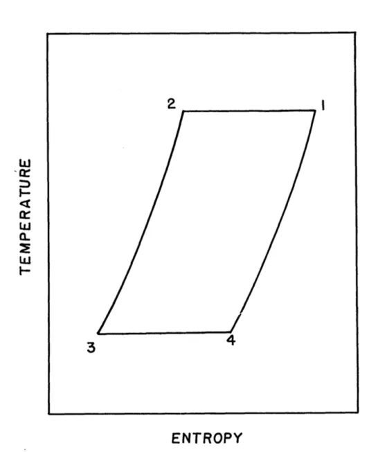
The cycle which as been described consists of two isothermal volume changes and two isometric heat exchanges which are performed reversibly. They may be represented in the pressure-volume and temperature-entropy diagrams as
shown in figures 2 and 3. It is clear from these diagrams that net refrigeration has been produced at the cold temper-ature. If the piston motion is reversed, the cycle will be reversed and net work will be obtained. Since all the
processes are reversible, the efficiency of the process is equal to that of a Carnot cycle.
It is clear that the cycle which has been described
above must be performed infinitely slowly in order to achieve isothermal volume changes. On the other hand, all of the real heat-exchange components contain a mass of gas, the mass being a function of pressure and temperature. Therefore, the volume of the heat-exchange components affects the pressure ratio. Also, the piston motion which has been described is impractical, since it would require a complicated mechanism.
A practical Stirling cycle which is operated at a reasonable speed will behave very differently from the
idealized cycle which has just been considered. In fact, the cylinders of a practical machine are nearly adiabatic instead of isothermal, the fraction of the total working gas contained in the heat-exchange components may be greater than one half, and the losses associated with heat exchange and pressure drop are quite significant.
Previous Analytical Work
The analysis of the Stirling cycle is made difficult by the fact that the heat-exchange components affect the over-all performance not only through pressure-drop and heat-transfer effectiveness, but also through the volume contained by these components. This volume, which is occupied by the gas, must be pressurized and depressurized each cycle at the same time that gas moves in and out of the variable volumes.
Since the volume in the heat exchangers (dead space) is a significant portion of the total volume in a machine, an important fraction of the working fluid is utilized to pressurize this space instead of being actually moved from one variable volume to another to effectively contribute to the net work or refrigeration. Therefore, a significant amount of work must be expended in order to pressurize the dead space. Ideally, this work is recovered when the dead space is depressurized.
A heat transfer due to the heat of compression is
associated with this work. A heat transfer oppositie to the previous one is associated with depressurization, so that if these processes take place without irreversibility, then both effects will cancel out.
However, in a practical cycle the cylinders are nearly adiabatic, and an irreversibility does exist when gas moves from a cylinder into the adjacent heat exchanger at a temper-ature different from the heat-exchanger wall tempertemper-ature. In fact, the losses due to this irreversibility can be very
significant.
The heat-exchange-component design affects the pressure ratio and the mass of gas which must circulate from the
cylinders, and therefore is intimately related to the
irreversibility in the cycle. This irreversibility exists even when the heat exchange is perfect and pressure drop is neglected. The close dependence of the overall performance of the cycle on the heat-exchange-component design makes the analysis more difficult than that of a steady cycle. Since mass is stored in the dead space, the equation for conserva-tion of mass becomes more complex, and it must be satisfied by mass flows which vary in space and time.
Early analyses of the Stirling cycle avoided this problem by simply considering reversible processes and heat-exchange components with no internal volume, essentially as described for the ideal cycle. It was Schmidt (21)who first considered the effect of dead volume in what is considered the classical analysis of the cycle. However, since he considered reversi-ble processes only, the efficiency yielded by the Schmidt
analysis is still equal to the Carnot efficiency.
More recent analyses(6-9, 11-13, 23-25)have attempted to consider the effect of irreversibilities on the overall
performance of the cycle. Generally, the approach which has been taken is to write the differential equations for the
irreversibilities as well as for the overall cycle and to solve these equations simultaneously. The coupling between the Stirling-cycle equations and the equations for pressure
drop, heat-exchanger temperature differences, regenerator performance, etc, requires the simultaneous solution of a large number of partial-differential equations which are mostly non-linear. Because of this complexity, solutions have been obtained for a limited number of special cases where important losses are neglected.
A different approach to the problem has been taken by
Qvale and Smith(1 7 . In this analysis, the effect of pressure drop and heat-transfer effectiveness on the overall cycle
performance has been decoupled from the effect of the dead
space. This decoupling permits the calculation of the
perform-ance of a basic model which does not include irreversibilities
in the dead space, and the modification of the overall
perform-ance to include these irreversibilities at a later stage.
This considerably simplifies the calculation of the overall
performance of a cycle, and permits the use of models of
various degrees of sophistication for the individual
compo-nents.
In order to solve the differential equations for the
basic model, a shape for the time variations of the mass flow, the pressure, and variable volumes was assumed. All these
variations were assumed to be sinusoids. This means that
when the phase angle between the mass and the pressure
sinus-oids, the pressure ratio, and the gas properties are fixed, then the volume variation and the work for that particular
cylinder may be found.
the pressure be sinusoids in order to simply interrelate two cylinders, which have been calculated separately (one for the warm end and one for the cold end), by means of the equation
for the conservation of mass for the overall model. The mass in the dead space is proportional to pressure. If the pres-sure is a sinusoid and the mass flowing in and out of the dead space is a sum of two sinusoids (one for the flow from
each cylinder), then conservation of mass in the dead space determines a simple relationship between the amplitudes and phase angles of the sinusoids representing the mass in each cylinder.
The assumption of sinusoidal pressure and mass variations imposes some constraints on this analysis. The shape of the volume variation resulting from sinusoidal pressure and mass variations is dependent on the relative magnitude and pahse angles of the mass and pressure. In other words, the shape of the volume variation cannot be specified and the effect of varying this shape cannot be ascertained. As the pressure ratio of a Stirling cycle is increased, both the mass and the pressure will tend to deviate increasingly from sinusoidal
shapes. The errors introduced by assuming sinusoids are not known, since few detailed data have been published on Stirling-cycle performance.
Objectives
It is the purpose of this thesis to present and evaluate an analysis which will be of more general application to the
Stirling cycle and its variations than are the existing
analyses. In order for the analysis to be useful for design purposes, where a large number of alternatives must be compared, it must not require extensive computation. Therefore, the
decoupling of the heat-transfer and pressure-drop losses achieved in the one-cylinder model will be preserved.
The data necessary to confirm the analytical results are to be obtained and presented.
This thesis will concentrate on the treatment of a refrig-erator, but the analytical results are just as applicable to an engine. The over-all steady-state performance of a Stirling cycle with adiabatic cylinders will be derived by first
con-sidering a refrigerator with perfect components. This means that in the first approximation the only irreversibilities are due to adiabatic expansion and compression. This is treated in Chapter II. Chapter III then deals with the corrections necessary to include the principal
irreversi-bilities found in the real cycle. These losses include imper-fect heat exchange, pressure drop, and heat transfer from the environment through various mechanisms.
CHAPTER II
THE STIRLING CYCLE WITH PERFECT COMPONENTS
As a first approximation to the Stirling cycle, consider a system with perfect components as shown in figure 1. By perfect it is meant that there is no pressure drop and no gas-to-wall temperature difference in the heat-exchange components, no axial conduction nor heat transfer from the environment, and no irreversibility due to friction in the cylinders. It is also considered that the cylinders are perfectly adiabatic.
Analytical Model
The differential equations governing the behavior of the Stirling cycle with perfect components are derived in Appendix A. The assumptions made in this derivation are as follows:
1. The cylinders are adiabatic. In the early analyses of the Stirling cycle the cylinders were considered to be isothermal. This was due more to the ease of analyzing a constant-temperature cylinder than to the existence of
iso-thermal conditions even in the slow machines of the nineteenth century. Stirling-cycle machines which have been designed recently operate at relatively high speeds. This makes the heat transferred per cycle in a cylinder negligible when compared to the work transfer per cycle. Attempts have been made to obtain isothermal compression by increasing the piston and cylinder areas, but up to the present time they have not
been of practical importance.
2. Perfect heat-exchange components. This assumption is made for the first approximation only and will be removed by subsequent corrections.
3. The gas density at any point in a heat-exchange
component is a function of pressure only, and, therefore, the mass of gas in a component is a function of pressure only. Since the working gas is exchanging heat with a
constant-temperature medium in the heat exchangers, it follows that for efficient heat exchangers the variation in the temperature of the gas in the heat exchanger must be small when compared to the absolute temperature. Therefore, the mass contained in a heat exchanger may be considered to vary with pressure only.
In the regenerator, the gas is exchanging heat with a solid matrix material. It is generally true that the heat capacity of the solid matrix is higher by several orders of magnitude than the heat capacity of the gas which moves into and out of the regenerator during one cycle. For a relatively efficient regenerator the temperature variation at a point must therefore be small when compared to the absolute temper-ature, and the mass in the regenerator may be considered to vary with pressure only.
There are exceptions to this, such as when the regener-ator is operating at very low temperature and the specific heat of the matrix becomes a function of temperature(20 ) but in general they will exist only in special applications.
perpendicular to the direction of flow; therefore, the problem may be treated as one dimensional in space.
5. The gas in each cylinder is perfectly mixed. The amount of mixing in the cylinder will depend on the way in which the gas enters the cylinder from the heat exchanger. Generally, the free flow area of the heat exchanger will be
less than that of the cylinder, and there will be relatively effective mixing when the jet of gas enters from the heat exchanger into the slower-moving gas in the cylinder. The assumption of perfect mixing is a good approximation in most practical cases.
6. The working gas is a perfect gas. Previous work on the Stirling cycle has shown that helium and hydrogen are the best gases to use as a working gas because of their heat-transfer and viscous properties. These two gases will behave as perfect gases to approximately 100K in the case of helium and 600K in the case of hydrogen.
With these assumptions, the mass contained in the dead space may be said to vary only with pressure, and the effect of the dead space on overall performance may be lumped so that
in effect the perfect heat-exchange components are represented by a single lumped parameter.
The differential equations for pressure, mass, and work are derived in Appendix A. There are four sets of equations because each cylinder obeys a different equation when gas is moving in or out of it, so that four combinations may be formed with two cylinders. In order to determine which
equation applies at a given time it becomes necessary to keep track of the mass flow at all times.
The equations have been derived in terms of the following dimensionless parameters. The basic geometry parameters are
(2-1)
and VAW
W -(2-2)
These parameters are both mass ratios. The reduced dead volumeVD is the ratio of the mass mD contained in the dead space at pressure p, to the mass contained in one half the warm-cylinder displacement volume VAW at the warm-exchanger
temperature T and the same pressure p. The second parameter, rVT, or displaced mass ratio, is the ratio of the mass contained in one half the cold-cylinder displacement volume VAC at the cold-heat-exchanger temperature T* to the corresponding
C
quantity for the warm cylinder.
The variable cylinder volumes V0 and V, may be expressed as
95-
V/V
(2-3)and
y W / A AW (2-4)
for the cold and warm cylinders respectively.
The mass in a cylinder, n or mn, may be expressed in terms of the mass contained in one half the corresponding cylinder displacement at the maximum cycle pressure p and the temperature of the adjacent heat exchanger. This leads to
C= ,, / (2-5) for the cold cylinder, and
(2.6) for the warm cylinder.
The pressure may be expressed as the fraction of the maximum pressure
.P-~ (2..7)
In terms of these variables the differential equations for the pressure may be written:
012 - vr ICY 0 Vw A 14
4
YD (2..8) when 0'o WAW 0.r7 C *'M 7V
a'i-
r Mct.Mw4 '
P P (2-9)
when Af <0, dAf<O.
CV-6 V 7 VT C 9-C- ( 2-10
when /AlM. -Oa w>0o.
!rr ', -%
Mw
+4"DAO(2-11) when d/C
;P
o,
cO4W
,aMv
=
OY e /c & P (2-12) when /Afg 7'c - -4 Ic ( 2-13)
when &4C <o,
//= VA
}
rd
2
(
2-1L)
when
dAtw?7o
ed'/ A
=
(
(2-15)when 21/ / o.
The dimensionless works V. and may be evaluated from
'
=(2-16)
W W V 0V - 4,4C i - W 9 0WOO(
2- 17) These equations are valid for any arbitrary set of
volume variations. Although the model with perfect components is not time dependent, the heat-transfer and pressure-drop losses which will be calculated later are time dependent, and it is useful to express the volume variations as a function of time. Once the shape of the volume variations is selected, as a function of time, the relative position in time of one volume variation with respect to the other may be expressed in terms of a pseudo-phase angle
//.
This angle may be defined as the time lag between the cold piston and warm pistonThe performance of the Stirling cycle with perfect components may be characterized by the specific-heat ratio
of the working gas, the shape of the cylinder-displacement profiles, displaced mass ratio, a phase angle, and a reduced dead volume.
Solutions to these equations for volume variations given by crank-connecting-rod mechanisms and zero clearance volume have been obtained by the computer program in Appendix E.
The details of the solution are explained in this appendix and only its limitations will be discussed here.
In brief, the solution to the differential equations is carried out by selecting an initial condition for the complete system and emulating the system through its transient behavior until an over-all steady state is reached. The question is
how to accelerate this convergence and what are the limitations imposed by the method. These limitations are on the type of volume variation which may be used.
The solution of these equations has been set up to utilize the fact that when a piston is at its top dead center position the mass in the corresponding cylinder is zero. This provides knowledge of the mass at one point in the cycle for each
cylinder. Any error in the mass computation may be corrected at this point. In addition, the lack of gas in the cylinder at one point in the cycle accelerates the convergence to the over-all steady state. Since the temperature of the incoming gas is fixed by the heat exchanger, the temperature and there-fore the mass in the cylinder will vary from one cycle to the
next only with corresponding changes in the pressure profile. Since the mass in the cylinder goes to zero at one point, the error in the estimate of the initial temperature of the gas in the cylinder is not carried over to the next cycle directly (as it would be if the residual gas in the cylinder mixed with the incoming gas), but instead, its effect is
carried over by perturbing the pressure profile. In addition, since an important fraction of the working gas is in the dead space, which has a fixed temperature, the effect of the initial temperature of the gas in the cylinder on the pressure is
ironed out quickly.
Thus, it has been found that the change in the pressure between the end of the first cycle and the end of the second cycle is usually less then 0.lo.
The computer program may be easily modified to include volume variations which do not go to zero. However, the clearance volume in a cylinder will usually be small, and the error introduced by including this volume as part of the adjacent heat exchanger is not significant. Therefore, this limitation does not seriously detract from the generality of the solution.
Relationship to the Real Cycle
It is necessary now to relate the cycle with perfect components to the real cycle. The gross performance of a cycle will depend on the pressure-volume relationship. In the case of a refrigerator, the refrigeration which is
available per cycle is p dV evaluated at the cold end.
This is true regardless of the pressure-drop characteristics of the heat-exchange components. The net refrigeration which
is produced is this quantity minus the heat loads imposed by axial conduction, imperfect heat transfer, etc. In essence, there are two types of losses; those which affect the cycle performance by modifying the pressure-volume relationship, and those which appear as a heat load on the heat exchangers. The variations due to the first kind of loss must be looked
at in order to relate the model with perfect components to the real cycle.
It may be specified that the pressure-volume relationship of the warm cylinder will remain unchanged regardless of
pressure differences. This may be easily achieved, since both the total mass of working gas in the system and the cold
cylinder volume variation may be changed to achieve this. This means that the warm end pressure p has been defined by
the model with perfect components as
(2-18) while the cold end pressure PC will be a function of p and
the pressure drop characteristics of the heat exchange compo-nents.
(2-19)
It is clear that when the warm end pressure pI is measured for a working cycle, the relationship between the model with perfect components and the real cycle will be
P
((M2...20)4 ( 2..21)
Therefore, in the absence of pressure differences the work at the cold end would have been
i= /(2.22)
ff,
=
Experimental Verification
A series of tests were run on the experimental refriger. ator which is described in Appendix G. The integrals (2-21) and (2...22) and the pressure ratio (2-20) were taken from
indicator diagrams for these tests. The results are tabulated in table 1 and plotted in figures 5, 6 and 7.
The experimental runs were made at three temperature ratios with the cold end temperature ranging from -3154F to
-150F and two speeds which are approximately 480 RPM and 325 RPM.
Because of the difficulty in always achieving equilibrium between the refrigeration output and the heat load at the
same temperature, there are slight differences in the temper-ature ratios of points which are plotted on the same curve, but these differences are negligible. Differences in the phase-angle measurements at different speeds may be largely attributed to a slight stretching of the timing belt
TABLE 1
SUIhIARY OF REFRIGERATOR DATA
Test TC Tw
4)
Vapor Speed Refrig.No. (RPM) Load
(OF) (OF) (0) (Watts)
1 - 14.5 42.0 62.0 Freon 12 326 91.0 2 - 6.0 41.5 89.5 Freon 12 326 111.6
3
- 11.0 42.0 102.0 Freon 12 326 98.0 4 - 12.5 41.0 76.0 Freon 12 326 86.0 5 -163.3 38.5 75.0 Freon 13 325 86.6 6 -163.3 37.5 88.5 Freon 13 325 93.0 7 -167.3 38.5 101.5 Freon 13 325 101.5 8 -162.0 38.5 62.0 Freon 13 325 76.0 9 -162.0 38.5 61.0 Freon 13 483 93.6 10 -164.7 37.5 74.0 Freon 13 483 120.0 11 -164.0 37.5 87.5 Freon 13 483 125.0 12 -164.0 37.5 101.0 Freon 13 483 108.0 13 -317.2 38.3 87.0 Nitrogen 480 48.5 14 -315.4 38.3 73.5 Nitrogen 480 44.o 15 -314.2 38.3 101.0 Nitrogen 481 0.0 16 -311.6 36.3 61.5 Nitrogen 485 17 -313.0 36.0 87.5 Nitrogen 325 29.5 18 -316.2 37.0 101.0 Nitrogen 325 0.0 19 -316.8 38.3 75.0 Nitrogen 325 0.0 20 -311.2 38.3 62.0 Nitrogen 325 0.0TABLE 1 (continued)
No. 2- c W PMAX MIN rp
(Watts) (psia) (psia)
1 11.1 0.521 0.432 176.4 73.6 2.41 2 20.0 0.601 0.496 177.1 91.8 1.93 3 24.4 0.637 0.525 160.6 83.7 1.92 4, 15.7 o.571 o.486 165.9 75.8 2.18 5 17.0 0.441 0.625 289.1 124.1 2.33 6 21.8 0.480 0.667 262.1 123.8 2.12 7 28.6 0.496 o.641 257.6 131.5 1.95 8 22.9 0.388 0.580 279.9 117.2 2.38 9 31.4 0.377 0.589 228.0 87.5 2.61 10 42.0 0.439 0.638 242.7 100.0 2.43 11 57.6 0.499 0.681 226.4 103.5 2.18 12 72.2 0.519
o.619
220.9 108.7 2.04 13 74.6 0.325 0.806 313.0 131.7 2.38 14 56.4 0.299 0.750 321.7 125.3 2.56 15 76.9 0.366 0.827 224.2 96.5 2.33 16 26.5 0.279 0.710 169.8 62.o 2.74 17 23.4 00320 0.722 301.0 133.3 2.26 18 29.14 0.336 0.799 269.9 125.8 2.14 19 17.2 0.286 0.760 298.6 122.0 2.45 0.280 0.672 308.7 20 38.6 120.5 2.56NOTES TO TABLE 1
Static Heat Leak at 1 ATM: 39
Static heat leak at 2.0 torr: * Venting nitrogen vapor from
watts
25 watts
From table 1 it may be seen that by changing the cold end temperature the resulting configurations in terms of r andV are very different for all three temperatures. There-D
fore, the tests may be made to cover a large span in terms of the model with perfect components without actually changing the components.
The data for the pressure ratio rp shows that the pres-sure-ratio estimates from the analysis are relatively close. Both figures 6 and 7 show higher pressure ratios at the
higher speeds than at the lower speeds. The cold exchanger effectively isolates the cold cylinder from the warm cylinder end of the machine. However, heat is leaked into the cold volume from the cold-end crank case by the motion of the piston back and forth along the longitudinal temperature gradient in the cylinder.
Measurements of this heat transfer for a cold-end temper-ature of -320OF indicate that at this tempertemper-ature level the heat input to the cold cylinder is of the order of one half of the indicated refrigeration. Since the pressure reaches its lowest point at nearly the same time that the cold piston is at bottom dead center, it is clear that most of the heat input to the gas in the cylinder will be at the low pressure and decrease the pressure ratio. The refrigeration loss due to the piston motion is relatively insensitive to the speed of the refrigerator, so that its effect will decrease as the speed is increased.
in figure 8 for the case corresponding to test number 15 in table 1. The two curves on this figure show the predicted and experimental values for %/p . It can be seen how the heat transfer to the gas in the cold cylinder when the cold piston is near its bottom dead center position is
sufficient to raise the pressure back to the predicted value early in the compression stroke.
Since the heat transferred into the cylinder is propor-tional to the temperature gradient in the cylinder, it may be expected that figure 6 will show higher pressure ratios than
figure 7.
As the cold end temperature of the refrigerator is raised, the displaced mass ratio rvT decreases. The mass flow at the cold end is about twice as much as that for the warm end when the cold-end temperature is at -3100F. When
-150F is reached the situation is reversed, and the major mass flow shifts to the warm end. This means that the mechanism for pressurization and depressurization of the dead volume must shift from the cold end to the warm end. This is why the trend of higher pressure ratios at smaller
temperature gradients at the cold cylinder is broken.
The data for and show good agreement with the theory. There is a consistent error in the predicted values which shifts as the configuration of the refrigerator is
changed by altering the temperature ratio. The effect of
speed on the work quantities is less than on the pressure
of'/ and are reversed as the temperature ratio varies. In all the calculations for the model with perfect components it has been assumed for the calculation of the reduced dead volume that the porosity of the regenerator was 0.39, and that the gas in the dead space was at T C in theit cold exchanger, TV in the warm exchanger and the mean between TC* and T * in the regenerator.
C W
The accuracy of these assumptions was tested by removing the cold cylinder and blanking off the cold exchanger, and then measuring the ratio of the pressure when the warm piston is at top dead center to the pressure when it is moved slowly to bottom dead center.
Since the mass of gas in the warm cylinder at the bottom dead center position is
2. ?44P I 4w
cyR 7-yA_ (2..23)
the definition of the reduced dead volume (2-1) requires that
=2
Tev./727
- /
(2-24) Equation (2.24) yielded a value for the reduced dead
volume which was 0.6o lower than the calculated value when the pressures were measured with the cold exchanger immersed in liquid nitrogen.
CHAPTER III
LOSSES DUE TO IMPERFECT COMPONENTS IN A REFRIGERATOR
It has been said in Chapter II that the losses due to imperfect components may be divided into two types: those which affect the pressure-volume relationship in the cylin-ders, and those which appear as a heat load on the heat exchangers.
Pressure drop and imperfect heat transfer in the heat exchangers may be included in the first group, while axial conduction, imperfect heat transfer in the regenerator and the effect of piston motion may be included in the second group.
For a refrigerator with perfect components the work per cycle done by the gas at the cold end is equal to the refriger-ation per cycle. This can be easily seen by considering the cold exchanger and the adiabatic cylinder as a system. Since for perfect regenerator and cold exchanger the net enthalpy flow per cycle to the regenerator must be zero for a perfect gas, then for a cycle the heat transferred to the system must equal the work done by the gas in the cylinder.
In order to calculate the refrigeration for a real cycle, the pressure variation at the cold end must be corrected to obtain the indicated refrigeration, and then the heat load imposed by other imperfections must be substracted out to obtain the net refrigeration.
Pressure Drop.
Analytical Model
By definition, the pressure and volume variations at the warm end have been selected such that the model with perfect
components will yield
(2.20) and the pressure at the cold cylinder is given by
& ~ 7 J"R (2-21)
The work per cycle done by the gas at the cold end is given by
It should be made clear that the sign of the term fcp dVC may be positive or negative, so that the refrigeration with pressure drop may be greater than that without pressure drop. This, in fact, will occur at relatively small phase angles for pressure drop introduced near the warm end.
In addition to an increase in refrigeration, an increase in the work done by the gas in the cold cylinder also means a decrease in the net work necessary to produce the refriger-ation; therefore, the refrigeration and the coefficient of performance increase together.
The reason for this unusual behavior is that when pressure drop is introduced and the pressure and volume variations at the warm end are defined not to change because of the pressure drop, then the equation of conservation of mass in the system cannot be satisfied unless the shape of the cold volume vari-ation is also changed.
What this means in terms of a model with perfect compo-nents is that the work at the cold end will be given by
W
fP) cVc)
(3-2)which for small losses may be written as
Cf
Cf'(S
)
(3-3)
It will be assumed that when the pressure drop is small compared to the total pressure, the volume correction term will also be small. Therefore, the order in which the two
correction terms are calculated is immaterial.
Since the order is immaterial, the following procedure may be followed in principle.
1. Select a volume variation for the warm cylinder. This variation will be the same for the idealized model as well as for the real system.
2. Select a volume variation for the cold cylinder of the real system.
3. Determine what the correction SVC is in order to find the equivalent idealized system.
4. Substract the correction SVC from the cold-cylinder-volume variation for the real system and calculate the
per-formance of the model with perfect components.
5. Calculate the correction 1, d(6SV) and correct the performance given by the model with perfect components.
6. Calculate the correction fgp dVC and correct the performance obtained from step (5).
performance given by step (5) may be calculated directly by assuming perfect components and using the real volume varia-tions. In effect steps (2) through (5) calculate, add and substract what amounts to p d(6VC) plus some third order terms.
Therefore, we are justified in calculating the perform.-ance of the model with perfect components directly with the real volume variations and comparing the results to experi-mental values. The correction term due to the volume change
is important conceptually, but it is not necessary in order to calculate the performance of a cycle. It becomes particu-larly important when it is found that an increase in pressure drop will apparently improve the performance of the cycle. When this fact is considered by itself it appears as if it were violation of the second law of thermodynamics.
The evaluation of both correction terms is discussed in Appendix B. The pressure correction term for a heat-exchange component i is shown to be
PRRr-/C
0 (3-4)
The evaluation of the cyclic integral is carried out in the computer program for the idealized model. It may be
and when the final geometry is determined, the longitudinal integration may be carried out. As is shown in Appendix B, the use of mass coordinates instead of length coordinates allows the calculation of the mass integrals at any point in
the system without any detailed knowledge of the heat-exchange component geometry.
If the coordinate X is used to denote the fraction of the reduced dead volume on the cold side of a point x, then
it can be shown that
d~
c
')A4u)
Mcd o( r ol / C)C (3-5)
Once detailed knowledge of the heat exchangers is
available, then the variable may be converted back to lengths for the calculation of pressure drops by the relations:
'(K'
*2/c
(3-6)
for the cold exchanger,
- /
-/
e- P(3-?)
for the regenerator, when the temperature distribution is linear with respect to position, and
(3-8)
for the warm exchanger.
Experimental Verification
Data on the over-all evaluation of Ic-p dVC for the heat-exchange components was obtained simultaneously with the data
for the idealized model. The integrated experimental values are shown in table 2 together with the calculated values.
The calculation of the predicted values for JSP d75 was done by using the values of the cyclic integral in (3-4) computed at five equally spaced location in terms of X by the computer program for the model with perfect components.
The values for these five points were plotted versus X and the values of X corresponding to the interfaces between
the heat exchangers and the regenerator were marked.
The space integration of the pressure drop in the heat exchangers was carried out by simply assuming that the friction factor and the cyclic integral are both constant with position in the heat exchangers, and that their value is given by the value at the center in terms of X. The pressure drop for the regenerator was calculated for the conditions at the ends and at the center position in terms of X, and Simpson's rule was used to obtain an average value.
Although the variation of gas properties with temperature along the longitudinal axis was accounted for, the Reynolds number and the friction factor were evaluated at time-averaged absolute values.
The regenerator matrix was assumed to be composed of
randomly packed spheres. The data given by Kayes and London( 10) was used to evaluate the friction factor.
Figure 9 shows the experimental data plotted against the predicted values for the pressure drop correction. The data shows good agreement with the predictions.
TABLE 2
PRESSURE DROP LOSS
---- V (watts)
Zrr7
CALCULATED
Test Cold Warm
No. Exchanger Exchanger Regenerator Over-all
1 2
3
4
5
6
7 89
10 11 12 13 14 1516
17 1819
20 2.2 2.6 2.6 2.4 1.7 1.9 1.9 1.7 3.7 3.8 4.1 4.3 7.8 7.2 6.9 4.1 2.6 2.7 2.14 2.1 -1.8 2.2 5.2 0.0o.4
2.7 5.0 -1.7 -3.7 0.8 5.9 11.1 9.2 4.1 13*7 -1.0 4.1 6.3 1.9 -0.5 12.414.6
19.0 10.3 12.4 16.1 20.6 8.4 20.5 29.8 39.251.4
48.6 38.5 52.8 20.8 15.2 23.015.7
10.1 12.8 19.3 26.8 17.714.5
20.7 27.5 8.4 20.534.14
49.266.8
65.6
49.873.14
23.9 21.9 32.0 20.0 11.7 MEASURED Over-all 11.1 20.0 24.4 15.? 17.0 21.8 28.6 22.9 31.4 42.057.6
72.274.6
56.4
76.9
26.5
23.4 29.4 17.238.6
It should be noted that the agreement is good even though average-steady flow friction factors are being used for
oscillating flow. Table 2 shows that the major pressure drop effect was due to the regenerator.
Imperfect Heat Transfer in the Heat Exchangers
A temperature difference is necessary in order to transfer heat between the working gas and the heat-exchanger walls.
This means that the temperature of the gas entering the cylin-ders and the regenerator will not be the heat-exchanger wall temperature T* but a slightly different temperature (T*+,ST).
Stirling-cycle refrigerators are applicable when the temperature ratio Tyj/TCW is significant. When this ratio is near unity, other processes which are simpler and relatively efficient such as Freon refrigerators may be used. It is to be expected that practical Stirling-cycle refrigerators will operate at significant temperature ratios. On the other hand, when the cycle is used as an engine the temperature ratio
must be significant in order to obtain a reasonable efficiency. What this means in terms of the heat exchange which must take place during the cycle is that the heat transferred in moving gas through the regenerator is large compared to the heat transferred in moving the gas from the cylinder to the regenerator. In other words, the work transfer in the cylin-ders is smaller than the heat transfer in the regenerator. This will hold unless very high pressure ratios are obtained;
refrigeration of a refrigerator does not increase monoton-ically with pressure ratio, but drops off after a certain point so that a practical limiting pressure ratio exists. The fact remains that generally the regenerator will account for the major part of the reduced dead volume in a Stirling cycle, and that the heat-exchanger design is not
critical. Accordingly, the effect of imperfect heat transfer in the heat exchanger may be treated rather simply.
The quanity which is of interest in order to evaluate the effect of the imperfect heat exchange on the over-all performance of the cycle is the average temperature of the
gas entering the cylinder. The effect of a small temperature difference when the gas moves into the regenerator will be washed out by an effective regenerator.
A simple approach is to consider that a heat transfer equal to the work done by the gas in the adjacent cylinder must take place every cycle, and to calculate the temperature difference necessary for this heat transfer(16 , 19) This
results in gas entering the cylinder at an average temperature T given by
7c = ~ /----
c2AA (TU)C
1
(3-9)for the cold cylinder. An identical relationship exists for the warm cylinder.
Because of this temperature difference the cycle will not operate at the temperature ratio given by the
ratio of the gas entering the cylinders is
7W 7Iw-
/
#-
7'%V
2 (A~l~cIJJ(3-10)
This is the temperature ratio which should be used in the idealized model to allow for imperfect heat exchange.
Since the only parameter containing temperature in the model with perfect-heat-exchange components is the ratio
rYT, the dimensionless model may remain unperturbed if the cylinder volumes are adjusted so as to reflect the different
temperature ratio. Since for the refrigerator it is desira-ble to maintain the warm end variations unchanged, it may very simply be achieved by holding the shape of the warm cylinder volume variation unchanged, but changing the ampli-tude VAW so that the ratio
VT q ~Tr (3-11)
also remains unchanged. In dimensioness terms, then, the work remains unchanged, and it is not necessary to
re-C
calculate a new idealized model since all its parameters are unchanged. On the other hand, since VAC must be cor-rected, then there will be a new cold cylinder work which will be given by
Cog MCTeD P 6'T lw
(3-12) which in terms of the heat-exchange parameters is
Io
cro2/If
{
j
2NTc~ c-I
w2^4_ we
(
0'-[2# 4qw
(
(3-13)For small temperature differences (3-13) may be approxi-mated by
WAC Vi~Ac W'.. C _ _ _
ColMECF6D ?G-FeCCT
I
AA
2rPzCIU~r.
k
11
IAT. S XCH.
L
2AZA14W
re(3-14)
The NTU for the cold and warm exchangers in the experi-mental refrigerator have been estimated to be of the order of seven and ten respectively. Therefore, the correction (3-14) is negligible and this loss has not been evaluated experimentally. (See Appendix I)
Imperfect Heat Transfer in the Regenerator Analytical Model
The evaluation of the net enthalpy flow per cycle along a thermal regenerator in oscillating flow is treated in Appendix C. The treatment is similar to that of Qvale and Smith(1 8), but the flow and pressure profiles are not limited
to sinusoids.
The result for the dimensionless enthalpy flow per cycle is
|+ p T-?P. + lwe
A
4a (AITU),(NTU) MAC.ace rzw A4X2Wac
g . /zwi Awa (3-15)
The parameter X.represents the ratio of the net enthalpy flow per cycle through the regenerator, to the heat transfer necessary to heat up the gas which flows into the regener-ator from the cold end each cycle, to the warm end temper-ature. The value ofA. may be thought of as a measure of the
ineffectiveness.
The terms in the first set of brackets represent the heat-transfer qualities of the regenerator. The number of
transfer units are evaluated using the properties of the gas at the ends of the regenerator at Reynolds numbers
AemA
Wc A /w( 3-16 )The variables I1CR' '2CR' IlR and I2WYR represent the value of Ilx and 12x evaluated at the regenerator cold and warm ends respectively. The integral 12x represents the
influence of the mass flow time variation on the heat trans-fer. This means that geometrically similar flow.versus-time profiles will yield the same value of 12x* Therefore, it may be expected that this numerical value is relatively constant along the regenerator.
The integral 12x is given by