HAL Id: hal-00722513
https://hal.archives-ouvertes.fr/hal-00722513
Submitted on 2 Aug 2012HAL is a multi-disciplinary open access archive for the deposit and dissemination of sci-entific research documents, whether they are pub-lished or not. The documents may come from teaching and research institutions in France or abroad, or from public or private research centers.
L’archive ouverte pluridisciplinaire HAL, est destinée au dépôt et à la diffusion de documents scientifiques de niveau recherche, publiés ou non, émanant des établissements d’enseignement et de recherche français ou étrangers, des laboratoires publics ou privés.
System-Level Modeling, Analysis and Code Generation:
Object Recognition Case Study
Ananda Basu, Saddek Bensalem, Marius Bozga, Julien Mottin, Francois
Pacull, Athanasios Poulakidas, Aggelis Aggelis
To cite this version:
Ananda Basu, Saddek Bensalem, Marius Bozga, Julien Mottin, Francois Pacull, et al.. System-Level Modeling, Analysis and Code Generation: Object Recognition Case Study. Embedded World 2012, Feb 2012, Nuremberg, Germany. �hal-00722513�
System Level Modeling, Analysis and Code Generation:
Object Recognition Case Study
1
Ananda BASU, Saddek
BENSALEM, Marius BOZGA2
Julien MOTTIN Francois PACULL Athanasios POULAKIDAS Aggelis AGGELIS Verimag Laborary University of Grenoble / CNRS France CEA-LETI Minatec France
Hellenic Airspace Industries
Greece
Abstract
One of the most important challenges in complex embedded systems design is developing methods and tools for modeling and analyzing the behavior of application software running on multi-processor platforms.
We propose a tool-supported flow for systematic and compositional construction of mixed software/hardware system models. These models are intended to represent, in an operational way, the set of timed executions of parallel application software statically mapped on a multi-processor platform. As such, system models will be used for performance analysis using simulation-based techniques as well as for code generation on specific platforms. The construction of the system model proceeds in two steps. In the first step, an abstract system model is obtained by composition and specific transformations of (1) the (untimed) model of the application software, (2) the model of the platform and (3) the mapping between them. In the second step, the abstract system model is refined into concrete system model, by including specific timing constraints for execution of the application software, according to chosen mapping on the platform.
We illustrate the system model construction method and its use for performance analysis and code generation on an object recognition application provided by Hellenic Airspace Industry. This case study is build upon the HMAX models algorithm [RP99] and is looking at significant speedup factors. This paper reports results obtained on different system model configurations and used to determine the optimal implementation strategy in accordance to hardware resources.
1. Introduction
Performance of embedded application software strongly depends on features of the underlying hardware platform. Getting the maximum throughput out of many-core platforms demands application software to be designed taking parallelism into account from scratch. This is needed to catch up with the fast growth of computing capacity due to the foreseeable exponential increase of physical parallelism. But programming, testing and verifying parallel software with currently existing tools is notoriously hard, even for experts. The aim of the SMECY project is to develop new programming technologies and design flows enabling the exploitation of many (100s) core platforms. This paper illustrates one of the design flows developed in SMECY,
1
This work has been supported by the ARTEMIS JU Project SMECY, grant no. ARTEMIS-2009-1-100230.
2
Contact author: Marius Bozga, VERIMAG – Centre Equation, 2 Avenue de Vignate, 38610 Gieres France, email: [email protected]
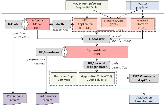
as depicted in Figure 1. This flow is rigorous, automated and allows fine-grain analysis of final hardware/software system dynamics. It is rigorous because it is based on formal models described in BIP [BBS06], with precise semantics that can be analyzed by using formal techniques. A system model in BIP is derived by progressively integrating constraints induced on application software by the underlying hardware platform. The system construction method has been introduced in [BB+11a]. The application software and the abstract model of the platform are initially defined using DOL [TBHH07]. In contrast to ad-hoc modeling approaches, the system model is obtained, in a compositional and incremental manner, from BIP models of the application software and respectively, the hardware architecture, by application of (automated) source-to-source transformations that are proven correct-by-construction. The system model describes the behavior of the mixed hardware/software system and can be simulated and formally verified using the BIP toolset. Moreover, it can be used as a basis for automatic code generation for the target platform.
Figure 1 : The BIP/DOL Design Flow in SMECY
We experiment the design flow above on the parallel software model derived from a sequential version of the HMAX models algorithm [RP99] developed at Hellenic Airspace Industries. We target implementations on the P2012 platform [STM10]. P2012 is a high performance, embedded multicore platform currently developed by STMicroelectronics. Although the hardware is not yet physically available, P2012 is supported by compilation and virtual simulation tools. Using the system model and the associated performance analysis tools, we are able to obtain, in a fully automatic way, fine-grained performance results for various implementations. Such results provide helpful insights to a software developer both for the selection of the right parallel decomposition and its optimal mapping on the given platform.
Building faithful system models is mandatory for performance evaluation. Simulation-based methods use ad-hoc executable system models such as [KDVW97] or tools based on SystemC [MGN03]. The latter provide cycle-accurate results, but in general, they have long simulation time as a major drawback. As such, these tools are not adequate for thorough exploration of hardware architecture dynamics neither for estimating effects on real-life software execution. Alternatives include trace-based co-simulation methods as used in Spade [LSWD01] or Sesame [EPTP07]. Additionally, there exist much faster techniques that work on abstract system models e.g., Real Time Calculus [TCN02] and SymTA/S [H05]. They use formal analytical models representing a
system as a network of nodes exchanging streams. The dynamics of the execution platform can be usually over-simplified and characterized by execution times. Nonetheless, these techniques allow usually estimation of pessimistic worst-case quantities (delays, buffer sizes, etc) and moreover, they require an abstract model of the application software. Building such abstract models requires a significant modeling effort and, if done manually, the construction can be error-prone and lead to inaccurate models. Similar limitations exist in performance analysis techniques based on Timed-Automata [AAM06, SBM09]. These can be used for modeling and solving scheduling problems. An approach combining simulation and analytic models is presented in [KBPT06], where simulation results can be propagated to analytic models and vice versa through adequate interfaces.
The paper is organized as follows. Section 2 introduces the HMAX models algorithm. Section 3 introduces the target platform, that is, the P2012 many-core developed by STMicroelectronics. Section 4 introduces the modeling formalisms used and the system model construction method. The implementation and experimental results obtained on the HMAX mapped on P2012 platform are presented in sections 5 and 6. Section 7 concludes and provides ongoing and future work directions.
2. HMAX Algorithm
HMAX is a powerful computational model of object recognition [RP99] which attempts to model the rapid object recognition of human brain. Hierarchical approaches to generic object recognition have become increasingly popular over the years [SWP05, ML08], they indeed have been shown to consistently outperform flat single-template (holistic) object recognition systems on a variety of object recognition task. Recognition typically involves the computation of a set of target features at one step, and their combination in the next step. A combination of target features at one step is called a layer, and can be modeled by a 3D array of units which collectively represent the activity of set of features (F) at a given location in a 2D input grid.
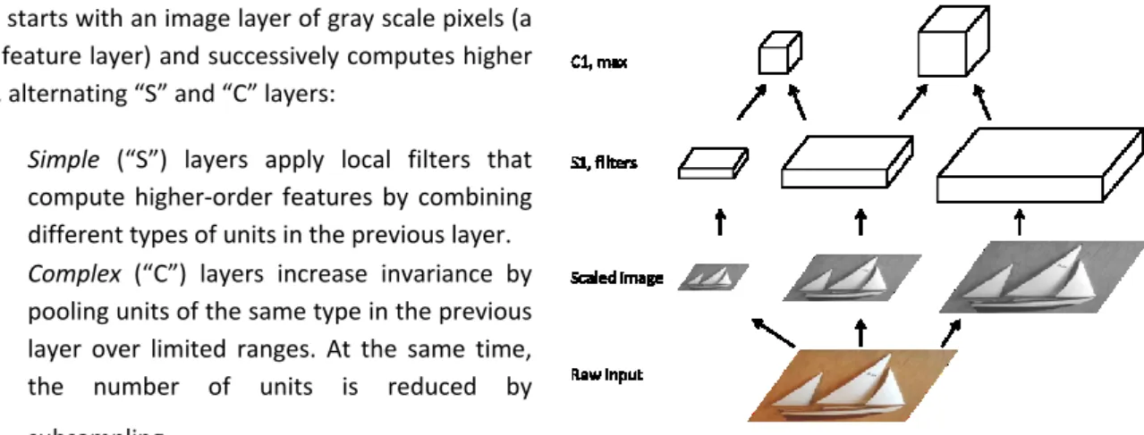
HMAX starts with an image layer of gray scale pixels (a single feature layer) and successively computes higher layers, alternating “S” and “C” layers:
Simple (“S”) layers apply local filters that compute higher-order features by combining different types of units in the previous layer. Complex (“C”) layers increase invariance by
pooling units of the same type in the previous layer over limited ranges. At the same time, the number of units is reduced by subsampling.
In our case study experiment, we only considered the
two first layers of the HMAX model algorithm. In a preprocessing phase, the input raw image is converted to gray scale input (only one input feature: intensity at pixel level) and the image is then sub-sampled at several resolutions. For the S1 layer, a battery of three filters is applied to the sub-sampled images (three features) and finally for C1 layer we take the spatial max of computed filters across two successive scales.
In this application model, parallelism can be exploited at several levels. First at the layer level, independent features can be computed simultaneously. Second, at the pixel level, the atomic computation of contribution to a feature may be distributed among computing resources. In the scope of this paper, we will consider parallelism at the layer level.
3. P2012 Platform
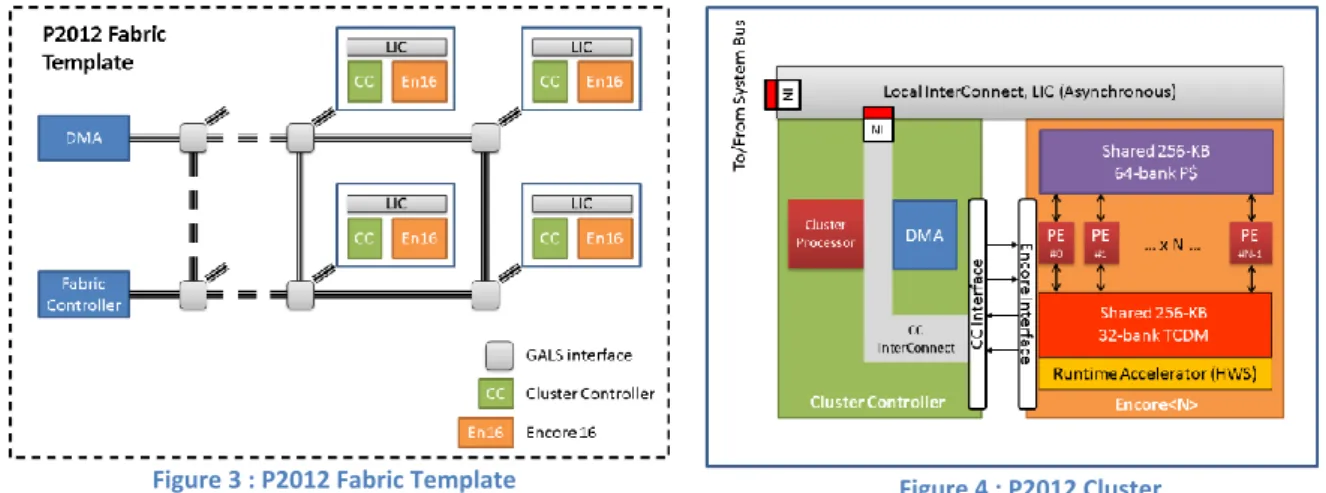
Platform 2012 (P2012) [STM10] is an area and power efficient many-core computing fabric, jointly developed by STMicroelectronics and CEA. The P2012 computing fabric is highly modular, as it is based on multiple clusters implemented with independent power and clock domains, enabling aggressive fine-grained power, reliability and variability management. Clusters are connected via a high-performance fully-asynchronous network-on-chip (NoC), which provides scalable bandwidth, power efficiency and robust communication across different power and clock domains. Each cluster features up to 16 tightly-coupled processors sharing multi-banked level-1 instruction and data memories, a multi-channel advanced DMA engine, and specialized hardware for synchronization and scheduling acceleration. P2012 achieve extreme area and energy efficiency by aggressive exploitation of domain-specific acceleration at the processor and cluster level. In the scope of this case study, each processor has been specialized with modular extensions dedicated to floating-point unit computation. Other extension such as vector units or other special-purpose instructions may also be chosen at design-time.
Figure 3 : P2012 Fabric Template Figure 4 : P2012 Cluster
P2012 is based on a modular infrastructure as depicted in Figure 3. Fabric-level communication is based on an asynchronous NoC organized in a 2D mesh structure. The routers of this NoC are implemented in a Quasi-Delay-Insensitive (QDI) asynchronous (clock-less) logic. They provide a natural Globally Asynchronous Locally Synchronous (GALS) scheme isolating the clusters logically and electrically. The number of clusters is a parameter of the fabric. A configuration up to 32 clusters is supporter in the current implementation. One important characteristic of the fabric is that all local storage at the cluster level is visible in a global memory map, which also includes memory-mapped peripherals. In this non-uniform memory architecture (NUMA), remote memories (off-cluster or off-fabric) are expensive to access. For this reason, DMA engines are available for hardware-accelerated global memory transfers. At the fabric level, a configurable number of I/O channels, implemented via multiple DMAs, can be used for connecting the fabric to the rest of the SoC. Finally, a fabric controller serves as the control interface between the SoC and the fabric.
A P2012 cluster (Figure 4) aggregates a multi-core computing engine, called Encore and a cluster controller. The Encore cluster includes a number of processing elements (PEs) varying from 1 to 16. Each PE is built with a highly configurable an extensible processor called STxP70-v4. It is a cost effective and customizable 32-bit RISC core supported by comprehensive state-of-art toolset. The Encore 16 PEs do not have private data caches or memories, therefore avoiding memory coherency overhead. Instead, the PEs can directly access a L1-shared program cache (P$) and a L1-shared tightly coupled data memory (TCDM). Each core therefore has two 64 bit-ports to the shared memories, a read-only instruction port and a read/write data port. The P$ cache is a 256 KB, 64-bank, direct mapped cache memory while the TCDM is a 256-KB, 32-bank memory. The P$ and the TCDM have been architected with a banking factor of 4 and 2, respectively. The P$ and the TCDM can therefore support a throughput of one instruction fetch and one data access per PE on each clock cycle. Encore provides
runtime acceleration by the means of the Hardware Synchronizer (HWS). Various synchronization primitives such as semaphores, mutexes, barriers, joins, etc. can be implemented using accelerated support of the HWS. The cluster controller (CC) consists of a cluster processor subsystem, a DMA subsystem, a CC interconnect and several interfaces: one to the Encore 16 PEs and one to the asynchronous NoC. The cluster processor is designed around a STxP70-V4 dual-issue core without extension and with 16-KB P$ and 16-KB of local memory. The Platform 2012 Development Kit provides support for several platform programming models (PPM). Standards-based programming models are based on industry standards that can be implemented effectively on P2012. The supported standards are OpenMP and OpenCL. Another supported PPM is called Native
Programming Layer (NPL). NPL is an API which closely coupled the platform capabilities. It allows the highest
level of control on application to resource mapping at the expense of abstraction and platform independence. The P2012 SDK also features platform models for the execution and the simulation of applications running on the P2012 platform. For the scope of this paper, we used a mono-cluster simulator of the fabric and an Encore engine featuring 16 PEs. We targeted the NPL for fine-tuned control of the deployment of the application on the platform, and to achieve better performances.
4. System Level Modeling
We briefly recall hereafter the construction of a mixed software/hardware system model introduced in [BB+11a]. The flow of the construction is illustrated in Figure 1. The method takes as inputs representations of the application software, the hardware platform and the mapping. These inputs are provided using the concrete formalism available in the DOL framework [TBHH07]. The output is the system model in BIP framework [BBS06]. The construction breaks down into several well identified translation and model transformation phases operating on DOL and BIP models.
DOL (Distributed Operation Layer) [TBHH07]) is a framework devoted to the specification and analysis of mixed hardware systems. DOL provides languages for the representation of particular classes of applications software, multi-processor architectures and their mappings. In DOL, application software is defined using a variant of Kahn process network model. It consists of a set of deterministic, sequential processes (in C) communicating asynchronously through FIFO channels. The hardware architecture is described as interconnections of computational and communication resources such as processors, buses and memories. The mapping associates application software components to resources of the hardware architecture, that is, processes to processors and FIFO channels to memories.
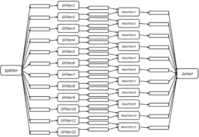
Figure 5 presents the process network model constructed from the S1 layer of the HMAX models algorithm. It contains processes Splitter, GFilter1 … GFilter12, MaxFilter1 … MaxFilter11 and Joiner. The Splitter builds the 12 scales of the input image and dispatches them to Filters. Each GFilter1 … GFilter12 implements a 2D-Gabor filter with different orientation. Their results are then sent, feature by feature, to MaxFilters. Each MaxFilter convolves outputs produced by two adjacent GFilters. The results are finally gathered by the Joiner.
For the scope of this paper, we target a simplified, preliminary version of the P2012 platform. This version consists of a mono-cluster version of the P2012 fabric and an Encore engine featuring 16 PEs. Figure 6 presents the abstract model of this platform in DOL.
Splitter Joiner GFilter1 GFilter2 GFilter3 GFilter4 GFilter5 GFilter6 GFilter7 GFilter8 GFilter9 GFilter10 GFilter11 GFilter12 MaxFilter1 MaxFilter2 MaxFilter3 MaxFilter4 MaxFilter5 MaxFilter6 MaxFilter7 MaxFilter8 MaxFilter9 MaxFilter10 MaxFilter11
Figure 5 : KPN model of the HMAX S1-C1 layers in DOL
Figure 6 : Abstract model of a P2012 cluster in DOL
BIP (Behavior-Interaction-Priority) [BBS06, BB+11a] is a formal framework for building complex systems by coordinating the behavior of a set of atomic components. Behavior is defined as automata or Petri nets extended with data and functions described in C/C++. The description of coordination between components is layered. The first layer describes the interactions between components. The second layer describes dynamic priorities between interactions and is used to express scheduling policies. BIP has clean operational semantics that describe the behavior of a composite component as the composition of the behaviors of its atomic
components. This allows a direct relation between the underlying semantic model (transition systems) and its implementation. The BIP toolset [BIPa, BIPb] includes a rich set of tools for modeling, execution, analysis (both static and on-the-fly) and transformations of BIP models. It provides a dedicated programming language for describing BIP models. The front-end tools allow editing and parsing of BIP programs, followed by code generation (in C/C++). The code can be used either for execution or for performance analysis using backend simulation tools.
As an example, Figure 7 presents the model of a 2D-Gabor filter as an atomic component in BIP. This component consists of 6 control locations (START, S1,... S4, DETACH) and two ports, DOL_read and DOL_write.
NDPF_state, size and address are local data (variables) of the component. The variables address and size are
associated with the ports. The transitions are either internal transitions (internal_step) where local computation and updates are made, or port interactions, where the component exchanges data and synchronizes with the other BIP components.
The system model embodies the hardware constraints into the software model according to the mapping. The construction of the system model in BIP is obtained by a sequence of translations and transformations of the DOL representations, as follows:
1. automatic translation of the application software in DOL into a BIP model. The translation is structural: processes and FIFO channels in DOL are translated into atomic components in BIP, connections in DOL are translated into connectors in BIP.
2. automatic translation of the hardware architecture model in DOL into a BIP model. The translation is also structural: hardware resources (processor, memory, bus, etc) are translated into BIP components, hardware interconnections are translated into connectors in BIP.
3. construction of an initial, abstract system model using source-to-source transformation of the previous two models and composition according to the mapping.
4. refinement of the previous system model by including specific timing information about the execution of the software on the platform.
All the transformations above preserve functional properties of the application software model. Moreover, the system model includes specific timing constraints for execution of the application software on the hardware platform. These constraints are obtained by cross compiling the application model into executable code for the target and measuring the execution time of the elementary blocks of code (e.g., BIP transitions). The timing information is integrated in the system model through the source-to-source transformation done in last refinement step (number 4 in the list above).
For experiments, we restrict ourselves to the S1 layer of the HMAX models algorithm. The process network in DOL consists of 14 processes and 24 FIFO channels. This DOL model is about 700 lines of XML (defining the process network structure) and 1500 lines of C (defining the process behavior). The software model in BIP is constructed automatically from the DOL model. It consists of 38 atomic components interconnected using 48 connectors. The BIP software model is about 2000 lines of BIP code. The system model obtained by deploying the S1 layer on a single P2012 cluster consists of 125 atomic components interconnected using about 1500 connectors. The total BIP description totalizes about 13000 lines of BIP code. This description is compiled into about 50000 lines of C++ code, used for simulation and performance analysis, as explained below.
5. Performance Analysis on the System Model
The system model captures, besides the pure functionality of the application software, all the non-functional constraints induced on it by the target platform. The system model can therefore be used to analyze non-functional properties such as contention for buses and memory accesses, transfer latencies, contention for processors, etc. In the proposed design flow, these properties are evaluated by simulation of the system model extended with observers. Observers are regular BIP components that sense the state of the system model and collect pertinent information with respect to the properties of interest i.e., the delay for particular data transfers, the blocking time on buses, etc. Actually, we provide a collection of predefined observers allowing to monitor and record specific information for most common non-functional properties.
Simulation is performed by using the native BIP simulation tool [BIPa]. The BIP system model extended with observers is used to produce simulation code that runs on top of the BIP engine, that is, the middleware for execution/simulation of BIP models. The outcome of the simulation with the BIP engine is twofold. First, the information recorded by observers can be used as such to gain insight about the properties of interest. Second, with some caution3, the same information can be used to build much simpler, abstract stochastic models. These models can be further used to compute probabilistic guarantees on properties by using statistical-model checking. This two-phase approach combining simulation and statistical model-checking has been successfully experimented in a different context [BB+10]. Moreover, it is fully scalable and allows (at least partially) overcoming the drawbacks related to simulation-based approaches, that is, the long simulation times and the lack of confidence in the results obtained.
For example, in our application, the execution time of 2D-Gabor filters on P2012 PEs ranges from 220 106 to 0,68 106 cycles, depending on the size of the input image (ranging from 100x100 to 15x15 pixels). By using these values in the system model, the total execution time of the S1 layer is estimated as 225 106 cycles. This overall execution time is negatively impacted by the long access time (i.e., about 100 cycles) to the L3 memory (where all FIFOs are mapped) as well as by the bus contention. A slightly better result is obtained if the FIFOs are all mapped into the TCDM memory. In this case, the memory access time is about 1 cycle and there is no more contention. The total execution time reduces to about 220 106 cycles. However, such a mapping is not feasible due to memory size constraints, that is, FIFOs cannot fit all simultaneously within the TCDM memory.
6. Implementation and experiments on P2012
We are developing an infrastructure for generating code from the BIP system models. We seek for portability and therefore, the generated code targets a particular runtime that can be eventually deployed and run on different platforms, including P2012.
The runtime provides generic API for thread management, memory allocation, communication and synchronization. The generated code is not bound to any particular platform and consists of the functional code and the glue code. The functional code implements the application tasks, that is, processes in the original DOL/BIP models. For each task, a C file is generated that contains the description of the data and a thread routine describing the behavior. The behavior is a sequential program consisting of computation statements and communication calls, that is, invocation of particular API provided by the runtime. The glue code implements the main routine that handles the allocation of threads to cores and the allocation of data to memories. Threads are created and allocated to processors according to the mapping description. Moreover, data allocation consists of allocation of the thread stacks and allocation of FIFO queues for communication. All these operations are realized by using the API provided by the runtime.
As shown in Figure 1, the generated code is finally compiled by the native platform compiler. The code is linked with the runtime, hardware dependent library, to produce the binary executable(s) for execution on the platform. For our experiments, we have used the Native Programming Layer (NPL), a common runtime implemented for both P2012 and MPARM platforms [BBB+05, MPS]. The generated code has been run on virtual platforms available in the P2012 SDK 2011.1, namely GEPOP - the P2012 POSIX-based simulator - and the P2012 TLM simulator.
7. Conclusions
We illustrate a rigorous design flow for development of application on manycore platforms. We consider one of the most challenging case studies provided in the SMECY project, namely the implementation of the HMAX models algorithm for object recognition on P2012, a highly modular, embedded manycore platform developed by STMicroelectronics. Given the application software, an abstract model of the target platform and a mapping, our design flow allows (1) to derive a faithful system model for performance analysis and (2) to produce implementations. The flow is fully automated and mainly supported by the BIP toolset.
This work is being extended in several directions. First of all, we are refining the input DOL model of the HMAX in order to exhibit more fine-grain parallelism, i.e., within 2D-Gabor and Max filters. This refinement seems to be mandatory to increase overall runtime performances. Second, we plan to evaluate and target implementations on the latest P2012 SDK available, which features multi-cluster support as well as optimized runtimes. Third, regarding the design flow, we are working on extensions to richer hardware models, which include for example DMA controllers, bus bridges and/or NoC communication. Moreover, we plan to include and evaluate statistical model checking for system models consisting of multiple software applications running in parallel, following the method described in [BBB+10].
References
[AAM06] Y. Abdeddaim, E. Asarin, and O. Maler. Scheduling with Timed Automata. Theoretical Computer Science, 354:272–300, 2006.
[A07] D. Abhijit et al. A Next-Generation Design Framework for Platform-Based Design. In DVCon’07.
[BBB+05] L. Benini, D. Bertozzi, A. Bogliolo, F. Menichelli, and M. Olivieri. MPARM: Exploring the Multiprocessor
SoC Design Space with SystemC. J. VLSI Signal Processsing Systems, 41:169–182, 2005.
[BBB+10] A. Basu, S. Bensalem, M. Bozga, B. Caillaud, B. Delahaye, and A. Legay. Statistical Abstraction and
Model-Checking of Large Heterogeneous Systems. In FMOODS/FORTE’10, pages 32–46, 2010.
[BBB+11a] A. Basu, S. Bensalem, M. Bozga, J. Combaz, M. Jaber, T. Nguyen, and J. Sifakis. Rigorous
Component-Based Design using the BIP Framework. IEEE Software, Special Edition – Software Components beyond
Programming – from Routines to Services, 2011.
[BBB+11b] P. Bourgos, A. Basu, M. Bozga, S. Bensalem, J. Sifakis, and K. Huang. Rigorous System Level Modeling
and Analysis of Mixed HW/SW Systems. In MEMOCODE’11, pages 11–20. IEEE/ACM, 2011.
[BBS06] A. Basu, M. Bozga, and J. Sifakis. Modeling Heterogeneous Real-time Components in BIP. In SEFM’06, pages 3–12, 2006.
[BIPa] http://www-verimag.imag.fr/bip-system-designer.html. [BIPb] http://www-verimag.imag.fr/bip-tools,93.html.
[EPTP07] C. Erbas, A. D. Pimentel, M. Thompson, and S. Polstra. A Framework for System-Level Modeling and
Simulation of Embedded Systems Architectures. EURASIP J. Embedded Systems, 2007:2–2, 2007.
[H05] R. Henia et al. System-Level Performance Analysis – The SymTA/S Approach. In IEEE Proceedings Computers and Digital Techniques, volume 152, pages 148–166, 2005.
[HSKM08] C. Haubelt, T. Schlichter, J. Keinert, and M. Meredith. SystemCoDesigner: Automatic Design Space
Exploration and Rapid Prototyping from Behavioral Models. In DAC’08, pages 580–585, 2008.
[Kah74] G. Kahn. The Semantics of a Simple Language for Parallel Programming. Information Processing, pages 471–475, 1974
[KDVW97] B. Kienhuis, E. F. Deprettere, K. A. Vissers, and P. Wolf. An Approach for Quantitative Analysis of
Application-Specific Dataflow Architectures. In ASAP, pages 338–349, 1997.
[KPBT06] S. Künzli, F. Poletti, L. Benini, and L. Thiele. Combining Simulation and Formal Methods for
System-Level Performance Analysis. In DATE’06, pages 236–241, 2006.
[LSWD01] P. Lieverse, T. Stefanov, P. van der Wolf, and E. Deprettere. System Level Design with SPADE: an
M-JPEG case study. ICCAD’01, pages 31–38, 2001.
[MGN03] I. Moussa, T. Grellier, and G. Nguyen. Exploring SW Performance using SoC Transaction-Level
Modeling. In DATE, pages 20120–20125, 2003.
[ML08] J. Mutch and D.G. Lowe. Object Class Recognition and Localization using Sparse Features with Limited
Receptive Fields, IJCV 2008.
[MPS] http://www-micrel.deis.unibo.it/sitonew/research/mparm.html.
[RP99] M. Riesenhuber and T. Poggio. Hierarchical Models of Object Recognition in Cortex. Nature Neuroscience, 1999
[SBM09] R. Salah, M. Bozga, and O. Maler. Compositional Timing Analysis. In EMSOFT’09, pages 39–48, 2009. [STM10] STMicroeletronics & CEA, Platform 2012: A Many-core Programmable Accelerator for Ultra-Efficient
Embedded Computing in Nanometer Technology, 2010, White Paper.
[SWP05] T. Serre, L. Wolf, and T. Poggio. Object Recognition with Features Inspired by Visual Cortex, CVPR 2005. [TBHH07] L. Thiele, I. Bacivarov, W. Haid, and K. Huang. Mapping Applications to Tiled Multiprocessor
Embedded Systems. In ACSD, pages 29–40. IEEE Computer Society, 2007.
[TCN02] L. Thiele, S. Chakraborty, and M. Naedele. Real-time Calculus for Scheduling Hard Real-Time Systems. In ISCAS, volume 4, pages 101–104. IEEE, 2002.