Design and Development of a Multi-Shot Foam Projectile Toy
by Alan M. Skaggs
B.S., Mechanical Engineering (2005) B.S., Mathematics (2005) Southern Methodist University
Submitted to the Department of Mechanical Engineering in Partial Fulfillment of the Requirements for the Degree of
Master of Science in Mechanical Engineering at the
Massachusetts Institute of Technology May 2007
© 2007 Massachusetts Institute of Technology All rights reserved
Signature of Author... ...
-ýe ent 104 ;C
neg
Certified by... ... C. ... ...
David Wallace Associate Professor of Mechanical Engineering, MacVicar Fellow Thesis Supervisor
A ccepted by... Lallit Anand Chairman, Department Committee on Graduate Students
MASSACHUSETTS INS IT E
OF TECHNOLOGY
JUL
1 8 2007
LIBRARIES
Design and Development of a Multi-Shot Foam Projectile Toy
byAlan M. Skaggs
Submitted to the Department of Mechanical Engineering on May 23rd , 2007, in partial fulfillment of the
requirements for the degree of
Master of Science in Mechanical Engineering
Abstract
The goal of this research was to design and develop a working prototype of a new toy for Hasbro®'s Nerfe line of foam projectile toys. Several years ago, Hasbro approached the MIT CADlab about developing a new method for firing Nerfe foam balls. The hope was that a new approach would be generated from which a new platform of products could be developed. The result of the initial work was the development of Hopper Popper ActivationTM, which uses a bistable rubber spring to fire Nerf foam balls.
Due to its novel nature and the simplicity of its design, Hopper Popper Activation has since been integrated into a single projectile toy named the Atom BlasterTM, which reached the market in early 2007. Following the success of this project, Hasbro requested that a multi-shot projectile toy be developed that makes use of Hopper Popper ActivationTM, so that it may extend the platform of toys which use this new firing mechanism.
This thesis follows the product design process that led to the development of the Multi-Shot PopperTM, which incorporates Hopper Popper ActivationTM into a toy blaster capable of storing and rapidly firing multiple foam ball projectiles. In addition to using Hopper Popper ActivationTM, the Multi-Shot PopperTM was required to fulfill several other requirements, including specific safety and performance specifications, while still remaining a fun and enjoyable toy.
The design team created a series of iterative sketch models to test different mechanisms and methods of accomplishing the stated functional requirements. At each stage of the process, the successes and shortcomings of the current model were assessed and small scale brainstorming sessions were held to generate new concepts. These new concepts were combined with the successful features of the previous models until a final alpha-prototype was created which meets the customer and user requirements.
Thesis Supervisor: David Wallace
Title: Associate Professor of Mechanical Engineering MacVicar Fellow, Co-Director MIT CADlab
Acknowledgments
This project could not have happened without the help of many people, to whom I am greatly indebted. I would like to thank Barry Kudrowitz, James Penn, Matt Blanco, Bill Fienup, and Andrew Greenhut for their work on all things popper-related. Without all of your work, this project would never have been completed. Thanks to the sponsor, Hasbro®, for continuing to support the work of other students in the CADlab. Thanks to Prof. David Wallace for supervising my work and for setting an example of dedication to his work and his students that all professors should strive toward. Thanks to Dr. David Willis, Dr. Bijan Mohraz and Dr. Bryan Rigg - three of my favorite undergrad professors - for everything you taught me and for encouraging me to do great things. Thanks to all the members of the CADlab -Tom, lason, Sittha, Monica, Mika, Barry, Wei, Sangmok, James, Amy, Paul, Keiko - who made it such a fun place to work (and live?) during my time here. I think you would be extremely hard pressed to find another lab anywhere full of such good-natured and genuinely nice people (and a dog!). Thanks to David Hasselhoff, who would often make surprise appearances in lab, keeping me upbeat. Thanks to Maureen 'The Big Screw' Lynch and Leslie 'E-mail' Regan for having all of the answers and the patience to field the questions. Thanks to MIT for teaching me humility. I never knew just how much I didn't know until I came here and everybody else knew it all. I owe a large debt of gratitude to all of my friends, too many to list here, who have helped me more than they know whenever personal and academic problems/crises arose. In addition to my friends from back home, I was very lucky to meet such a great group of people so soon after arriving at MIT, and these last two years would have been pretty miserable without all of you. Special thanks go to Mike and Biff for being great roommates and for teaching me the value of marathons and birthday cakes, respectively.
Most of all, I would like to thank my parents for always believing in me and showing me such unfailing love, encouragement, and support. I never would have made it this far without you. You mean the world to me and I love both of you dearly.
Table of Contents
1 Introduction ... 11
1.1 Objective... 11
1.2 Outcom e... 11
1.3 About this Thesis ... 12
2 Planning ... 13
2.1 Custom er N eeds ... 13
2.2 Standards and Safety... 15
2.3 State ofthe A rt... 16
3 Concept D evelopm ent ... 19
3.1 Introduction/Ideation... 19
3.2 Background ... 19
3.2.1 H opper Popper A ctivation ... 20
3.3 M odel Progression ... 23 3.3.1 W ooden M odel... 24 3.3.1.1 Popper Inversion... 24 3.3.1.2 Storage/Loading ... 26 3.3.1.3 Triggering ... 27 3.3.2 M etal M odel... 27 3.3.2.1 Popper Inversion ... 28 3.3.2.2 Storage/Loading... 31 3.3.2.3 Triggering ... 32
3.3.3 Rapid Prototyped (RP) M odel ... 32
3.3.3.1 Popper Inversion ... 33 3.3.3.2 Storage/Loading ... 34 3.3.3.3 Triggering ... 36 4 Conclusion ... 41 4.1 Sum m ary ... 41 4.2 Future W ork ... 41 Appendix A ... 43
A.2 Final Shot Popper CAD Model... ... 56
List of Figures
1-1: Final Multi-Shot Popper Iteration Multi-Shot PopperTM...11
2-1: Nerft Atom BlasterTM...17
2-2: Nerf Ball-BlasterTM and ReactorTM...18
3-1: Popper in Inverted and Natural States...20
3-2: Inverted Popper with Nerf foam ball...21
3-3: Direction of resistance preventing full popper inversion...21
3-4: Cross Section of Popper Holder...22
3-5: Popper Holder with and without popper...22
3-6: W ooden M odel...24
3-7: Eye-bolt through popper...25
3-8: Top view of Wooden Model showing eye-bolt through popper...25
3-9: M etal M odel...28
3-10: Exchange of bolt during popper inversion...30
3-11: Visualization of foam balls in storage chamber...31
3-12: Primary ball pinned against bolt...31
3-13: Primary ball in fully loaded position...32
3-14: Fully assembled RP model...33
3-15: Rack and pinion system...33
3-16: Elbow Joint closed and open to allow loading...35
3-17: Handle and trigger...36
3-18: Triggering Assembly...37
3-19: Trigger...37
3-20: CAD Model displaying motion of trigger assembly during triggering...39
Chapter 1
Introduction
1.1
Objective
The goal of this research was to design and develop a projectile toy able to store and fire multiple standard-size Nerfe balls using the Hopper Popper ActivationTM technology previously developed in the MIT CADlab [1]. The developed product was required to comply with all applicable safety standards provided by the sponsor company Hasbro® Incorporated, while at the same time satisfying all stated and implied customer needs, and maintaining the requisite level of fun for the user.
1.2
Outcome
After several model and design iterations, a working final prototype of the Multi-Shot PopperTM was implemented, meeting the customer needs, as they are understood, while also satisfying the applicable safety standards. The Multi-Shot PopperTM is unique amongst projectile toys in that it is the only toy that is able to store and fire multiple projectiles using Hopper Popper ActivationTM system as the firing mechanism.
1.3
About this Thesis
A structured method of product design, as described in Ulrich and Eppinger's text Product Design and Development [4], was used by the design team throughout the development of the Multi-Shot PopperTM. It is beneficial to the development of any successful product to use a structured design method, to reduce the risk of proceeding with a flawed design. This thesis provides documentation of the sketch models that were developed, and shows how the design of key modules progressed from one stage to the next. This approach should allow the reader to follow the development of the Multi-Shot PopperTM design from start to finish and thereby gain a fuller understanding of not only how it works, but why it was designed to work in the way that it does.
Chapter 2
Planning
The planning phase involved all work done before the actual design of the product began. It was a necessary first step in the product design process, as it was the stage during which the key design considerations were defined, including:
- Specifications to be met by the product
- Limitations (safety or otherwise) to be placed on the product - Target market for the product
- Existing competitors (state of the art)
Keeping these considerations in mind as the product design process progressed made it easier for the design team to stay focused on feasible ideas and prevented the team from exploring the development of a design that was clearly deficient in any of these areas, which would have rendered it unacceptable in the final analysis.
2.1
Customer Needs
Before any drawings were made or parts were sketched, it was necessary to identify the users of the product and determine their needs. In the case of this project, the sponsor and the end-user were different, each with their own set of needs, which both had to be taken into account.
The sponsor, Hasbro, presented the design team with several specifications to be met, encompassing the functionality as well as the safety of the product. The safety needs will be detailed in the Standards and Safety section. The functional specifications for the product were broad enough to allow for the design team to work with a relatively large amount of freedom, encouraging the exploration of a variety of design approaches to meet the customer needs.
The key sponsor needs were as follows:
- The product uses the Hopper Popper ActivationTM system as the discharge mechanism
- The product can store multiple balls, and once loaded, can fire these balls in rapid succession
- The product is not overly complex, either in its design or its use
- The product makes use of a familiar "pump-action" style of motion
- The product is safe and meets all applicable safety specifications as listed in the Standards and Safety section
An additional sponsor requirement was that the product be fun, though this is subjective and difficult to quantify. While it was an important requirement to keep in mind, it is not listed above since the team decided that this would be achieved as a natural consequence of meeting the other specifications.
In addition to the needs of the sponsor, it was important to consider the specific needs of the actual end-user, or customer. Before beginning any work on the design of the product, it was essential to know who the actual end-user would be and what his/her needs were as they related to the product. The type of customer being targeted will, in most cases, greatly affect the direction of the design process, as the customer needs will vary across different segments of the population. For this project, the target user was defined to be children over the age of 5. Accordingly, the following customer needs were taken into account:
- The product is simple to use and does not require complicated instructions - The required loading force is within the customer's limits (< 20 lb-f)
Using these sponsor and customer needs, the design team moved forward with the following mission statement to define the design task:
To design and develop a safe, fun, multi-projectile toy that makes use of the Hopper Popper ActivationTM system to fire Nerfi foam balls.
2.2
Standards and Safety
Anytime a product is being designed, it is necessary to make safety a priority. The possibility for injury must be kept to a minimum through careful consideration of the need for safety throughout the design process. At the same time, a careful balance between safety and performance must be struck so as to ensure that this emphasis on safety does not detract from the enjoyment of the product by the user.
Safety is especially important when designing a product intended for use by children. As a general rule, children (and perhaps even adults!) can not be relied upon to read written safety warnings, or expected to truly appreciate the risks involved in not obeying these warnings. Therefore, it was incumbent upon the design team to create a product with a sufficiently high level of safety that a parent would feel comfortable buying this toy for his/her child.
In addition to the special safety risks presented by a product geared towards children, a toy that fires projectiles bears added risk for injury (especially eye injury). With this in mind, Hasbro® applies their own set of safety standards for projectiles, detailed in a document entitled, "Corporate Quality Assurance, Safety and Reliability Specification, SRS-045, Projectiles" [2]. The document can be found in its entirety in Appendix A.1.
From the beginning of the design process, it was known that the Multi-Shot PopperTM would use stored energy to fire projectiles. This meant that the projectiles (Nerf foam balls) were propelled by a discharge mechanism (Hopper Popper ActivationTM) capable of storing and releasing energy under the control of the user. In other words, the toy itself, and not the user, would define the amount of energy imparted to the projectiles. This is in contrast to projectiles without stored energy, such as a Frisbee, boomerang, or football, which are propelled solely by the energy imparted by the user.
Listed below are synapses of the sections of this document that applied to the Multi-Shot PopperTM. Since the type of projectile was defined to be the standard Nerfe foam ball, any sections relating only to the features of the projectile itself were assumed to be
satisfied.
Impact Test for Projectiles
Projectiles shall be propelled by their discharge mechanism six times into a concrete block wall (or equivalent surface) at a distance of one foot plus the length of the
projectile from the front end of the discharge mechanism while the discharge mechanism is aimed perpendicular to the wall. This test assures that the integrity of the projectiles will not be compromised upon impact.
Improvised Projectile Testing
The discharge mechanism must not be capable of discharging projectiles other than the projectile specifically designed for use with the discharge mechanism. Some of the more common improvised projectiles include: pens, pen caps, markers, marker caps, paper clips, pen refills, batteries, marbles, and pebbles.
Unexpected Discharging of Projectiles
The discharge mechanism must not discharge projectiles in an unexpected or inordinately delayed fashion. During normal use, only the activating button, lever or switch must be capable of discharging the projectile. The projectile must be discharged within four seconds of launch activation.
Kinetic Energy and Kinetic Energy Density
Any projectile fired from a toy that has a kinetic energy above 0.08 Joules must have an impact surface made of a resilient material. If the projectile kinetic energy exceeds 0.08 Joules, the projectile Kinetic Energy Density must be determined by dividing the kinetic energy of the projectile by its contact area. This Kinetic Energy Density must not
2
exceed 1600 J/m2
2.3
State of the Art
The roots of this project were found in the previous work done in the CADlab to develop a novel line of projectile toys, resulting in the development of the Hopper Popper ActivationTM system. Documentation of related work done in the CADlab can be found in the theses of Barry Kudrowitz and Bill Fienup [1], Matt Blanco [7], and Andrew Greenhut [8].
In their text Product Design and Development [4], Ulrich and Eppinger define the four types of product development projects as follows:
- New product platforms involve creating a new family of products based on a common platform.
- Derivatives of existing product platforms extend an existing product platform to address different needs.
- Incremental improvements to existing products are slight changes to enhance or eliminate flaws.
- Fundamentally new products are radically different products or production technologies to address new or unfamiliar markets, usually at a high risk.
At the time this multi-projectile project was proposed, the Hopper Popper ActivationTm system had not yet reached the market in any form, so there were no directly comparable products to the Multi-Shot Popperm. In the intervening time period, the Nerf* Atom BlasterTM reached the market, becoming the first consumer product to use Hopper Popper ActivationTm in this way. However, the Atom Blasterm
was designed to hold and fire only a single Nerf ball, and was aimed at younger customers, so it could not be seen as a direct competitor to the Multi-Shot PopperTm .
Rather, these two products were part of the same family of products based on a common platform. Thus, the development of the Multi-Shot PopperTm fell under the category of
derivates of existing product platforms, as it extended the Nerf* and Hopper Popper ActivationTM product platforms to cover the storage and firing of multiple projectiles.
I.
I
I 2-1: Nerf Igure
For the purpose of comparison, the design team deemed that the closest competitors, which would comprise the state of the art technology, would be any products able to store and fire multiple Nerf* balls without the use of an electric motor. The two products which best fit this description were the Nerf4 Ball Blaster, released in 1999, and its 2006 redesign, the Nere Reactor, both shown in Figure 2-2. While these products used stored air pressure as the discharge mechanism, the overall function was the same, allowing for a straightforward comparison.
(a)
(b)
Chapter 3
Concept Development
3.1
Introduction/Ideation
The customer needs defined several aspects of the design, such as the use of pump action, ability to store multiple balls, and use of Hopper Popper ActivationTM as the firing mechanism. These elements created a general framework for what the finished product should look like and be able to accomplish. Equipped with this general definition, the design team was able to bypass the initial brainstorming session that often serves as the first stage of the product design process.
Instead, the design team conducted smaller scale brainstorming sessions on a modular level throughout the course of the design process. These sessions were used to develop different concepts for mechanisms or methods to perform a specific function or meet a certain need. The most promising concepts were then integrated into sketch models to test their feasibility, before a final prototype model was created, encompassing all of the necessary design elements.
3.2
Background
One feature that was guaranteed to be a part of the finished design was Hopper Popper ActivationTM as the firing mechanism, meaning that the rest of the design was generated around this one element. It was therefore necessary for the design team to become familiar with Hopper Popper ActivationTM. Understanding its capabilities, limitations, strengths and weaknesses made it easier for the design team to know how best to integrate this element into the rest of the design. To accomplish this, the design team used several different methods, including experimenting with Hopper Popper ActivationTM and consulting with Barry Kudrowitz, one of the primary developers of Hopper Popper ActivationTM. The theses of both Andrew Greenhut [8] and Barry
Kudrowitz and Bill Fienup [1] served as excellent resources, as they contained an in depth explanation of the development and behavior of Hopper Popper ActivationTM.
3.2.1 Hopper Popper Activation
The most important part of Hopper Popper ActivationTM, and the part that supplied the actual 'pop', was an injection molded bi-stable rubber toy called a "hopper popper," or "dropper popper." These toys will henceforth be referred to as "poppers."
When in its natural, non-inverted state, the popper resembled half of a hollow rubber sphere (similar to a cereal bowl), as shown in Figure 3-1a. However, the key to the popper was that it was capable of storing energy when inverted, as shown in Figure 3-l b.
(a) (b)
Figure 3-1: Poppers in the Natural (a) and Inverted (b) States [1]
The traditional intent for the popper was to make use of its own stored energy to launch itself, rather than to fire independent projectiles. When inverted and then dropped onto the ground or other surface, the popper would convert its stored energy into kinetic energy, launching itself into the air. In essence, the popper acted as both the projectile and the firing mechanism. However, if the popper was held in place when its stored energy was released, that energy could instead be transferred into the kinetic energy of a projectile. This was the realization that led to the development of Hopper Popper ActivationTM
. To accommodate standard Nerf foam balls, a popper with a diameter of
2.2 inches in its natural state was used, allowing a Nerf foam ball to rest in the inverted popper, as shown in Figure 3-2.
Figure 3-2: Inverted Popper with Nerfo foam ball [1]
Since the popper had never before been used in this manner, it was necessary to design a device to perform this function. Several considerations had to be taken into account during this process. The device, or popper holder, had to allow the popper to freely invert and return to its natural position while keeping the popper firmly in place. However, it could not provide excessive resistance, which would decrease the amount of
energy capable of being transferred to the projectile.
Additionally, when the popper was inverted, its rim diameter increased 0.4 inches radially [1], which had to be accounted for in the design of the popper holder. If this increased diameter was not accommodated, the popper would have been prevented from reaching its fully inverted state due to the restrictions of the holder, applying forces in the horizontal direction as shown in Figure 3-3.
Figure 3-3: Direction of resistance preventing full popper inversion
This presented multiple problems. If the popper never became fully inverted, it would never reach its second stable position, and the ball would be ejected as soon as it
was released by the user. Since all projectiles must be released in a controlled manner, allowing the popper to become fully inverted was essential. Furthermore, fully inverting the popper allowed it to store the most energy, increasing the firing distance of the projectile. Finally, the added resistance made it much harder to invert the popper, making inverting forces too high for a young user.
The final iteration of the popper holder incorporated a tight internal geometry to prevent unnecessary motion of the popper, while still allowing the popper to invert freely. Small rubber gasket segments were added at three points around the rim to keep the ball in place once loaded. Figure 3-4 illustrates a cross sectional view of the securing device with the popper itself appearing in blue as it fit inside the device. Figure 3-5 shows a SLS (selective laser sintering) prototyped version of the final iteration.
Figure 3-4: Cross Sectional view of Popper Holder [ 1]
(a) (b)
3.3
Model Progression
As a natural consequence of the design process, the design team created several iterative sketch models of the Multi-Shot PopperTM, each serving to illustrate and test different aspects of the design. After each model was produced, the positive and negative aspects were discussed and documented, and design improvements were suggested based on the performance of the model.
To help the design process proceed in an orderly manner, and to ensure that the end result would fulfill all necessary requirements, the major functions of the design were divided into three categories: Storage/Loading, Popper Inversion and Triggering. These categories represented all of the actions that the Multi-Shot PopperTM needed to perform.
While safety was one of the most highly ranked customer needs, it was not classified as a distinct category because it was not possible to separate safety from the other components of the design in that way. Listing safety as its own category would imply that it was not a factor in the other categories, allowing for the development of unsafe design elements. Attempting to go back and retroactively account for safety in inherently unsafe designs was not an efficient method for product design. Therefore, the design team was mindful of the safety requirements in each facet of the design.
What follows is a description of the models that were created, arranged in chronological order, along with how each model addressed the three major functional requirements listed above. By examining the design process through the progression of the whole models, and not merely the functional modules, it is easier to conceptualize how the modules worked together and how the design of the Multi-Shot PopperTM evolved. Reading about the process in true chronological order also makes it easier to follow the changes and progression made along the way, as each model acted as a step along the path of the product design process.
3.3.1 Wooden Model
The first significant model iteration will be referred to as the "wooden model," a sketch of which can be seen in figure 3-6. Though simple in appearance, this model addressed several functional issues, teaching the design team important lessons.
Figure 3-6: Sketch of Wooden Model
3.3.1.1
Popper Inversion
Prior to building the first model, the design team theorized different methods by which the popper could be inverted, while also fitting into the shape of a traditional blaster. The three most feasible possibilities were: Holding the Popper Holder stationary and pulling on the popper from behind; Holding the Popper Holder stationary and pushing a foam ball into the popper from the front with enough force to invert it; Holding a foam ball stationary and forcing the popper to invert around the ball by pushing the Popper Holder forward. Of these three methods, the first was selected as the most promising. With the second and third approaches, some of the energy exerted to invert the popper would have been lost by pushing into the foam ball, which would have deformed and absorbed energy.
The main purpose of this model was to test the feasibility of inverting the popper by pulling on it from behind while holding the Popper Holder stationary. Applying force to the popper from behind required a linkage connecting to the popper, which could be
,er
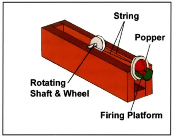
Firing
Plaform
accomplished either by rigid or flexible attachment, which was the second aspect of Popper Inversion being tested with this model. The design team chose to test string, a flexible attachment, as the linkage.
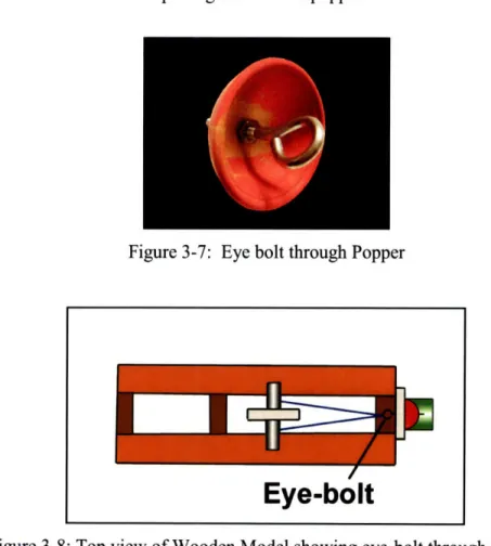
To make the attachment to the popper, the design team placed an eye-bolt through the hole in the center of the popper with the eye in back, fixing the bolt in place with a nut on either side of the popper. The string was tied to the eye of the bolt in back of the popper and then affixed in two locations to a shaft located farther back on the body of the model. This shaft was press fit through the center of a larger wheel, to which the inversion force could be applied. When the wheel was rotated, the shaft would rotate as well, winding the string around the shaft and pulling back on the popper.
Figure 3-7: Eye bolt through Popper
Figure 3-8: Top view of Wooden Model showing eye-bolt through popper
Several rubber bands were placed around the circumference of the wheel, which provided a high-friction surface to more easily apply force without slipping. To invert the popper, a small block of wood was pressed down upon the top of the wheel and
pulled backwards, using the desired pump action, and winding the string until enough force had been applied to invert the popper.
This model provided several key insights into the area of Popper Inversion. Most importantly, it showed that it was indeed possible to invert the popper from behind. Also, by using a large wheel on a smaller shaft to translate force to the popper, the user was
able to gain a mechanical advantage, reducing the required input force.
However, it also revealed the shortcomings of using string as the linkage material. When the string was being wound, it would stretch, absorbing energy and increasing the amount of energy required to invert the popper. Additionally, when the blaster was fired, the popper had to unwind some length of string, thus rotating the shaft and wheel, as it returned to its natural position, resisting the motion of the popper and decreasing the amount of energy imparted to the ball. This caused the balls to be discharged with a lower velocity.
An unexpected benefit of this approach was that the eye-bolt provided a solution to one of the major safety concerns. Having the front of the bolt extend through the front of the popper served two purposes. The first was to center the force of the popper in the middle of the ball when it was launched, and the second was to make it much more difficult to fire improvised projectiles. Most perceived improvised projectiles were small and would need to rest in the center of the popper to be fired at any appreciable velocity. Since the bolt occupied this position, any improvised projectiles would be restricted to the edge of the popper, where they would receive only a fraction of the converted kinetic energy from the discharging of the popper.
3.3.1.2
Storage/Loading
The secondary purpose of the model was to examine the suitability of a vertically oriented loading/storage enclosure. The storage device was a plastic tube held by hand in a vertical orientation above the firing platform. The tube could hold six foam balls, and contained a compression spring to force the balls out of the tube. In this orientation, while a single ball was in the firing position (from now on referred to as the "primary ball") and ready to be discharged by the popper, the remaining stored balls were resting
on top of one another, with the second ball to be fired ("secondary ball") resting on the primary ball.
Testing confirmed that it was possible to fire a ball in this configuration without a significant loss in velocity. This presented two benefits. First, the stored balls held the primary ball in place, keeping it from moving out of the firing position as the orientation of the blaster was changed. Second, using the stored balls to perform this task eliminated the need for a separate mechanism, simplifying the design.
Despite its useful lessons, the vertically oriented storage/loading tube was not seen as an appealing permanent option, as its appearance was obtrusive and it gave the blaster a clunky feel, reducing the perceived play value.
3.3.1.3
Triggering
The triggering in this model was performed simply by hand. The design team observed, as was discovered in previous work by Barry Kudrowitz and Will Fienup, that the closer to the center of the popper the force was applied, the less force was required to fire the popper. While no mechanical triggering mechanism was put in place, this knowledge aided in future development of a triggering mechanism.
3.3.2 Metal Model
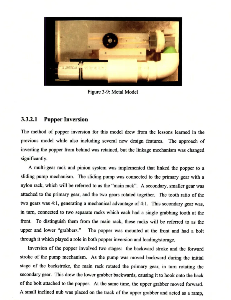
The metal model iteration represented a big leap forward from previous models in many respects and introduced for the first time several key design features which were present in the final design of the Multi-Shot PopperTM
Figure 3-9: Metal Model
3.3.2.1
Popper Inversion
The method of popper inversion for this model drew from the lessons learned in the previous model while also including several new design features. The approach of inverting the popper from behind was retained, but the linkage mechanism was changed significantly.
A multi-gear rack and pinion system was implemented that linked the popper to a sliding pump mechanism. The sliding pump was connected to the primary gear with a nylon rack, which will be referred to as the "main rack". A secondary, smaller gear was attached to the primary gear, and the two gears rotated together. The tooth ratio of the two gears was 4:1, generating a mechanical advantage of 4:1. This secondary gear was, in turn, connected to two separate racks which each had a single grabbing tooth at the front. To distinguish them from the main rack, these racks will be referred to as the upper and lower "grabbers." The popper was mounted at the front and had a bolt through it which played a role in both popper inversion and loading/storage.
Inversion of the popper involved two stages: the backward stroke and the forward stroke of the pump mechanism. As the pump was moved backward during the initial stage of the backstroke, the main rack rotated the primary gear, in turn rotating the secondary gear. This drew the lower grabber backwards, causing it to hook onto the back of the bolt attached to the popper. At the same time, the upper grabber moved forward. A small inclined nub was placed on the track of the upper grabber and acted as a ramp,
causing the grabber to move downward into the path of the bolt as it moved across the nub. As the pump reached the end of its backstroke, the grabbers met and exchanged the bolt.
During the forward return stroke, the top grabber moved backwards, pulling the bolt along with it. At the end of the return stroke, the bolt had been pulled back far enough to invert the popper. The sliding pump and the racks had returned to their original position, and when the popper inverted, the bolt was released by the upper grabber and the popper was ready to fire.
This system allowed for both the forward and backward motions of the pump action to contribute to the inversion of the popper. By harnessing energy in both directions, the necessary travel distance of the pump was reduced, allowing the blaster to be more compact. Additionally, the use of a 4:1 gear ratio reduced the amount of force required to invert the popper by a factor of 4, making the process easier.
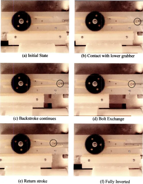
Figure 3-10 illustrates the interaction between the grabbers and the bolt during a single popper inversion cycle. To make the process easier to follow, the point of contact between the bolt and grabber(s) has been indicated by a circle. Figures 3-10 (a) and (f) represent the beginning and end, respectively, of the inversion cycle, at which points the bolt is not in contact with either grabber.
(b) Contact with lower grabber
(c) Backstroke continues (d) Bolt Exchange
(e) Return stroke (f) Fully Inverted
Figure 3-10 (a)-(f): Exchange of bolt during Popper Inversion (a) Initial State
3.3.2.2
Storage/Loading
In this model the storage enclosure for balls was moved to the interior of the blaster, contributing to a more compact design. A length of PVC tubing with a compression spring in the back was used to store up to 7 balls. This tube also served as the guide for the sliding pump used in the inversion process. An elbow joint at the front of the tube directed the balls into the firing position in front of the popper. This elbow joint could be rotated 900 to allow the balls to be loaded.
Figure 3-11: Visualization of balls in storage chamber
Loading of the balls happened simultaneously with inverting. As the bolt was pulled back out of the way, the first ball was pushed into the firing position by the spring in the back of the storage tube. Prior to inverting the popper, the secondary ball applied an upward force on the primary ball, pinning it against the bolt, as shown in Figure 3-12.
As the bolt was drawn back, it pulled the ball back slightly, coming to rest slightly behind where it began, but now centered in front of the popper. The secondary ball still provided some force on the primary ball, pushing it against the top wall of the firing area, and keeping it in the proper firing position. As the design team learned in the previous model, the primary ball could still be fired with sufficient velocity while being held in place by the secondary ball.
Figure 3-13: Foam ball in fully loaded position
3.3.2.3
Triggering
Triggering was again performed by hand for this model. A small force applied on the back of the bolt was sufficient to discharge the popper, as long as the bolt was pushed straight ahead. If the bolt was twisted or the force was not applied parallel to the motion of the racks, a much higher triggering force was required. This discovery helped to shape the development of a mechanical triggering mechanism in the next model.
3.3.3 Rapid Prototyped (RP) Model
This final model was an approximation to not only a "works-like" model but also a possible "looks-like" model. While retaining many of the mechanical elements integrated into the Metal Model, the RP Model also took on a sleeker, more finished shape. The body was fully enclosed, hiding all of the mechanical elements from the user. Hasbro provided the design for a commonly used handle, which was incorporated into the
model. The overall design of the blaster was reminiscent of a traditional shotgun, with the sliding pump, large firing barrel and trigger location.
This model was designed in SolidWorks and rapid prototyped by Hasbro using stereo lithography (SLA). A set of CAD drawings can be found in Appendix A.2.
Figure 3-14: Fully Assembled RP Model
3.3.3.1
Popper Inversion
The RP Model used the same mechanism for popper inversion as the Metal Model. Once again a rack and pinion system was used to invert the popper, with the main rack produced as a part of the top of the sliding pump. A new gear and set of racks was fabricated, but due to inaccuracies in the production of the parts, the same gears, and shorter versions of the same racks from the Metal Model were used.
A new problem that was encountered with this model was having the front gripping tooth on the grabber racks break off due to excessive stress on this single tooth. The actual source of the problem was hard to identify because the model could only be operated while it was completely assembled. This meant that the inner workings were fully enclosed, so the grabber (and the source of the problem) could not be seen.
One possible explanation for this problem was the poor meshing of the primary gear and the main rack. There was a very tight fit between the teeth of the primary gear and those of the main rack, meaning that the primary gear did not rotate smoothly as the pump was moved backward, instead often moving in short bursts and possibly causing the grabbing tooth to break.
Another problem was the roughness of the material used to produce the model. By design, the fit between the sliding pump and the storage barrel was tight; however, the friction between these pieces was larger than expected, requiring more force than anticipated to overcome this resistance. By sanding the outside surface of the storage barrel and the inside surface of the sliding pump, the friction was reduced by a small amount. The amount of sanding that could be performed was limited by the thickness of the walls of the model. If too much surface material was removed, the walls would have become too thin and might have cracked or broken.
A final step taken to combat the dry friction was the addition of Johnson's Baby Powder. This acted as a solid lubricant and allowed the pump to slide much more easily, in turn allowing the primary gear to rotate more smoothly. However, the baby powder had to be reapplied often to continue to be effective and was not a good long term solution.
3.3.3.2
Storage/Loading
The storage and loading aspects of this model were very similar to the previous model. The cylindrical storage chamber running from the back to the front of the blaster was long enough to store 6 balls, and housed a compression spring at its rear to push the balls out of the front of the chamber and into the firing position. A semi-spherical guide piece
was attached to the front of the spring to mimic the shape of a foam ball and to help push the balls forward through the elbow joint and into the firing position.
The elbow joint leading from the front of the storage chamber to the firing chamber was rotated 900 to allow for loading. To ensure that the elbow would not over-rotate in either direction, a small guide post was placed on the side of the joint. This post was designed to fit into a guide channel cut into the side of the blaster, which prevented the elbow joint from rotating beyond 900 and from going beyond the correct firing position.
(a)
(b)
Figure 3-16: Elbow Joint closed (a) and open (b) to allow loading
After the balls were loaded, the primary ball was lightly pinned between the secondary ball and the bolt extending out of the popper. When the popper was inverted, the bolt would draw the primary ball backwards and into the firing position, with the secondary ball pinning the primary ball against the roof of the firing chamber.
As the model was tested, two major factors were identified that sometimes combined to prevent the balls from reliably moving into the proper firing position. First, the unexpectedly high friction of the production material resisted the motion of the balls through the storage chamber and the elbow joint. Secondly, the inside diameter of the loading chamber and the elbow joint did not have sufficient clearance space for the balls.
Due to the high friction, the balls were unable to slide (translating without rotating) across the surface of the storage chamber as they were pushed forward by the spring, instead being forced to roll along the surface. This became a problem as the balls attempted to roll through the elbow joint. Because of the lack of extra clearance, one ball would sometime roll up the side of the ball in front of it, trapping both balls in the elbow.
The inside of the storage chamber and elbow was sanded extensively in an attempt to reduce the friction and provide more clearance, but this did not have any noticeable
effect. Baby powder was added inside the elbow to act as a solid lubricant and did result in improved performance, but had to be reapplied often.
After sanding failed to provide any noticeable improvement, the design team attempted to overcome these problems by increasing the force supplied by the spring. It was theorized that with more force, the balls might be successfully pushed through the elbow despite the high friction and tight clearance.
A spacer was placed behind the spring at the back of the storage chamber, which moved the spring forward. This increased the compression of the spring when the chamber was loaded, causing the spring to supply a greater force to the balls. However, this increased force failed to improve the performance. A second spacer was added, further increasing the force, but this also yielded the same results.
3.3.3.3
Triggering
This model included a mechanical trigger, located in the contoured handle, which was based on a common blaster handle design provided by Hasbro. This handle and the trigger can be seen in Figure 3-17.
Figure 3-17: Handle and Trigger
The trigger was located near the back of the blaster, in the same position it would occupy in a traditional shotgun. This traditional location, along with the familiar pump action, allowed the user to intuitively understand how to operate the Multi-Shot
PopperM. This instant familiarity was viewed as a benefit to any toy marketed to
children, who may lose interest in a toy that was extremely complicated to operate.
The triggering mechanism itself involved several components, as shown in Figure
3-18. These components were necessary to translate the force applied to the trigger at the
back of the blaster into a force on the popper at the front of the blaster.
Figure 3-18: Triggering Assembly
The part of the trigger visible to the user comprised only about one third of the entire trigger. The section of the trigger that was hidden had a raised key on one side, which fit into a keyway inside of the handle. This ensured that the trigger would move in only a single plane and would not twist or rotate.
The trigger was directly connected to the lower linkage, which was held in place by a pin through a hole in the middle of the linkage. Near the connection to the trigger, this linkage was attached to a fixed point in the blaster with a spring, so that after being displaced, both the linkage and trigger would return to their normal position. As the user pulled back on the trigger, the lower linkage would rotate about the pin. This rotation resulted in horizontal movement at the top of this linkage, which in turn translated into horizontal motion of the upper linkage attached to the top of the lower linkage.
This upper linkage was then connected to the "pusher", which was the final piece of the triggering assembly, and was the piece that actually made contact with the popper, causing it to invert and discharge the projectile. The pusher fit into a horizontal channel behind the racks and gears, which restricted its motion to a single plane, harnessing only the horizontal displacement of the upper linkage.
Figure 3-20 shows the location of the triggering assembly both before and after triggering occurs. In Figure 3-20(a) the popper inversion stage has been completed and the popper is ready to discharge a projectile. Figure 3-20(b) shows the triggering assembly after the trigger has been pulled back, and the stored energy of the popper has been discharged.
(b)
Figure 3-20: CAD Model displaying trigger assembly ready for triggering (a) and immediately after projectile has been discharged (b).
The head piece of the pusher was designed to contact the popper as close to its center as possible to keep the triggering force to a minimum, ensuring that the popper would discharge reliably. However, since this head piece was located directly behind the popper, it had to be designed to allow the bolt to pass through it freely. The first iteration of the head piece allowed the bolt to fit through it, but a problem arose during popper inversion.
As the bolt was pulled back by the grabbers, its vertical orientation remained fixed, but it would jostle horizontally from side to side a small amount. This side to side motion brought the bolt into contact with the sides of the head piece, and the threads on the bolt
would sometimes get caught on the head piece. The bolt would then become stuck and could not be pulled back by the grabber, preventing the popper from fully inverting. This was also another likely cause of the front tooth breaking off of the grabber during inversion - a problem cited above in the Popper Inversion section. By redesigning the head piece to allow for more side to side motion, and using smooth electrical tape to cover the rough metal edges where contact with the bolt would occur, as shown in Figure
3-21, this problem was solved.
(a) (b)
Figure 3-21: Initial (a) and refined (b) head piece of pusher
A final shortcoming of this trigger design was that there was very little safeguard
against unexpected discharge of projectiles. By its nature, the popper would be stable once it had been inverted, requiring some outside force to cause a projectile to discharge. However, it was possible that if the blaster was dropped or bumped against a rigid object, the jarring effect would cause the popper to return to its natural position and discharge a projectile unexpectedly. Due to the fragility of this model, the design team chose not to test this scenario extensively.
Chapter 4
Conclusion
4.1
Summary
The design team began this project with the goal of designing a safe and fun toy, which used Hopper Popper ActivationTM to fire multiple Nerfe foam balls. Through the product design process a series of iterative models were produced, from which the team was able to learn which concepts worked well and where problems were found, learning valuable lessons to be used as the design process progressed.
The final iteration of the Multi-Shot PopperTM had some functional limitations but was sufficient to illustrate that all of the key customer needs were likely to be satisfied by the proposed solutions. It was capable of storing 6 standard Nerf balls, used Hopper Popper ActivationTM as its discharge mechanism, was simple to operate, used pump action and took safety into account. While the final implementation of the loading system was not completely reliable, the design itself was shown to work in a previous model, and the popper inversion and triggering system both perform well.
The Multi-Shot PopperTM's ability to shoot multiple foam balls using Hopper Popper ActivationTM was something that no other toy could match. Additionally, it had a sleek appearance, was relatively compact, simple to operate, and used a fun pump-action style of motion. These features, along with its novelty, are intended to give the Multi-Shot PopperTM a unique place within its intended market.
4.2
Future Work
Future work on the Multi-Shot PopperTM could include implementing more stringent safety measures to prevent unexpected discharge of projectiles. In the retail version of the Nerfo Atom BlasterTM, a safety mechanism was implemented that locked the popper in place once it was inverted, and prevented it from being discharged unless a ball was properly seated in the firing position. This safety mechanism guarded against firing
improvised projectiles and might be a good candidate for use with the Multi-Shot PopperTM. The addition of a dry lubricant improved the reliability of the loading process in the final prototype, but a permanent solution should be pursued. Suggested solutions include increasing the diameter and/or decreasing the sharpness of the curve of the elbow joint, or using a different production material with lower friction. The trigger could be raised so that it is in line with the sliding pump, preventing a torque from being created around the handle as the user operates the toy. The loading procedure could be refined by adding a small catch at the end of the elbow joint to hold the balls in place as the elbow joint is rotated back to the firing position.
Appendix A
A.1 Hasbro Inc Corporate Quality Assurance Safety and Reliability
Specification [3]
HASBROINC.
CORPORATE QUAUWA5URANCE
SAFErY AND RElJAMITYSPECMICAfION
SRS-045
TIL.E PRWJECDLES
BY: C. FISCHER APPROVAL
DATE JUNE I, 1999 REVISION: G
1I. PURPOSE
To e•sabIht ecdeali ffr it
wus
umcael dwcatmidim alinoic pummsw tfpjedoil; aused n•dston•, Inod. T ek•mto Hm iys tmanpt •a•ypmliufijmy (eqmecil ep iy) tD clddmwi&e •i• e tal oplay vue •SI~Iig fptentedby pjedi Sm as tauclhae. but under o hmyueba oitiom of ure arn abuse, sa- ktl Cf r I the onfqiumim thMs edfziaudilo w m am ue ie tDg Obl mquiUmmS
for ectil
2.A SCOPE
This qxdc tia p1dis to bukh " A) tAt are ixoded to ntmah poyies mi e fligtby means of a Ai clz mcniuuuiauh khefkinei eungy athepojdisiu daumin by he toy and mt by the urmad B) caIic pjxtfle wthw t daimdudms. -a amsa am d dts iblamdedtobe
hmn, heiiqsfm, pmpek b•les, bows d amms an otr citmsn iSded to be rom but auiteukdettWbecaughOz
Thm sefucmbm does notSaUly to dij admpAuduin mmlxed to papel a gVunlbased vdmcuhr
toy alkmgack a M d ah mfa, nr whamn lr a pojecll is inuiko t a dilwu lmves the
dim•s meumia•n (eg& a Fpin • "llmachie)
PRjectiles wdihuudanut amUy acc .sqta u *l for oys wi& a zumiunumaage pSmet3 as .ind
Pjechl •e anly fr yswith a iia ag gae f4ys amlup)
Pmjeclilesamlsfande aoy a e aly for toa m uck w4a jmi agrade
of 5 ya.s miip.
Hfrlicce-type pjectles fiht we hudd f ticrldirlups us crly acceptle iftoysuita
mniumuanap Made of Syems mduly
3. DEFINITIONS
31 PIROJECILE WrH STORED ENERGY: m objectpmpeid by mmns f.a disdmapu.dnim cqable of mg dlekinugum=gyler the mudofflr openut
SRS-045 PAGE 2 OF 12 REVIS)N: G
3.2
fROJECMILE
WIBOUT STORED ENERGY An objecIn ,moEdyby eumgiq
Ied
byachid
3.3 DIEXSCHARGEMCHANISM: a iimae syum for rdleadng mlpupemlng pmojeils
3A4 PROJECILE TIP -Any pout ofa pjeilh- anm be epect s ad to cmiud
-mp sfe (r4ma ey5) dmi flight A tip w einding ed fa pzpjuexns no he
aondypasdip"e . Ondisc far lib puediles• fh "ed" affie disc scomdemd as
the tip. On wmk-type pjeciles that Ism a riXg 'hmal hepeimle, all exposed swfrac
of Le ring omd be mided •ip-.
Note Ik r11uia af 63 qlyb t allt
See Figuxe 2 fr a pital dqticm of e pM radii an a dic-type pwjewl
3-5 OECIW TIP. -a cammut tis aSldctoie iaitg emldfapjedlle unoimiiz ijy
ifit duklimw t a e body • alh o to pomt dmop to e pojes•an tu wgn, atilg a or
damtn imnikmte od4echt
3.6 RES•LIENT TIP: a tipa nimpct sf•p ca pwjetle tht has a Shein A dUmen$dEt gI.~I tmn
55 (as mufhld an the imnpact sfce offre tipL
3.7 REID PROJEC•ILES: pimElike it mimqct tip ham a dwue A dmense t is pgmuatilhm
55-31 PROJECTILE GUNS AND BOWS AND ARROWS: wehumd-ldlpjedii luhem Omt are
cmprmle in scrde I mal fmn oar bow mid anow. Fmrpmpnm to specificatim• mull
pmjecil
lamelms scald
Wthe
size oftoly figmes; (c&
Q1 Joe) we m
fpojecil
gad.
4.9. TEST EQUIPMENT
4-1 A dmar m ia le ofmeaing a mullmpjed ie(arpIm Had mlpKt gage) travdmigat a
high qed (e& 11 mihu).
412 HaIcm mpt cylinde (per SRS-001, figue2)
43 Lalmamy balm with m amxmcy of+/- 0 1 Vm. e. Sa1a0KSI).
4-4 A•im• aflzmyi it•miequ zms af 5c.2
4-5 A slel ball having a nmind diant of 15 mm mnd a mm of 14.00 +/- 0.05 gamus.
SRS-045
PAGE 3 OF 12
REVISION G
5.0 TEST ROCEDURE
5.1 KINETIC ENERGY DETIFERMINATION
5-1-1 Dukiutic uukjOmsD j)ofapjewtlk sidlI b .ddlulwlzgeymtir
=mgy = pojeV2)
v= ne masti mapmctie = OWK d. vvwbcyacftfrjmn*c~(nSW~)
Caovmim fidr. lMtuec =.447142 x niesthw
5.11 T anm ofpjecti ) l•lbe delmimbby-ii a simpqle an a mbamy blanc A affiedt mqple ice (at letot30) ajcuilles dhl be wuiglDb fna the amag uwet pIs 3
ad Ideim bis Dqapp lit weit i
Kgimsldfor Wm'
5i13 The xelcity ofapjedie (v) &&llbe ddmiidby iA a stl fuale didclpUe muecisofthe
taypumjedmdut ifutoftde mwkpn. RwIoigUmpIJ). he vdoity ofthepjeil d&lbe
calcledfiuUatheSpe
v(nsam Ju)=nphx.447142. hevalaf vin l equaiufmisthemm thy nfemauma
afagiumpqjectilk
51 Test fx Patti of Toy Pujedils wIh Stkr Emay
511 FMl
Frm aW llfatntimfai at ot ttuuty mles memig 105Immx 10 mm Enhmemht se
mple is Iee fuuatvi iy din i•ucig ames a is Tmmysk almm fifab Aida
uit wirfybe qulky affl. aukniam fmitt amls am Ieqimioklett the
by-512 Fad ilVifrain
a) Tle qu•ity afthe nidd be zried as tuloms:
b) Pbic e- athe smks offMibdwmte two 0-ing of
tfie
damp g fIe uaI day Ehe ibetwem the dnmp so ht th fal dingnis envlydy si•ms with oun arak.
c) ne fcm he Aiu e an a sdtuatily hmzialm•fe so tIhat de fI diqigm mabks m.
an* btas 15 dpes am 20 dgpes alim t he lmimal
PAGE 4 OF 12 REVISION: G
d) 1Pmim sedbd so ta hndtbal is inaed nthe it would fil fmely iugh a weical ~ of 3009 sio siDe the tami2n 25 adimmIst maft el• fuildi
e) Examie whetbr ar not tfe adi ~ mngntmd as i ec lin 52.3
0 Ifthe sladbal dos mt cmae me fiAd ihpn to mpirm np st*s b) to d) a dfam foir Itnes,
prauidfdi leachtimefie fril di&spm dnesmtnimne
g) IWal fin ofte fafd iioafrs do at n Iyae, upe gp b) to but thid s tim drop the steeld bad
xouzgh a lh)tof500uma
b) Iff the bcauses the f di~agm to rupmn as ~specifdin5.23, sept q b) t d) a fr
fourtimesnapoumieddAmt eh tetheafildiqdupmdnadosipqtI
5-23 hIrael•tim
¶1ufhidif mdmdpla Adbearmidmedasmatnupliffftheadllumwintidnuapfirmnim spiaw
hote. Ame d dt hl mt be canddmed as a ~me.
Te fildiujdxngme dalbecwusidued ay ad fibe hils aimK widnt mUntiftimin a qlit a hl.
Me D nafaliinagfcismplthht=1 tmbeiusedIaDtekt the toydabecmuiduadasnveifd as bing afa itable quaity if aw fie auxsilnfiat abjetdt tblhe dm dp ihe* f 50 mtu idipkhuahell
5a24 Test Spimaen
The toy mbnlmx d fr his test d be • •uttie ofthe mn paputim and dh im Ime be
subectd to any nnul me and resnbly fmumablem abuse tesA pir to peaeiatio tinag de ty.
5.2.5 Pocedume
The poedm n be cmild at in a cmlitiavinmmnt as flaw
a) Flace me .fthe t riUfiS SIamUpeS iwnteathe woa ipO Ef1 clqiIUD fmNe ad lmP the
fluaimg f chmp dsoa t the fil dhPp is evreytiord a m amscwridmkles
b) Place dufe Uam&piigne Iim s be ihfhd i&numlies k a suadbiiay retiyw pbla
c) LJad the pjectile inthfe fdiuge mIINi ian
SRS-O45
PAGE 5 OF 12
d) Paitim toyso ath
1) The d af tiy, irte ed aft pojctile a the ad aftisc di
liefavrjmpiubhst it 150E mnrathe •il•d ha•s mad
2) Wvetn t cti i ejeund t pek afe pjetie wolbe sbsnpialmy abmk
P
selzv sah ie Boh pe d 4 m. C peirep•jtile- ,-iczik k ~aoir•se•neres Fp•ibl
m t4 fae dipbo
TMe np
mt
sholl
sThe
thear attmoes the pjectdle romela the fi diagnan when the iy was
teandainamemdmxzee Aih51
53 pa~c Test Fr Pje*ciles
P*ojuelles d be popeled by mkir wel dcluPne medimmdn diutus i a Mcrdeiock wl (3
eqial) t sAfce) ocn st at a diqei 1 wt I 00 mo) ph &le ofthe pfjectile fnm he fmit
zd afte dmi11gem n twbicn Tee I&dhUp malian dhlU be nal pdapamdiulrby te wL 5t4 utsednaPbuEe TeuiFg
Mmhun alpaIionI
m
abunirn,
f a=
envammnzd keitig mnth pumetileper the rappupi.e
tedt
pln fr its punt posEct
53 IpoiLad Fnjetdile Test
DeaPjinueu i iII.ja ld ifp-btdigendpu imnchmin i afdistzS Mp . muhe ctilel a(tA the pjkelle s desmned foran wiQw aecificaa ten diPhngse m m Taesfudik avimed
pojectie d i" ke& bSt is n mied to, at he Molowing dabchur
SRS-045
PAGE 6 OF 12
REVISION G
(All asurements in inches)
A) ConectionPen Cp i
1) Penel Opaing Fluid Conecian Pen
Oil-Bsed Quick Dry
18 ml ZLC1-W
Manfacturre Pentel Ca. L~
Mald in Japan
B) Marker 1) Pa telMaker
F50
Made in Japan
Al) tDtglena~th-1.0l ches
m nihnnm diameaer- 0-7 inch ninimmian d rter- 53 inch
Dimensins
Bi) totallegh -33 iches
iameter- 091 inch
Ti~: lqng- 0.28; width-0.18 inch
Tip Body lngt& -070 inch
ma. diamener-0.65 inch
nIfL diameter-0.36 inch C) Marker Ca
1) Flurescemnt Cap
Zebra Pen 2 ThSin ize Cap
2) FhnScent Pn Cap Zebra Pen 2 Tbn Size Cap
3) Fibr p Pement Marker Cap
Asthie 70 HigihPermaue Xylene Free EK-70
Manubmit$ r Shaschita Prdrc Made in Japan
4) Fiber Tip PermAIent Mader Cap Attline 70 EhigPerforman Xylne Free EK-700
Mandue Sciht PrJduct
Made in
Japan
Cl) length -0.93 ich
max diamn er - 035 inch
mn diameter - 0.23 ich
C2) kleu - 1.82 inches
man. diamer - 0%58 inch mun dci eter -028 inch
C3) kBth- 1.71 inches
ma. diameter - 0.66 inch
mni dmeter- 0.51 inch
C4) evgth- 152 inches
rn diameter - 0.70 inch
am. diameter -0.69 inch
SRS-045 PAGE 7 OF 12 REVISION G 1) Tm Clip # Eleptmt Tihgal Art No. PM121 Made inhCina
DI) length -119 iwes man. diameter -037 inch
mi. diameer - 0.15
dietert ofwire -0.04 inch
E) Pen
1) Ball PenBody
Zebia -New Crystal
N-5000 MadeinJpan 2) BallPemBody Zebra -Had-Crystal N-5100 Madein Japan
3) Ball Pen Body
Bic #C-B-19
4) B Pen Cap
Zebra N-5000 MadeinJapm 5) Bald lniMtalNo~zle
Zebra - Hard Cys
N-5100
PnsReil
1) Bic #C-B-19
2) Zetn Badpoint Pen ReilBR-AiA-H-B
El) kng- 4S6 ines
mn diamneae- 032 inch
min dameter -0200 inch
E2) kogth-4.3 inches
mar diameter - 031 inch
min d -iner- 0.21 inch
E3) legth- 532 inich max dimmner -0.29 inch
miL diametr -0.24 inch
E4) length- 232 rches
ma. diameer - 0-47 inch
min diamter -0.25 inch
E) length- 0.46 inch
max. diamneer- 0.22 inch
mit diameer -0.13 inch
Dimni=ns
Fl) length- 5.17 irrh
nma diamener - 0.19 inch min diameer - 0.12 inch
K F2) length 5 48 iches max diameler- 0.12 inch
mim dimetr -0.09 ich
![Figure 3-1: Poppers in the Natural (a) and Inverted (b) States [1]](https://thumb-eu.123doks.com/thumbv2/123doknet/14678663.558680/20.918.201.716.491.672/figure-poppers-natural-inverted-b-states.webp)
![Figure 3-5: Popper Holder with (a) and without (b) Popper [1]](https://thumb-eu.123doks.com/thumbv2/123doknet/14678663.558680/22.918.203.718.790.1021/figure-popper-holder-b-popper.webp)