HAL Id: hal-03038312
https://hal.archives-ouvertes.fr/hal-03038312
Submitted on 3 Dec 2020HAL is a multi-disciplinary open access archive for the deposit and dissemination of sci-entific research documents, whether they are pub-lished or not. The documents may come from teaching and research institutions in France or abroad, or from public or private research centers.
L’archive ouverte pluridisciplinaire HAL, est destinée au dépôt et à la diffusion de documents scientifiques de niveau recherche, publiés ou non, émanant des établissements d’enseignement et de recherche français ou étrangers, des laboratoires publics ou privés.
High-Throughput Differentiation of Embryonic Stem
Cells into Cardiomyocytes with a Microfabricated
Magnetic Pattern and Cyclic Stimulation
Gaëtan Mary, Aurore van de Walle, Jose Efrain Perez, Tomofumi Ukai, Toru
Maekawa, Nathalie Luciani, Claire Wilhelm
To cite this version:
Gaëtan Mary, Aurore van de Walle, Jose Efrain Perez, Tomofumi Ukai, Toru Maekawa, et al.. High-Throughput Differentiation of Embryonic Stem Cells into Cardiomyocytes with a Microfabricated Magnetic Pattern and Cyclic Stimulation. Advanced Functional Materials, Wiley, 2020, 30 (25), pp.2002541. �10.1002/adfm.202002541�. �hal-03038312�
1
High-Throughput Differentiation of Embryonic Stem Cells into Cardiomyocytes with a
Microfabricated Magnetic Pattern and Cyclic Stimulation
Gaëtan Mary+, Aurore Van de Walle+, Jose Efrain Perez, Tomofumi Ukai, Toru Maekawa, Nathalie Luciani, Claire Wilhelm*
G. Mary, Dr. A. Van de Walle, Dr. J. E. Perez, Dr. N. Luciani, Prof. C. Wilhelm
Laboratoire Matière et Systèmes, Complexes MSC, UMR 7057, CNRS & University of Paris, 75205, Paris Cedex 13, France. + Equal contribution
E-mail: claire.wilhelm@univ-paris-diderot.fr
Dr. T. Ukai, Prof. T. Maekawa
Bio-Nano Electronics Research Centre, Toyo University, Kawagoe, 350-8585, Japan; Graduate School of Interdisciplinary New Science, Toyo University, Kawagoe 350-8585, Japan.
Keywords (5 maximum): magnetic nanoparticles; stem cell differentiation;
cardiomyogenesis; magnetic cell stimulation; microfabrication
Abstract
Pluripotent stem cells are central tools to many regenerative medicine strategies due to their ability to differentiate towards the three embryonic germ layers. One challenge remains in providing control over their differentiation into specific lineage, such as cardiac commitment. Here, the possibility of directing cardiomyogenesis of embryonic stem cells (ESCs) using a microfabricated magnetic pattern is demonstrated. The stem cells are labeled with magnetic nanoparticles, aggregated into embryoïd bodies (EBs) onto the pattern, and stimulated with a local magnetic force applied via the pattern. The EBs formed on this magnetic device
experience the same differentiation profile than the ones created by the common hanging drop approach, while it allows high-throughput production of hundreds of EBs. Further on/off cyclic magnetic force stimulation mediated by the same device is sufficient to enhance cardiomyogenesis in a way that almost all EBs develop spontaneous beating, confirmed by the overexpression of -actin and troponin proteins, and by the upregulation (2 to 5-fold) of genes involved in mesoderm differentiation (Nkx2.5, Gata4, and Gata6), and more
specifically cardiac lineage (Tnnt2, Myh6 and Myl-2). Beyond holding high application-level potential, this work confirms that physical forces, and specifically on/off dynamic ones can be sufficient to govern cell function.
2
1. Introduction
The production of in vitro three-dimensional multicellular assemblies, or spheroids, has been of recent interest for tissue engineering and regenerative cell therapies. It stands as a pivotal biological process to initiate the differentiation of stem cells into specific pathways, such as chondrogenesis or cardiomyogenesis. The most common spheroid formation techniques rely on well established procedures that include the aggregation of cells via their culture in suspension[1] or on non-adherent surfaces[2], their pelleting by centrifugation,[3] or their self-assembling by bioprinting.[4] In parallel, material and nanotechnological means have
advanced not only to control cell patterning but also to direct cell function such as stem cells differentiation, using for examples nanoparticles or nanoelectrodes,[5] or specific substrates,[6] combined or not with nanomaterials (e.g. nanoelectrodes, nanofibers, nanowires,
nanotopography, nanopillars)[7]. Among them, iron oxide nanoparticles have recently emerged as magnetic cellular label that has a double advantage. On one hand, it can be exploited to promote cell aggregation via localized magnetic forces and organize cells into engineered tissues.[8] As such, it has been employed for the formation of scaffold-free cell-spheroids[8b, 9], combined with standard techniques such as the hanging drop method[10] or agarose-well patterning,[11] and used as well to seed cells within 3D scaffolds.[12] On the other hand, it offers the possibility to control cell functions, including their differentiation.[13]
Spheroids based on embryonic stem cells (ESCs), termed embryoïd bodies (EBs), are particularly relevant as these cells can differentiate into lineages representative of the three embryonic germ layers and their EBs not only mimic early stages of embryonic development but also can be directed into specific organs due to their pluripotency. Despite most recent advances, it is still difficult to control the differentiation of pluripotent stem cells and maintain simultaneously a high production of differentiated or precursors cells, both being of particular relevance for application in regenerative medicine, such as in cardiac regeneration.[14] One emerging approach for cardiac repair, alternative to cardiac transplantation and implantable
3
mechanical-assisted devices in case of severe heart failure, is to transplant cells.[15] When stem cells (typically mesenchymal ones[16] or pluripotent ones[17]) were administered after myocardial infarction, cardiac performance was improved, but with low tissue integration and contraction generation.[18] Approaches have been tested to increase contraction, by aligning
cardiac cells using electrospun nanofibers[7b, 7c] or micropatterned surfaces,[19] or by orienting cells using soft lithography;[20] however, these approaches are two-dimensional, based on adult cardiac cells, with low output.
Iron oxide nanoparticles have recently provided a solution for the differentiation of ESCs as cardiomyocytes.[13d] Upon internalization of these magnetic nanoparticles into ESCs, the cells
were manipulated via magnetic forces to form three-dimensional EBs on a one-by-one basis, which were then stretched periodically using a magnetic attractor. This purely mechanical stimulation prompted the differentiation of the cells, reaching differentiation levels
challenging those achieved by the more traditional chemical stimulation. This initial study thus shed light on the potential of a magnetically-induced stimulation for cardiac regeneration. Yet, it could perform only on a single EB at a time, and could not provide translatable
conditions to produce clinically relevant numbers of functional cells.
Herein, a magnetic stimulation of EBs is accomplished as well, but at a high-throughput level thanks to the design of an original, high precision, all-integrated microfabricated pattern consisting of 900 magnetic microtips. This micro-pattern allows the controlled formation of 900 EBs in only one pipetting step and offers the possibility of a totally remote stimulation of said EBs, with no direct contact between the cells and the magnetic attractors. Remarkably, using this design, we demonstrate the directed cardiomyogenesis of ESCs upon remote
(electromagnetic) cyclic stimulation of ESCs labelled with magnetic nanoparticles, surpassing the cardiomyogenesis achieved in the previous study,[13d] and confirming the importance of
4
2. Results and Discussion
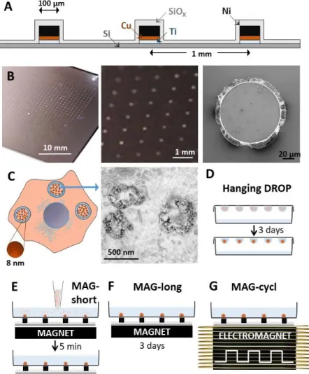
The photolithography-patterned nickel microtips device was fabricated to achieve a spatially controlled and highly localized magnetic attraction (Figure 1A and Figure S1). The end device accommodates 900 microtips, each 1 µm in height and 1 mm apart (Figure 1B). The magnetic characterization of the microtips is shown in Figure S2, providing a magnetization of 4x10⁵ A/m. The device is positioned upon a permanent magnet or an electromagnet, both developing a 0.2 T magnetic field perpendicular to the device substrate. The magnetic field concentration by each microtip was computed and is presented in Figure S3A. It results in a magnetic field gradient in the 100 T/m range 100 µm apart from the microtips surface (Figure S3B). Magnetic nanoparticles were internalized in the ESCs upon a 30 minutes incubation at [Fe]=2 mM, these same conditions having been previously reported as having no impact on ESC viability or differentiation profiles.[13d] After cellular uptake, the nanoparticles were localized in the cell endosomes (Figure 1C). Magnetically-labelled ESCs were then
organized into EBs either by the typical hanging drop method (Figure 1D), with EBs being formed over three days of drop confinement, or under a set of three conditions using the magnetic microtips pattern (Figure 1E-G). For all three conditions, a magnet was placed below the device to magnetize the tips and achieve localized cell attraction and EB formation. In the first case, the magnet was removed after five minutes (MAG-short, Figure 1E), whereas in the second one it was removed after three days (MAG-long, Figure 1F). In the last
condition, the magnet was maintained over the three first days, but was replaced with an electromagnet for 6 hours per day, imposing a cyclic magnetic field at a frequency of 1 Hz (MAG-cycl, Figure 1G). It should be stressed that the magnetic stimulation was applied during the first three days of EB formation and growth, when the differentiation pathways are setting up. Besides, in a more practical term, the cellular magnetic forces are significant only over the first cell divisions within the EBs.
5
EB formation (1000 ESCs per EB) is immediate when using the magnetic microtips, with cell aggregation taking place within seconds of seeding (Figure 2A). At day 3, the EBs were collected from the drops or from the magnetic pattern. All four tested conditions, the three magnetic ones and the hanging drop, were then transferred in non-adherent dishes and left to mature as spheroids for 2 more days. At day 5, the EBs were transferred to adherent tissue culture wells, and left there to finalize their differentiation pathway. Figure S4 summarizes all steps occurring upon the 10 days of ESCs differentiation, and presents the different analyses performed at various time points. EBs size was measured at days 0, 1, 3, and 5 (only 3 and 5 for the hanging drop condition). After 1 day of magnetic seeding (Figure 2B, 2G), no size difference was observed over the three magnetic conditions. At day 3 and day 5, EBs diameter were similar across all four conditions (including the hanging drop), at approximately 350 and 500 µm, respectively (Figure 2C-F, 2G). At day 7 and day 10, each EB was observed to record the occurrence of spontaneous beatings. The beating events can be seen on
supplementary Movie S1, for all conditions. Figure 2H-K shows representation illustrations of these beating events for each conditions, with spatio-temporal analysis (kymographs). If there is little or no cell displacement (i.e. beating), the position of the cells in the area selected on the images can be seen as unaltered over time, defined as straight lines along the time axis of the kymographs (vertical in Figures 2H-K); however, if beating takes place, it translates into regular perpendicular lines (at given time interval). The beating frequency was then systematically extracted from all kymographs, appears distributed in the 1-2 Hz range (Figure
2L), and is very similar across all the conditions, showing that there is no effect of EBs
magnetic formation and stimulation on the beating phenomenon itself, once triggered. Finally, the percentage of beating EBs was quantified across all conditions, at days 7 and 10 (Figure
2M). It is remarkably increased for the MAG-cycl condition, at both times, reaching 92% of
beating EBs at day 10, percentage rarely achieved even with the use of the most efficient chemical factors for cardiomyogenic differentiation induction of ESCs.[22]
6
The response of the EBs to the magnetic forces originates from the magnetic nanoparticles that are internalized and confined intracellularly, within endosomes. To explore the impact of the magnetic force at the magnetic endosome level, electron microscopy of EBs submitted to the magnetic field for 6 hours was performed and measurements were made alongside the direction of the magnetic field (Figure S5). It shows that the localisation of the magnetic endosomes is not impacted by the magnetic force. This is consistent with the value of the magnetic force generated on each endosome by the magnetic field gradient created by the nickel microtip, below 0.1 pN, negligible in comparison to active trafficking and cytoplasm viscous friction. Some endosomal cause for cardiomyogenesis cyclic activation is thus unlikely, and nanoparticles confined within endosomes should be seen as embedded in a viscoelastic matrix, simply providing the cell with a magnetic moment. The mechanical response from the cyclic stimulation is then generated at the EB scale. It is confirmed by direct visualisation of EB cyclic deformation (3-4 % range), shown in Figure S6, or on supplementary Movie S2.
The increase of cardiomyogenesis triggered by the cyclic magnetic stimulation was further confirmed by immunolabeling and gene expression. Two structural proteins located in the sarcomere were labeled with fluorescent antibody: α-actinin, typical of muscular cells, and cardiac troponin T, typically expressed in cardiomyocytes. Figures 3A and 3B show an impressive increase in both labels for the MAG-cycl condition, when compared to the three other conditions, which look similar. Additional analyses are shown in Figures S7-S8 ( -actinin; long and cycl conditions), and in Figures S9-S12 (troponin-T; MAG-short, MAG-long, MAG-cycl and DROP conditions) also presenting F-actin labeling with SiR-actin. All images corresponding to the MAG-cycl condition reveal a striated organization for both proteins, representative of the development of sarcomeres, necessary units for cell contraction. It was less marked for observations made at day 7 (Figure S13, MAG-cycl).
7
The expression of six genes characteristic of the endo/mesoderm (the transcription factor Gata6), and/or more specifically of the cardiac mesoderm (the transcription factors Gata4 and Nkx2.5, and regulating proteins directly specific to cardiac contraction troponin T (Tnnt2), α myosin heavy chain (Myh6), and myosin regulatory light chain 2 (Myl2)) was assessed at days 5, 7 and 10, and normalized to the same gene expression at day 0 (Figure 3C and Figure S14). It first evidences that differentiation of the ESCs toward the cardiac mesoderm takes place for the hanging drop control, with a time-dependent increase of all selected gene expression. This was expected as this technique has specifically been developed for allowing cardiac differentiation of ESCs through aggregation of the cells and their growth in a confined environment.[23] Results show that the EBs formed on the magnetic pattern with no further magnetic compaction (MAG-short) display a similar gene expression than the hanging drop method, sometimes very slightly downregulated, but never more that 1.5-fold. When magnetic compaction was applied all along the first days of differentiation initiation (MAG-long), mesoderm and cardiac mesoderm gene expression was sometimes slightly upregulated, but never more than 2-fold. By contrast, what was highly significant is the upregulation of all genes involved in cardiac differentiation when cells were cyclically stimulated (MAG-cycl), always in the range of a 2 to 5-fold increase.
An additional experiment was performed to confirm that the effect observed is not due to the application of a cyclic magnetic field only. To do so, EBs made of cells not labeled with the magnetic nanoparticles were formed via the hanging drop approach and subjected to the cyclic magnetic field at days 2 and 3. Gene expression analyzed at days 5, 7, and 10 is shown in Figure S15. It evidences no difference between EBs subjected or not to a cyclic magnetic field, and further indicates that the cyclic magnetic field alone is not sufficient to have an effect on the differentiation of ESCs. We also verified that the cyclic magnetic field was not triggering an increase in magnetic nanoparticles intracellular degradation. In this case EBs containing magnetically labeled cells and exposed or not to the cyclic stimulation were
8
measured by magnetometry. Results are displayed in Figure S16 and indicate a similar slowly decreasing rate of the EBs magnetic moments, demonstrating that the cyclic stimulation does not impact the fate of the nanoparticles inside the cells.
Finally, the cardiomyogenesis triggered here by cyclic electromagnetic stimulation should be compared to the proof of concept study exploring the role of a magnetically-induced
mechanical stimulation on EB.[13d] When observing the gene expression of proteins involved in cardiac contractility, such as troponin T (Tnnt2), myosin regulatory light chain 2 (Myl2), and α-myosin heavy chain (Myh6), an upregulation of 8, 4 and 2-fold is reached, respectively, when comparing the EBs stimulated by the magnetic pattern device to those stimulated in the previous stretching device. Therefore, not only the magnetic micro-pattern set-up allows for the production of thousands of EBs, but also it appears to streamline the cardiac
differentiation of ESCs.
3. Conclusion
The advent of microfabrication offered promising materials tools to engineer stem cells into matured cells such as cardiomyocytes depending on substrate topography or rigidity
variations.[24] Herein, a microfabricated magnetic pattern was specifically designed for the high-throughput production of EBs and enhanced cardiomyogenesis. Upon cell labeling with magnetic nanoparticles, 900 EBs could be magnetically formed in a single pipetting step, instead of one by one for the common hanging drop method. Without any further stimulation, these EBs have the same differentiation potential toward the mesodermal pathway than when formed by hanging drop in optimal conditions.
The even more unprecedented advantage of the magnetic pattern device resides in the possibility of further stimulating the EBs magnetically. When dynamic (cyclic), this stimulation drove the EBs towards cardiac differentiation with a remarkable efficiency.
9
Indeed, after 10 days, more than 90% of the EBs were beating, a much higher percentage than with the state-of-the-art hanging drop approach. Also, when comparing with previous studies that used growth factors to increase the differentiation, such as TGF and BMP2, the
cardiomyogenesis enhancement obtained here without any additive of any sort seems even more effective.[25] This remarkable result not only indicates applicative relevance of the magnetic device but also beautifully underlines the control that purely mechanical stimulation may have on the differentiation of stem cells.
In conclusion, the magnetic microtips pattern provides a high-throughput approach for EBs formation. It allows their remote mechanical cyclic stimulation, induced magnetically,
sufficient to direct almost totally ESCs differentiation towards the cardiac lineage. It could be considered as a next potent platform for high scale production of stem cells-derived
cardiomyocytes for regenerative medicine therapies.
4. Experimental Section
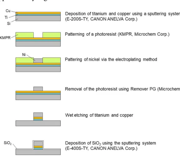
Magnetic pattern: Magnetic pattern was fabricated on a silicon substrate via electroplating
and UV photolithography. Titanium and copper films were formed on a silicon substrate using a sputtering system (E-200S-TY, CANON ANELVA Corp.) and reversal patterns of magnetic dots were obtained by a negative tone UV photoresist (KMPR, KAYAKU Advanced Materials, Inc.) via UV lithography. A nickel film was then deposited on the substrate via electroplating and the UV photoresist was removed by Remover PG (KAYAKU Advanced Materials, Inc.). The titanium and copper films were wet-etched and finally silicon oxide was deposited using the sputtering system. The pattern was magnetized by placing it over either a permanent neodymium magnet (50 mm x 50 mm x 20 mm) creating a 0.2 T magnetic field in the device plane, or over an electromagnet to generate an on/off magnetic field. The electromagnet was composed of a custom-made water-cooled coil (6Ω, 14 mH) wrapped around a soft iron polar piece (diameter 55mm, height 85mm). 4A-on/off current
10
(1Hz) was delivered to the coil using a TGA 1242 signal generator (Aim&TTi) and amplifier (Kebco BOP), creating an on/off 0.2 T magnetic field on the device.
ESCs and magnetic labeling: CGR8 mouse embryonic stem cell were purchased from Sigma
(07032901) and were cultured on 0.1% gelatin-coated surfaces in fresh GMEM medium (Sigma, G5154) supplemented with 10% fetal calf serum, 2 mM glutamine, 1% nonessential amino acids, 0.1 mM β-mercaptoethanol, 1 mM sodium pyruvate, 1% penicillin/streptomycin and 1000 U/ml of leukemia inhibitor factor (LIF, Thermo Fisher Scientific). They were passaged every 2 days at a density of 104 cells per cm², and were systematically used at passage 5 to 8 (passage zero being initial purchased batch). An older CGR8 cell line was also tested (Figure S14), corresponding to another cell batch, having experienced over 50
passages, and less competent for cardiomyogenesis. The magnetic nanoparticles used were made by aqueous co-precipitation of iron salts, they have a mean diameter of 8 nm, and a polydispersity index of 0.35, and are the most commonly used in biomedicine applications.
EBs formation and differentiation: At day 0, ESCs were labeled with the magnetic
nanoparticles (30 min, [Fe]=2mM), then detached and resuspended in differentiation medium (same as culture medium, but with 20% fetal calf serum and without LIF factor). EBs were next formed either by the hanging drop method (DROP, considered as control, seeding of 1000 ESCs in a 30 µL drop, plated on Petri dish cover gently turned over on the dish filled with PBS) or onto the magnetic pattern. ESCs (100 000) were then transferred to 12 mm diameter glass-bottom dishes, previously treated with PLL-PEG (SuSos) diluted in 10 mM HEPES (30min, 10 mg/ml) to prevent adhesion, and placed over the magnetic pattern device. Each dish covers 100 magnetic dots (1000 ESCs available per dot), and multiple dishes can be placed together on the device. The device is then placed over the permanent magnet, and the dishes are left on site for 5 min (MAG-short) or until day 3 (MAG-long). For the MAG-cycl condition, the device is placed on the electromagnet for on/off magnetic stimulation cycling at a 1 Hz frequency for 6 hours per day, the first 3 days. At day 3, all EBs (hanging drops and
11
magnetically formed ones) are collected and transferred to non-adhesive Petri dishes for 2 days for 2-days maturation before being individually seeded at day 5 in 0.1% gelatin-coated 24-well plates. Figure S2 illustrates the 10-days differentiation process.
Immunohistology: After paraformaldehyde (4% in PBS) fixation and Triton permeabilization
(15 min), cell samples were incubated sequentially with blocking solution (BSA 5%) for 1 hour at room temperature, primary antibodies overnight at 4°C (mouse monoclonal anti- -actinin, Sigma Aldrich, A7811, dilution 1:400; mouse monoclonal (IgG1) anti cardiac Troponin T, Thermofisher, MA5-12960, dilution 1:200), goat anti-mouse IgG secondary antibody for 2 hours at room temperature (Sigma-Aldrich, 43394, IgG-Atto550, dilution 1:500), and DAPI for 30 min at room temperature (Sigma-Aldrich, D9564, 1 µg/mL), and mounted (Fluoromount, Sigma Aldrich, F4680) on slides. Images were acquired with Olympus JX81/BX61 device/Yokogawa CSU device spinning-disk microscope (Andor Technology) using 60X oil objective (Olympus).
Relative quantification of gene expression by real-time PCR
Samples for PCR were harvested at day 5 (5 EBs per sample), day 7 (3 EBs per sample), and day 10 (2 EBs per sample). At least 4 independent samples were analyzed for each
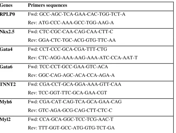
independent data point, and two independent experiments were performed (total of 8-10 samples per condition). Total RNA was isolated using the NucleoSpin RNA kit (Machery-Nagel). Complementary DNA (cDNA) was produced using the SuperScript II Reverse Transcriptase kit (Thermo Fisher Scientific) and random hexamers. Real-time quantitative PCR was conducted using the SYBR Green dye and the StepOnePlus detection system (Thermo Fisher Scientific). The expression of the housekeeping gene of the 60S acidic ribosomal protein P0 (RPLP0) was used as a reference transcript. All primer sequences are provided in Table S1.
Supporting Information
12
Acknowledgements
This work was supported by the European Union (ERC-2014-CoG project MaTissE #648779). We thank Aude Michel (Sorbonne Université, CNRS, PHENIX, UMR8234) for nanoparticles synthesis, Christine Péchoux from Mima2 platform-Inra (Jouy en Josas) for TEM analysis, and Myriam Reffay for discussion.
Received: ((will be filled in by the editorial staff)) Revised: ((will be filled in by the editorial staff)) Published online: ((will be filled in by the editorial staff))
13
Figure 1. Remote, magnetically actuated, mechanostimulation of ESCs using a
microfabricated (A) magnetic device. B) Image (left) of the 100 μm diameter microtips pattern composed of 30x30 magnetic nickel dots (900 in total); close-up image in the center showing the 1-mm spacing; and further magnification showing a single microtip observed by scanning electron microscopy. C) Magnetic nanoparticles (8 nm in diameter) are internalized in ESCs and localized within endosomes as illustrated on transmission electron microscopy image. D) Spheroids of ESCs are formed via the common hanging drop method (DROP). E-G) Spheroids of ESCs are formed by seeding the cells in a dish positioned on top of the microtips-device exposed to a magnetic field (magnet or electromagnet under the device). ESCs are attracted to the magnetic microtips and form cohesive 3D embryoid bodies (EBs). These EBs are then stimulated magnetically following three independent protocols: the
spheroids are either compacted magnetically E) for a short time-period (5 min; MAG-short) or F) for a long one (3 days; MAG-long) by keeping the permanent magnet under the device, or again G) the spheroids were cyclically stimulated using an electromagnet (3 days; MAG-cycl).
14
Figure 2. EBs magnetic stimulation. A-B) Images of EBs on the magnetic patterns 5 min (A)
or 1 day (B; MAG-cycl) after seeding. C-F) Representative EBs images for all seeding approaches, 5 days after EBs formation (day 5). G) Average size of all EBs for the four seeding protocols. H-K) 10 days after seeding (day 10), representative videos of 6 seconds analyzed using Image J, for the four conditions. In each image two defined beating areas (white, full lines) were selected for kymograph analysis (top and bottom raw) which displays the cells beating. M) Average frequency of the beating cells for all conditions, analyzed at day 10. L) Average percentage of beating EBs, at day 7 and day 10. Statistically significant
15
Figure 3. Magneto-mechanical stimulation induced positive expression of the structural
proteins A) mesoderm α‐actinin and B) cardiac troponin‐T. Immunofluorescence images of the specific antibodies (red) are merged with Dapi (green) for nuclei localization. C) Gene expression of proteins involved in mesoderm and cardiac mesoderm differentiation, and in cardiac progenitors, always renormalized by the expression of the same gene at day 0.
0 200 400 600 800 1000 1200 0 1 2 3 4 5 6 7 8 9 10 ** *** * ** 0 10 20 30 40 50 60 0 1 2 3 4 5 6 7 8 9 10 0 20 40 60 80 100 0 1 2 3 4 5 6 7 8 9 10 0 50 100 150 0 1 2 3 4 5 6 7 8 9 10 0 20 40 60 80 0 1 2 3 4 5 6 7 8 9 10 0 100 200 300 400 500 600 0 1 2 3 4 5 6 7 8 9 10 ****** *** ** * ****** *** ** *** ** *** * *** *** *** *** * Nkx2.5 Gata4 Gata6 Tnnt2 Myh6 Myl-2 G en e ex p ress io n 200 µm A-actinin C Day 10 (DROP) Day 10 (MAG-cycl) Day 10 (MAG-long) Day 10 (MAG-short) 20 µm B Troponin 200 µm Day 10 (DROP) Day 10 (MAG-cycl) Day 10 (MAG-long) Day 10 (MAG-short) 50 µm G en e exp res si o n G en e ex p ress io n G en e exp res si o n G en e exp res si o n G en e ex p ress io n
Days Days Days
Days Days Days
DROP MAG-cycl
MAG-long MAG-short
16
Statistically significant differences are shown as compared to control (DROP), with *p<0.1, **p<0.05, ***p<0.01.
Table of contents entry
Using a pattern of magnetic microtips and magnetically-labeled embryonic stem cells, high-throughput cell aggregation into embryoid bodies can be achieved. The magnetic pattern allows an on/off magneto-mechanical stimulation of the stem cells which impressively enhances their differentiation into cardiomyocytes when compared to a conventional hanging drop method, with over 90% of embryoid bodies developing spontaneous beating.
Keyword: Magnetic-Induced Stem Cells Differentiation
G. Mary, A. Van de Walle, J. E. Perez, T. Ukai, T. Maekawa, N. Luciani, C. Wilhelm* Title: High-Throughput Differentiation of Embryonic Stem Cells into Cardiomyocytes
with a Microfabricated Magnetic Pattern and Cyclic Stimulation
ToC figure (55 mm broad × 50 mm high)
ELECTROMAGNET
EMBRYOID BODIES
MAGNETIC MICROPATTERNS
17
References
[1] J. M. Kelm, N. E. Timmins, C. J. Brown, M. Fussenegger, L. K. Nielsen, Biotechnology and bioengineering 2003, 83, 173.
[2] J. M. Yuhas, A. P. Li, A. O. Martinez, A. J. Ladman, Cancer research 1977, 37, 3639. [3] B. Johnstone, T. M. Hering, A. I. Caplan, V. M. Goldberg, J. U. Yoo, Experimental
cell research 1998, 238, 265.
[4] a) A. Ovsianikov, A. Khademhosseini, V. Mironov, Trends in biotechnology 2018, 36, 348; b) G. Forgacs, K. Jakab, A. Neagu, V. Mironov, Google Patents, 2015; c) L. Moroni, T. Boland, J. A. Burdick, C. De Maria, B. Derby, G. Forgacs, J. Groll, Q. Li, J. Malda, V. A. Mironov, Trends in biotechnology 2018, 36, 384.
[5] a) H. Rabie, Y. Zhang, N. Pasquale, M. J. Lagos, P. E. Batson, K. B. Lee, Advanced Materials 2019, 31, 1806991; b) T. H. Kim, C. H. Yea, S. T. D. Chueng, P. T. T. Yin, B. Conley, K. Dardir, Y. Pak, G. Y. Jung, J. W. Choi, K. B. Lee, Advanced Materials
2015, 27, 6356.
[6] a) F. A. Pennacchio, C. Fedele, S. De Martino, S. Cavalli, R. Vecchione, P. A. Netti, ACS applied materials & interfaces 2017, 10, 91; b) M. Mahmoudi, S. Bonakdar, M. A. Shokrgozar, H. Aghaverdi, R. Hartmann, A. Pick, G. Witte, W. J. Parak, ACS nano
2013, 7, 8379; c) O. Mashinchian, L.-A. Turner, M. J. Dalby, S. Laurent, M. A.
Shokrgozar, S. Bonakdar, M. Imani, M. Mahmoudi, Nanomedicine 2015, 10, 829; d) S. Bonakdar, M. Mahmoudi, L. Montazeri, M. Taghipoor, A. Bertsch, M. A.
Shokrgozar, S. Sharifi, M. Majidi, O. Mashinchian, M. Hamrang Sekachaei, P. Zolfaghari, P. Renaud, ACS applied materials & interfaces 2016, 8, 13777.
[7] a) J. H. Lee, H. K. Choi, L. Yang, S. T. D. Chueng, J. W. Choi, K. B. Lee, Advanced Materials 2018, 30, 1802762; b) M. Kitsara, O. Agbulut, D. Kontziampasis, Y. Chen, P. Menasché, Acta biomaterialia 2017, 48, 20; c) G. Jin, R. He, B. Sha, W. Li, H. Qing, R. Teng, F. Xu, Materials Science and Engineering: C 2018, 92, 995; d) J. E. Perez, T. Ravasi, J. Kosel, Nanotechnology 2016, 28, 055703; e) C. H. Rasmussen, P. M. Reynolds, D. R. Petersen, M. Hansson, R. M. McMeeking, M. Dufva, N.
Gadegaard, Advanced Functional Materials 2016, 26, 815; f) X. Zhang, X. Cui, D. Wang, S. Wang, Z. Liu, G. Zhao, Y. Zhang, Z. Li, Z. L. Wang, L. Li, Advanced Functional Materials 2019, 29, 1900372.
[8] a) S. Hughes, J. Dobson, A. J. El Haj, Journal of biomechanics 2007, 40, S96; b) D. Fayol, G. Frasca, C. Le Visage, F. Gazeau, N. Luciani, C. Wilhelm, Advanced Materials 2013, 25, 2611; c) J. R. Henstock, H. Markides, H. Bin, A. J. El Haj, J. Dobson, in Nanomagnetic Actuation in Biomedicine, CRC Press 2018, p. 205; d) J. P. Armstrong, M. M. Stevens, Trends in biotechnology 2019; e) B. Son, J. A. Kim, S. Cho, G.-J. Jeong, B. S. Kim, N. S. Hwang, T. H. Park, ACS Biomaterials Science & Engineering 2017, 3, 1719.
[9] G. R. Souza, J. R. Molina, R. M. Raphael, M. G. Ozawa, D. J. Stark, C. S. Levin, L. F. Bronk, J. S. Ananta, J. Mandelin, M.-M. Georgescu, Nature nanotechnology 2010, 5, 291.
[10] a) V. H. Ho, K. H. Müller, A. Barcza, R. Chen, N. K. Slater, Biomaterials 2010, 31, 3095; b) R.-Z. Lin, W.-C. Chu, C.-C. Chiang, C.-H. Lai, H.-Y. Chang, Tissue Engineering Part C: Methods 2008, 14, 197; c) B. Mattix, T. R. Olsen, Y. Gu, M. Casco, A. Herbst, D. T. Simionescu, R. P. Visconti, K. G. Kornev, F. Alexis, Acta biomaterialia 2014, 10, 623.
[11] B. R. Whatley, X. Li, N. Zhang, X. Wen, Journal of biomedical materials research Part A 2014, 102, 1537.
[12] K. Shimizu, A. Ito, H. Honda, Journal of bioscience and bioengineering 2007, 104, 171.
18
[13] a) A. Tay, D. Di Carlo, Nano letters 2017, 17, 886; b) P. Tseng, J. W. Judy, D. Di Carlo, Nature methods 2012, 9, 1113; c) D. Liße, C. Monzel, C. Vicario, J. Manzi, I. Maurin, M. Coppey, J. Piehler, M. Dahan, Advanced Materials 2017, 29, 1700189; d) V. Du, N. Luciani, S. Richard, G. Mary, C. Gay, F. Mazuel, M. Reffay, P. Menasche, O. Agbulut, C. Wilhelm, Nature communications 2017, 8, 400; e) M. Ishii, R. Shibata, Y. Numaguchi, T. Kito, H. Suzuki, K. Shimizu, A. Ito, H. Honda, T. Murohara, Arteriosclerosis, thrombosis, and vascular biology 2011, 31, 2210; f) T. Norizadeh-Abbariki, O. Mashinchian, M. A. Shokrgozar, N. Haghighipour, T. Sen, M.
Mahmoudi, Journal of Biomaterials and Tissue Engineering 2014, 4, 579; g) B. Son, H. D. Kim, M. Kim, J. A. Kim, J. Lee, H. Shin, N. S. Hwang, T. H. Park, Advanced healthcare materials 2015, 4, 1339.
[14] M. Mahmoudi, M. Yu, V. Serpooshan, J. C. Wu, R. Langer, R. T. Lee, J. M. Karp, O. C. Farokhzad, Nature nanotechnology 2017, 12, 845.
[15] a) J. Tang, J. Wang, K. Huang, Y. Ye, T. Su, L. Qiao, M. T. Hensley, T. G. Caranasos, J. Zhang, Z. Gu, Science advances 2018, 4, eaat9365; b) H. Hamdi, V. Planat-Benard, A. Bel, E. Puymirat, R. Geha, L. Pidial, H. Nematalla, V. Bellamy, P. Bouaziz, S. Peyrard, Cardiovascular research 2011, 91, 483.
[16] a) M. Cai, R. Shen, L. Song, M. Lu, J. Wang, S. Zhao, Y. Tang, X. Meng, Z. Li, Z.-X. He, Scientific reports 2016, 6, 28250; b) A. D. Celiz, J. G. Smith, A. K. Patel, A. L. Hook, D. Rajamohan, V. T. George, L. Flatt, M. J. Patel, V. C. Epa, T. Singh, Advanced materials 2015, 27, 4006; c) K. Cheng, D. Shen, M. T. Hensley, R.
Middleton, B. Sun, W. Liu, G. De Couto, E. Marbán, Nature Communications 2014, 5, 4880; d) A. W. Heldman, D. L. DiFede, J. E. Fishman, J. P. Zambrano, B. H. Trachtenberg, V. Karantalis, M. Mushtaq, A. R. Williams, V. Y. Suncion, I. K. McNiece, Jama 2014, 311, 62.
[17] P. Menasché, V. Vanneaux, A. Hagège, A. Bel, B. Cholley, I. Cacciapuoti, A. Parouchev, N. Benhamouda, G. Tachdjian, L. Tosca, European heart journal 2015, 36, 2011.
[18] G. Vunjak-Novakovic, N. Tandon, A. Godier, R. Maidhof, A. Marsano, T. P. Martens, M. Radisic, Tissue Engineering Part B: Reviews 2009, 16, 169.
[19] M. R. Salick, B. N. Napiwocki, J. Sha, G. T. Knight, S. A. Chindhy, T. J. Kamp, R. S. Ashton, W. C. Crone, Biomaterials 2014, 35, 4454.
[20] W. Bian, B. Liau, N. Badie, N. Bursac, Nature protocols 2009, 4, 1522.
[21] a) C. L. Happe, A. J. Engler, Circulation research 2016, 118, 296; b) V. Panzetta, S. Fusco, P. A. Netti, Proceedings of the National Academy of Sciences 2019, 116, 22004.
[22] a) J. Li, M. Stouffs, L. Serrander, B. Banfi, E. Bettiol, Y. Charnay, K. Steger, K.-H. Krause, M. E. Jaconi, Molecular biology of the cell 2006, 17, 3978; b) P. W. Burridge, G. Keller, J. D. Gold, J. C. Wu, Cell stem cell 2012, 10, 16; c) P. W. Burridge, S. Thompson, M. A. Millrod, S. Weinberg, X. Yuan, A. Peters, V. Mahairaki, V. E. Koliatsos, L. Tung, E. T. Zambidis, PloS one 2011, 6, e18293.
[23] M. Pucéat, Methods 2008, 45, 168.
[24] a) A. J. Ribeiro, Y.-S. Ang, J.-D. Fu, R. N. Rivas, T. M. Mohamed, G. C. Higgs, D. Srivastava, B. L. Pruitt, Proceedings of the National Academy of Sciences 2015, 112, 12705; b) P. P. Abadi, J. C. Garbern, S. Behzadi, M. J. Hill, J. S. Tresback, T.
Heydari, M. R. Ejtehadi, N. Ahmed, E. Copley, H. Aghaverdi, Advanced Functional Materials 2018, 28.
[25] A. Behfar, L. V. Zingman, D. M. Hodgson, J.-M. Rauzier, G. C. Kane, A. Terzic, M. Pucéat, The FASEB Journal 2002, 16, 1558.
19
Copyright WILEY-VCH Verlag GmbH & Co. KGaA, 69469 Weinheim, Germany, 2018.
Supporting Information
High-Throughput Differentiation of Embryonic Stem Cells into Cardiomyocytes with a
Microfabricated Magnetic Pattern and Cyclic Stimulation
Gaëtan Mary+, Aurore Van de Walle+, Jose Efrain Perez, Tomofumi Ukai, Toru Maekawa, Nathalie Luciani, Claire Wilhelm*
G. Mary, Dr. A. Van de Walle, Dr. J. E. Perez, Dr. N. Luciani, Prof. C. Wilhelm ; Laboratoire Matière et Systèmes, Complexes MSC, UMR 7057, CNRS & University of Paris, 75205, Paris Cedex 13, France. + Equal contribution *claire.wilhelm@univ-paris-diderot.fr Dr. T. Ukai, Prof. T. Maekawa; Bio-Nano Electronics Research Centre, Toyo University, Kawagoe, 350-8585, Japan; Graduate School of Interdisciplinary New Science, Toyo University, Kawagoe 350-8585, Japan.
Supplementary Table
Genes Primers sequences
RPLP0 Fwd: GCC-AGC-TCA-GAA-CAC-TGG-TCT-A Rev: ATG-CCC-AAA-GCC-TGG-AAG-A Nkx2.5 Fwd: CTC-CGC-CAA-CAG-CAA-CTT-C Rev: GGA-CTC-TGC-ACG-GTG-TTC-AA Gata4 Fwd: CCT-CCC-GCA-CGA-TTT-CTG Rev: CTC-AGG-AAA-AAG-AAA-ATC-CCA-AAT-T Gata6 Fwd: TCC-CCT-GCC-GAA-GTC-ACA Rev: GGC-CAG-AGC-ACA-CCA-AGA-A TNNT2 Fwd: CGA-CCT-GCA-GGA-AAA-GTT-CAA Rev: TCC-GGT-TTC-GCA-GAA-CGT Myh6 Fwd: CGA-CAT-CAG-TCA-GCA-GAA-CAG Rev: GTC-AGA-GCG-CAG-CTT-CTC-C Myl2 Fwd: CCA-GCA-GGC-TCC-TCG-AAC-T Rev: TTT-GGT-GCC-ATG-GTG-TCT-GA
Table S1: Primers sequences used in real-time PCR analysis (5’ to 3’) for: 60S acidic ribosomal protein P0 (RPLP0), NK2 Homeobox 5 (Nkx2.5), GATA Binding Protein 4 (Gata4), GATA Binding Protein 6 (Gata6), Troponin T Type 2 (Cardiac) (TNNT2), Myosin Heavy Chain 6 (Myh6), Myosin Light Chain 2 (Myl2).
20
Supplementary Figures
Figure S1: Fabrication procedure of the nickel micropatterns covered with a silica layer using
a photolithography method.
Figure S2: Magnetization curve of 10 microtips obtained by means of VSM. The magnetic
moment of 10 microtips extracted from the magnetic pattern was measured, and the magnetization at saturation Ms (> 10000 Oe) was obtained, being of 57 μemu per microtip (= 57.10-9 A.m2). Knowing that each microtip has a volume V of 141372 µm3 (disc with a diameter
of 100 µm and height of 18 µm), the volumetric magnetization at saturation (Ms/V) of 4.105 A/m was retrieved.
21
Figure S3: Simulation of the magnetic field density (B, in Tesla) surrounding the microtip. It
was computed with COMSOL Multiphysics, upon the constitutive equations between B and H within the nickel microtip: B = μoH+B0 and B = μoH+M, where B0 = 0.2 T is the magnetic
field created by the magnet or electromagnet (perpendicular to the substrate), and M = 4.105 A/m is the nickel magnetization. The magnetic field is shown color-coded (A), and the magnetic field gradient (B) was extracted along the microtip axis. It is in the 100 T/m range 100 µm apart from the microtip surface (corresponding to the cell seeding plane, separated from the surface by a 100 µm thin glass slide).
0.1 0.2 0.3 0.4 0.5 0.6
Magnetic flux density B (T)
0 100 200 300 400 500 600 50 100 150 200 250 gr ad B ( T/ m ) Distance to microtip (µm) A B
22
Figure S4: Schematic of the methods employed for the differentiation of embryonic stem
cells toward the cardiac lineage (top raws) and of some typical genes expressed over the steps of this differentiation (bottom raws).[1-4]
[1] U. Rutishauser, J. P. Thiery, R. Brackenbury, B. A. Sela, G. M. Edelman, Proc. Natl. Acad. Sci. U.S.A. 1976, 73, 577.
[2] E. Willems, P. J. Bushway, M. Mercola, Pediatr Cardiol 2009, 30, 635.
[3] M. Nakanishi, A. Kurisaki, Y. Hayashi, M. Warashina, S. Ishiura, M. Kusuda-Furue, M. Asashima, FASEB J. 2009, 23, 114.
23
Figure S5: Impact of magnetic field application on intracellular localization of endosomes
filled with magnetic nanoparticles (magnetic endosomes). Embryoïd bodies (EBs) were either kept upon magnetic field for 6-hours (left), corresponding to the duration of the magnetic stimulation or just formed above magnet for 5-min, and then left free without any force application (right). A: Scheme illustrating the EBs either on magnet or left free, with a focus
24
at the cell level to define the two distances measured for magnetic endosomes localization: the distance of each endosome from the membrane at the magnet side (down on the scheme and images), and from the nucleus center (or the cell center if the nucleus is not visible on the observed section). B: Transmission electron microscopy (TEM) images of 70-nm thin
sections cut alongside the direction of the magnetic field. Magnetic endosomes clearly appear as dark organelles, filled up with the nanoparticles appearing as black dots because they are dense to electrons. Magnetic endosomes are found distributed within the cytoplasm, and in some cases, they are aligned one to the other (see bottom images) due to dipole-dipole magnetic force, 100 higher than the magnetic force created by the external magnetic field gradient. C: Transmission electron microscopy images without magnetic field application, featuring again the dark magnetic endosomes within the cytoplasm. D-G: Histograms of the distances of all imaged magnetic endosomes to the cell edge, upon magnet application (D) or without (E), or to the cell center, upon magnet application (F) or without (G). It demonstrates that the magnetic endosomes are still distributed all around the cytoplasm upon magnet application, evidencing that the magnetic force created on each endosome is not sufficient to displace them towards the side of the cells towards the microtips, and therefore no forces are exerted inside the cells at the cell membrane during magnetic stimulation.
Figure S6: Evidence of the mechanical deformation of the magnetic EBs upon cyclic magnetic
stimulation at 1 Hz. The images below represent the kymograph obtained in the centre of each EB (yellow line), and demonstrate a cyclic deformation of the EBs (3.5±0.9 %) following the 1 Hz frequency of the applied magnetic field.
25
Figure S7: Immunofluorescent analysis of -actinin for the condition MAG-long, at day 10. Additional images to the ones showed in Figure 3A. Cells were labeled with -actinin mouse monoclonal antibody, then stained using goat anti-mouse IgG secondary antibody (red, bottom panel) and counterstained with DAPI (blue, middle panel). Top panel is the merged image.
26
Figure S8: Immunofluorescent analysis of -actinin for the condition MAG-cycl, at day 10. Additional images to the ones showed in Figure 3A. Cells were labeled with -actinin mouse monoclonal antibody, then stained using goat anti-mouse IgG secondary antibody (red, bottom panel) and counterstained with DAPI (blue, middle panel). Top panel is the merged image.
27
Figure S9: Immunofluorescent analysis of cardiac troponin-T for the condition MAG-short,
at day 10. Cells were labeled with cardiac troponin-T mouse monoclonal antibody, then stained using goat anti-mouse IgG secondary antibody (red, second middle panel) and counterstained with DAPI (blue, first middle panel). SiR-actin probe was used (SC001, Spirochrome, 1:1000 in PBS for 2h at room temperature, before DAPI staining) to stain F-actin (yellow, bottom panel). Top panel is the merged image.
28
Figure S10: Immunofluorescent analysis of cardiac troponin-T for the condition MAG-long,
at day 10. Cells were labeled with cardiac troponin-T mouse monoclonal antibody, stained using goat anti-mouse IgG secondary antibody (red, second middle panel), then stained with SiR-actin probe (yellow, bottom panel) and counterstained with DAPI (blue, first middle panel). Top panel is the merged image.
29
Figure S11: Immunofluorescent analysis of cardiac troponin-T for the condition MAG-cycl,
at day 10. Cells were labeled with cardiac troponin-T mouse monoclonal antibody, stained using goat anti-mouse IgG secondary antibody (red, second middle panel), then stained with SiR-actin probe (yellow, bottom panel) and counterstained with DAPI (blue, first middle panel). Top panel is the merged image. In the middle raw image corresponding to the Troponin staining, four sections have been zoomed in and are displayed in the right column, showing the appearance of striated structures.
30
Figure S12: Immunofluorescent analysis of cardiac troponin-T for the condition hanging
DROP, at day 10. Cells were labeled with cardiac troponin-T mouse monoclonal antibody, stained using goat anti-mouse IgG secondary antibody (red, second middle panel), then stained with SiR-actin probe (yellow, bottom panel) and counterstained with DAPI (blue, first middle panel). Top panel is the merged image.
31
Figure S13: Immunofluorescent analysis of cardiac troponin-T for the condition MAG-cycl,
at day 7. Cells were labeled with cardiac troponin-T mouse monoclonal antibody, stained using goat anti-mouse IgG secondary antibody (red, second middle panel), then stained with SiR-actin probe (yellow, bottom panel) and counterstained with DAPI (blue, first middle panel). Top panel is the merged image. As compared to the same condition, at day 10 (previous Figure S11), the troponin staining shows less marked striated muscle fiber localization.
32
Figure S14: Use of another batch of CGR8 ESCs, having experienced a large number of
passages (over 50) prior to use. As shown in A), where the number of beating EBs observed at day 7 and day 10 are plotted for each condition, they were less competent to
cardiomyogenesis than the batch newly purchased (Sigma, 07032901) and used in the work. Indeed, less than 20% EBs were beating at day 10 for the control hanging drop condition, as well as for the magnetically patterned EBs without stimulation (MAG-short), while with the new batch, this percent was in the 40% range for both control and MAG-short conditions. Yet, the on/off mechanical cyclic stimulation (MAG-cycl) was again improving greatly cardiomyogenesis, with a more than 2-fold increase in the number of beating EBs at day 10. The positive impact of the cyclic stimulation to direct differentiation was further confirmed with RT-PCR, as shown in B). The mesoderm genes (NKX2.5, Gata4 and Gata6) and cardiac mesoderm Tnnt2 gene were 6 to 10-fold upregulated for the MAG-cycl condition. Note that the level of Tnnt2 expression is much lower than the one reached with the new CGR8 ESCs (see Figure 3C), confirming that this ESC batch was less competent for differentiation to the cardiac lineage. However, these results remarkably evidence that, for two independent ESCs batches used, the cyclic stimulation direct cardiomyogenesis, demonstrating further the robustness of the method.
33
Figure S15: Gene expression of EBs not labeled with magnetic nanoparticles and stimulated,
or not, with a cyclic magnetic field. EBs were formed via the hanging drop method starting with 1000 control (non labeled) cells, and were cultured for 2 days to allow the formation of a cohesive structure. At days 2 and 3, the “stimulated” EBs were subjected to the cyclic electromagnetic field, for 6 hours per day, while the “control” EBs were kept free of any magnetic field. Expression of genes involved in mesoderm differentiation (Nkx2.5, Gata4, Gata6 and Tnnt2) was analyzed at days 5, 7, 10 and expressed relatively to day 0. Results show that there is no difference in gene expression between EBs subjected or not to a cyclic magnetic field when no magnetic nanoparticles are internalized in the cells, indicating that a cyclic magnetic field alone is not sufficient to have an effect on the differentiation of ESCs towards the cardiac lineage.
Figure S16: Magnetometry performed at the EB level after their formation, over time (day 1 to
day 5). Herein, the EBs were prepared by magnetic attraction of the cells for 5 min (30 000 cells were used per EB to be in a range measurable by magnetometry). They were then left free after formation (condition MAG-short) or kept upon magnet and stimulated for 6-hours per day during the first two days (condition MAG-cycl). Parts a and b show typical magnetization curves for control (A) or stimulated (B) EBs obtained by placing 3 EBs within cuvettes that were measured via vibrating sample magnetometry, at 300 K. Part C shows the average of the saturation magnetic moment per EB, including over 4 independent measurements (with different EBs). It shows that the nanoparticles slowly degrade within the ESCs, but that the cyclic magnetic stimulation doesn’t change the degradation rate.
34
Supplementary Experimental Section
Transmission Electron Microscopy (TEM):The embryoïd bodies were fixed in 5% glutaraldehyde diluted in 0.1 M cacodylate buffer for 1 hour at room temperature, and then washed two times before storing them in 0.1 M cacodylate buffer. They were then contrasted with Oolong Tea Extract (OTE) 0.5% in 0.1 M Na cacodylate buffer, post-fixed with 1% osmium tetroxide containing 1.5% potassium cyanoferrate, gradually dehydrated in ethanol (30% to 100%) and gradually embedded in epoxy resins. Note that epoxy inclusion was achieved by maintaining the direction of the magnet in the vertical direction. Ultrathin sectioning (70 nm) was then performed, in the direction of the magnetic field for the ones placed upon magnet, sections were collected onto 200 mesh copper grids and observed with a Hitachi HT 7700 TEM operated at 80 kV. Sample preparation and observations were performed by Christine Péchoux at the facility of MIMA2 MET – GABI, INRA, Agroparistech, 78352 Jouy-en-Josas, France.
Magnetometry of EBs:
EBs were fixed at different maturation times and measured by magnetometry using a PPMS device equipped with a vibrating sample magnetometer (VSM) option (Quantum Design). The analysis was performed at 300 K and provided the magnetic moment of the EBs (expressed in emu) as a function of the applied field (between 0 and 20 000 Oe). The diamagnetic contribution of the cells and substrate, which appears as a negative slope over the saturation region, was then removed, and the magnetization at saturation was obtained.