CoMo: a Whiteboard that Converses about Code
by
Andrew Thomas Correa Sabisch
Submitted to the Department of Electrical Engineering and Computer
Science
in partial fulfillment of the requirements for the degree of
Doctor of Science in Computer Science
at the
MASSACHUSETTS INSTITUTE OF TECHNOLOGY
September 2014
c
Massachusetts Institute of Technology 2014. All rights reserved.
Author . . . .
Department of Electrical Engineering and Computer Science
August 8, 2014
Certified by . . . .
Randall Davis
Professor
Thesis Supervisor
Accepted by . . . .
Professor Leslie A. Kolodziejski
Chair of the Committee on Graduate Students
CoMo: a Whiteboard that Converses about Code
by
Andrew Thomas Correa Sabisch
Submitted to the Department of Electrical Engineering and Computer Science on August 8, 2014, in partial fulfillment of the
requirements for the degree of Doctor of Science in Computer Science
Abstract
Software engineers routinely solve problems by brainstorming at whiteboards. Among other modes, they communicate with speech and sketch. Unfortunately, the white-board plays the role of a passive medium. It serves only as a place to draw. But what if it could engage in the conversation, even to a limited degree? Ideally it would help guide the engineers to a solution by being an active participant in the conversation.
This thesis presents an early version of that vision: CoMo, a whiteboard that converses about code. CoMo is capable of engaging its user in a constrained mixed-initiative symmetric-multimodal conversation about a data structure manipulation. When it understands the data structure, it uses a code synthesis system to generate functioning C code. It can successfully hold a limited conversation and synthesize code for 50 manipulations on 8 data structures. This thesis further presents findings from an observational user study that helped guide the interaction with CoMo. Fi-nally, this thesis presents the mixed-initiative code-generation framework that CoMo implements to achieve its interaction, and the insights about having limited natural conversations about data structure manipulations that were gleaned while creating the framework.
Thesis Supervisor: Randall Davis Title: Professor
Acknowledgments
Finishing this thesis was the most difficult thing I have yet accomplished. There are many reasons for this, not least among which is that it is the first time in my life there was no clear goal; I needed to define one and bring it to fruition myself. I want to thank everyone that helped me through this, because this thesis was too great an undertaking for me to have accomplished without their love, support, understanding, play, and general ability to put up with me for the hardest 3 years. Thank you all.
Firstly I thank my adviser, Randall Davis. I have learned so much while under his wing that I am sure will help me through the rest of my life. Among his plethora gifts, I am most appreciative of my newly improved ability to manage projects and more clearly express ideas. Thank you Randy. This experience has been invaluable. I would not be the person I am today without you.
Most importantly, I thank my wife, Ashley. She calmed me down during the hard times and helped me up during the harder ones. She took care of me: feeding me, bathing me (I’m sorry that was required sometimes), and pointing out when I was being self-destructive in the most gentle way possible. Without her love and support I would not have been able to finish. Thank you, lar. You’re the lar. You cray. I love you.
I thank Ali Mohammad for being an understanding ear, always ready with good advice and a calm perspective. I supported him through the difficult final stages of his thesis and, given all the help he gave back, I believe that he remembers (and feels responsible for) giving even more support back. He edited my thesis, talked me through difficult problems, reminded me of the bigger picture, and apologized profusely for not doing more. Thanks Ali. You’re a great friend that I’m lucky to have been given the oportunity to become so close with.
I thank Asma Al-Rawi (or, as she’s known on the streets, Em). She helped me through some of the more emotionally challenging times. Whether it was by helping me think through my issues over an IM chat, a phone call, or in person, she always managed to calm me down by pointing out that one piece of information I just couldn’t
see. Due to her vast experience helping doctoral candidates finish their theses (and probably through her stories of woe that nearly always trumped mine in severity), she always managed to talk me off of the metaphorical ledge. Thank you, Em.
I thank Jonathan Eastep. He always had a way of remininding me of the good life: life after school when money would not be an issue anymore and I could leave my work at work. He gave me perspective that helped immeasurably. He focused me on the goal and even bought me dinner when he visited. Really, he was an all-around awesome friend. Thank you Jonathan.
I thank Marek Doniec. He is, without question, the best worst influence I have ever had the privaledge to know. He helped me relax at the end of hard days and easy days alike, and was a readily available gym buddy. As if that weren’t enough, he also helped me practice my German. Thank you Marek.
I thank all the memebers of the Multimodal Understanding Group: especially Jeremy Scott and Ying Yin. As academic siblings, we were in a uniqe position of being able to understand one another and help one another with research projects and academic life. Thank you all.
I thank the Agile Robotics group, and especially Seth Teller. Next to my adviser, Seth had the greatest influence on how I think about and perform research, and about how to manage large projects. Thank you AR, and thank you, Seth. I only wish you were here to read this.
I thank all my remaining friends and family, especially my brother, my mother, my father, and my uncle. They grounded me by reminding me of my roots, consoled me with their love, and lifted my spirits with their presence. Thank you all. I love you all.
Finally, I thank the broader CSAIL community, especially the members of TIG and the CSC. They made this place fun. Without them, I would not have wanted to come into work every day. I will never forget this time in my life, and I’ll always have wonderful memories thanks to them. Thank you all.
This work was supported by DARPA grant #N66001-10-2-4089, “CANDOR: Clean-Slate System Integrity using Selective Redo” and NSF grant #IIS-1018055, “Enabling and Exploring Natural Systems.”
Contents
1 Introduction 18
1.1 CoMo: the Code Monkey . . . 19
1.2 A Linked List Reversal . . . 22
1.3 Code Synthesis . . . 26
1.4 Interaction . . . 28
1.5 Contributions . . . 30
2 Related Work 31 3 Observational User Study 36 3.1 Participants . . . 36 3.2 Procedure . . . 38 3.2.1 Instruction Sheets . . . 39 3.3 Hypotheses . . . 41 3.4 Limitations . . . 42 3.5 Results . . . 43 3.5.1 Analysis . . . 43 3.6 Architectural Implications . . . 49 3.6.1 Remembering Names . . . 50
3.6.2 First-Pass Geometry Heuristic . . . 50
3.6.3 Input and Output States . . . 50
4 CoMo: an Overview 53
4.1 Basis on the User Study Findings . . . 53
4.2 The User Interface . . . 54
4.3 Linked List Find Last . . . 56
4.3.1 Initiating the Discussion . . . 56
4.3.2 Continuing the Discussion . . . 59
4.3.3 Synthesis & Verification . . . 63
4.3.4 Labeling the Data Structure and Manipulation . . . 69
4.4 Additional Functionality . . . 69
4.4.1 A More Educated CoMo . . . 69
4.4.2 Labeling Pointers . . . 69
4.4.3 Constraints . . . 70
4.4.4 Multiple Pointers . . . 70
4.5 Summary . . . 71
5 CoMo: Functionality 73 5.1 Mixed-Initiative Code-Generation Framework . . . 73
5.2 The Storyboard Programming Tool . . . 75
5.2.1 Programming with Examples . . . 75
5.2.2 An Example SPT Run-Through . . . 75
5.2.3 SPT Limitations & Ramifications for CoMo . . . 79
5.2.4 Summary . . . 83
5.3 Linked List Find-Last . . . 83
5.3.1 Describing the Data Structure . . . 83
5.3.2 Asking an Example Question . . . 86
5.3.3 Nonsensical Questions . . . 88
5.3.4 Remaining Questions . . . 90
5.3.5 Code Synthesis & Verification . . . 92
5.3.6 Labeling the Interaction . . . 99
5.4.1 System Architecture . . . 100 5.4.2 Interface Transition . . . 102 5.4.3 Sketch Recognition . . . 105 5.4.4 Speech Recognition . . . 108 5.4.5 Speech Generation . . . 110 5.4.6 Question Generation . . . 111
5.5 Assumptions, Algorithms, and Heuristics . . . 113
5.5.1 Parsing a Data Structure . . . 114
5.5.2 Abstracting the CFG . . . 116
5.5.3 Heuristics . . . 117
5.5.4 Abstractions . . . 121
5.6 Limitations . . . 122
5.6.1 AVL Tree Insertion . . . 123
5.6.2 Min-Heap Pop . . . 126 5.7 Conclusions . . . 129 6 Domain 131 6.1 Summary of Structures . . . 131 6.2 Similarity Classes . . . 133 6.3 Stack Push . . . 136 6.4 Queue Dequeue . . . 141
6.5 Singly Linked List Reversal . . . 146
6.6 Singly Linked List Find Last . . . 149
6.7 Singly Linked List Delete . . . 152
6.8 Ordered Doubly Linked List Insertion . . . 158
6.9 Binary Tree Left Rotation . . . 165
7 Contributions & Future Work 172 7.1 Future Work . . . 176
7.1.1 Recursion . . . 176
7.1.3 Specifying Algorithms . . . 177 7.1.4 Handling Multiple Large Structures . . . 178 7.1.5 Joint Synthesis Work . . . 179
List of Figures
1-1 Describing a linked list to CoMo. . . 23 1-2 The next question CoMo asks is about a list with four nodes. . . 23 1-3 The next two questions CoMo asks are about the list with one node
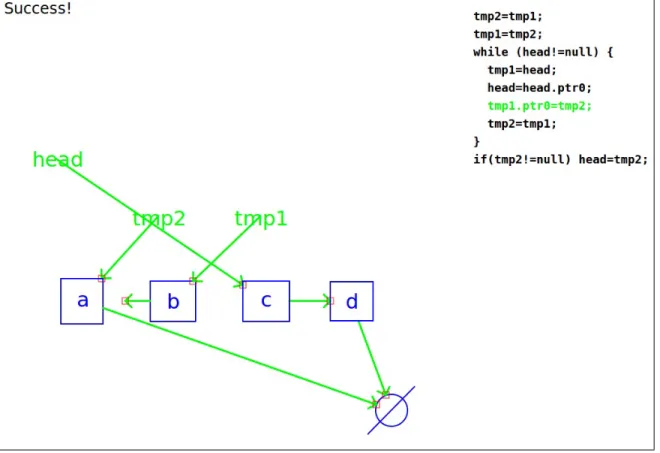
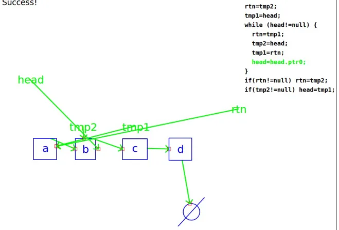
and the empty list. . . 24 1-4 CoMo animates the code’s execution on a structure. The line “tmp1.ptr0=tmp2”
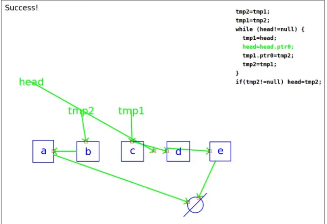
(highlighted in green) has almost completed its animation; the pointer attached to b has almost completed its movement from the c node to the a node. . . 25 1-5 CoMo animates the code’s execution on a new structure. The line
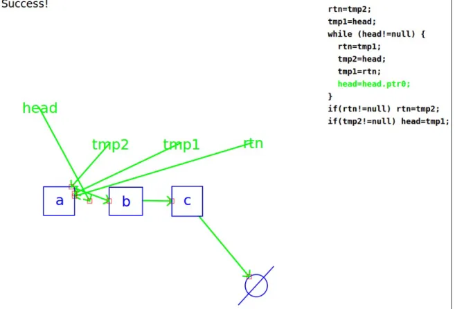
“head=head.ptr0” is in the middle of being animated; the head pointer is half way through its transition between that c and d nodes. . . 26
3-1 Exercises teachers were asked to give students. . . 38 3-2 Reminders presented to subjects in order to encourage a rich
interac-tion. These were placed on the front sheet of subjects’ instructions. . 40 3-3 Sample visual data structure vocabularies presented to subjects. . . . 41 3-4 The time it took each session’s descriptions and their sum. . . 43 3-5 Subjects’ responses to qualitative questions on a 5-point Likert scale.
Average responses are displayed between minimum and maximum val-ues. Note that the manipulation names were abbreviated to fit in the figure; subjects were presented with unabbreviated text. . . 45 3-6 Examples of the vocabularies used in the first session. . . 47 3-7 An immediately understood visual shorthand. . . 48
4-1 CoMo’s User Interface . . . 54
4-2 CoMo’s Interface: Populated . . . 55
4-3 The user draws a general list. . . 56
4-4 CoMo questions how to inductively define the ellipsis. . . 56
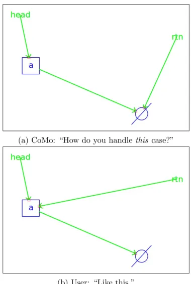
4-5 An automatically generated list with four nodes that CoMo uses to ask its first question: “How do you handle this case?” . . . 57
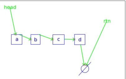
4-6 The user adds the rtn pointer to make this first state reflect how the manipulation begins. . . 57
4-7 The user demonstrates the manipulation and says, “Like this.” . . . . 58
4-8 CoMo: “How do you handle this case?” User: “That does not make sense.” . . . 61
4-9 CoMo: “How do you handle this case?” User: “That does not make sense.” . . . 61
4-10 CoMo: “How do you handle this case?” User: “That does not make sense.” . . . 61
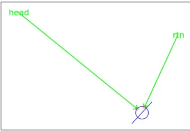
4-11 A question and the corresponding answer about a list with one node. 62 4-12 A question and the corresponding answer about an empty list. CoMo: “How do you handle this case?” User: “Do nothing.” . . . 63
4-13 CoMo animates the code on the initial example with four nodes. . . . 64
4-14 CoMo generates a structure with five nodes and animates the code. . 65
4-15 CoMo animates the new code on the same structure. . . 66
4-16 CoMo animates the new code on the list with four nodes. . . 67
4-17 CoMo generates a structure with three nodes and animates the code. 68 4-18 A doubly linked list general structure definition. . . 71
5-1 A linked list with four nodes and the same list reversed. . . 76
5-2 Linked lists that look the same reversed. . . 76
5-3 Example SPT input corresponding to linked list reversal. . . 77
5-4 Information SPT is able to infer from its input. . . 78
5-6 A shortened CFG and the resulting code. . . 79 5-7 The user draws a general list. . . 84 5-8 The question and answer about the inductive definition of the ellipsis. 84 5-9 The first questions (Fig. 5-9a) that CoMo asks and the user’s response
(Fig. 5-9b). . . 87 5-10 CoMo: “How do you handle this case?” User: “That doesn’t make
sense.” . . . 89 5-11 CoMo: “How do you handle this case?” User: “That doesn’t make
sense.” . . . 89 5-12 CoMo: “How do you handle this case?” User: “That doesn’t make
sense.” . . . 90 5-13 The question and answer about a list with one node. . . 91 5-14 A question and the corresponding answer about an empty list. CoMo:
“How do you handle this case?” User: “Do nothing.” . . . 92 5-15 The input CoMo produces for SPT. . . 93 5-16 The default CFG used by CoMo. §5.5.2 explains how this was selected
and how it can be altered. . . 93 5-17 SPT’s output before and after CoMo removes dead code. . . 94 5-18 This sketch is missing tmp1 and tmp2. . . 95 5-19 CoMo adds tmp1 and tmp2, initializes them to null, and resets the
structure to its starting state in preparation for code animation. . . . 96 5-20 CoMo animates the code on the initial example with four nodes. . . . 97 5-21 The augmented input CoMo produces for SPT. . . 98 5-22 SPT’s output before and after CoMo removes dead code. . . 99 5-23 An overview of CoMo’s architecture. Input is displayed at the top and
output at the bottom. . . 101 5-24 The state transition diagram describing how CoMo reacts to user input.103 5-25 A list with four nodes and a constraint showing it is ordered. . . 107 5-26 The subtrees of CoMo’s grammar corresponding to labeling and
5-27 Question about the list being less than the node to insert. . . 111
5-28 Question about the list being greater than the node to insert. . . 112
5-29 Subset of input to SPT illustrating constraint specification. . . 112
5-30 A binary tree. . . 114
5-31 A doubly linked list and extra node. The list is classified as the “main” structure, and the extra node as an auxiliary structure. . . 115
5-32 A doubly linked list. . . 115
5-33 A binary tree repetition definition. CoMo parses four options. . . 116
5-34 The CFGs used to synthesize code for an ordered, doubly linked list insertion. . . 117
5-35 The code synthesized for an ordered, doubly linked list insertion. . . . 118
5-36 An example AVL tree. . . 123
5-37 An AVL tree insertion consisting of a BST insertion followed by a rotation. . . 124
5-38 A snapshot of a possible interaction with CoMo about an AVL tree insert. CoMo has just performed a BST insertion, and the user is explaining why a rotation is required. . . 126
5-39 An example min-heap. . . 126
5-40 The process of popping an element from a heap; the minimum element is returned, and the next smallest is placed at the top of the heap, ready for the next pop operation. . . 127
5-41 A snapshot of a user explaining a min-heap pop manipulation to CoMo. Here, the user explains why a swap must happen. . . 128
5-42 The ability to move nodes’ positions allows the user to clean up the sketch. This figure differs from Fig. 5-41b only in the positions of the nodes. . . 129
6-1 A stack push and a linked list prepend. Note that these two manipu-lations are nearly identical. . . 133
6-2 List reversals for an ordered, doubly linked list and unordered singly linked list. Note that the operations required for the singly linked list reversal are a strict subset of the operations required for ordered, doubly linked list reversal. . . 134 6-3 The general stack and ellipsis definition . . . 136 6-4 A question and answer about pushing onto a stack with four nodes. . 137 6-5 The questions and corresponding answers about stacks with nothing
to add. These questions proceed identically to one another. . . 138 6-6 Question and answer about what to do with a stack containing one
node and an add pointer pointing at a separate node. . . 139 6-7 Question and answer about what to do with an empty stack and an
add pointer pointing at a node. . . 139 6-8 The input CoMo generates for SPT. . . 140 6-9 The raw and cleaned synthesized code for the stack push manipulation. 140 6-10 The definition of a general queue. . . 141 6-11 A question and corresponding answer about a queue with four nodes. 142 6-12 CoMo: “How do you handle this case?” User: “That does not make
sense.” . . . 142 6-13 CoMo: “How do you handle this case?” User: “That does not make
sense.” . . . 143 6-14 CoMo: “How do you handle this case?” User: “That does not make
sense.” . . . 143 6-15 CoMo asks about a queue with one element and an rtn pointer pointing
at null. . . 144 6-16 The question and answer for an empty queue. CoMo asks, “How do
you handle this case?” and the user responds, “Do nothing.” . . . 145 6-17 The input CoMo generates for SPT. . . 145 6-18 The raw and cleaned synthesized code for the dequeue manipulation. 146 6-19 The inductive definition of a general list. . . 146 6-20 A question about a list with four nodes. . . 147
6-21 Two questions about lists that look the same reversed. . . 148
6-22 The input CoMo generates for SPT. . . 148
6-23 The raw and cleaned synthesized code for the reversal. . . 149
6-24 CoMo recalls what a linked list is when asked. . . 149
6-25 The first question and corresponding answer that CoMo asks. . . 150
6-26 CoMo: “How do you handle this case?” User: “That does not make sense.” . . . 151
6-27 CoMo: “How do you handle this case?” User: “That does not make sense.” . . . 151
6-28 CoMo: “How do you handle this case?” User: “That does not make sense.” . . . 152
6-29 CoMo asks about a list with one node and rtn pointer pointing at null. 153 6-30 CoMo: “How do you handle this case?” User: “Do nothing.” . . . 153
6-31 The input to SPT generated from the find-last interaction. . . 154
6-32 The raw and cleaned synthesized code for the find-last manipulation. 154 6-33 CoMo recalls what a linked list is when asked. . . 155
6-34 CoMo asks a question about a singly-linked list with four nodes. . . . 155
6-35 CoMo asks a question about a singly-linked list with one node. . . 156
6-36 CoMo: “How do you handle this case?” User: “Do nothing.” . . . 156
6-37 The user decides to give two more demonstrations on structures with five nodes. . . 157
6-38 The input to SPT produced by CoMo. . . 158
6-39 The raw and cleaned synthesized code for the delete manipulation. . . 159
6-40 The inductive definition of a general linked list. . . 159
6-41 CoMo’s first question (and the corresponding answer) about a list with four nodes. . . 160
6-42 CoMo asks about how to insert a node into a list with one node when the node to insert is less than the node in the list. . . 161
6-43 CoMo asks about how to insert a node into a list with one node when the node to insert is greater than the node in the list. . . 162
6-44 CoMo asks how to insert a node into an empty list, and the user responds.163
6-45 CoMo: “How do you handle this case?” User: “Do nothing.” . . . 163
6-46 CoMo: “How do you handle this case?” User: “Do nothing.” . . . 164
6-47 CoMo: “How do you handle this case?” User: “Do nothing.” . . . 164
6-48 CoMo’s first try at producing SPT input. After one hour, CoMo halts SPT and retries. . . 166
6-49 CoMo’s second try at running SPT. This produces code after anywhere from 15 minutes to 2 hours. . . 167
6-50 The code produced after the second try. . . 168
6-51 The inductive definition of a general binary tree. . . 169
6-52 CoMo asks a question about a tree with four nodes. . . 169
6-53 CoMo asks two questions about trees that do not have enough nodes to be rotated. . . 170
6-54 The input to SPT produced by CoMo. . . 171
6-55 The raw and cleaned synthesized code for the left rotation. . . 171
7-1 A singly linked list append. Notice that the auxiliary structure (be-ginning with add) has more than one node. . . 178
7-2 An ordered, singly linked list insertion and an altered CFG that may work for it. Neither of CoMo’s CFGs are sufficient to perform this manipulation, however using this CFG may result in SPT synthesizing correct code. . . 179
List of Tables
3.1 Participants’ Demographic Information . . . 37
5.1 CoMo’s visual vocabulary. . . 106
5.2 List of phrases CoMo understands. . . 108
5.3 Things CoMo is capable of saying. . . 110
6.1 The list-like data structure manipulations about which CoMo can in-teract, separated by similarity. “LL” and “DLL” stand for “Linked List” and “Doubly Linked List” respectively. . . 135
Chapter 1
Introduction
Software engineers routinely discuss problems at whiteboards to find solutions, engag-ing in a multimodal dialog, primarily speakengag-ing and drawengag-ing. Both of these modalities have their advantages and disadvantages: drawing is visual and intuitive while speak-ing is succinct and rich. At the whiteboard, drawspeak-ing serves two purposes. It helps engineers visualize the problem and break it down into solvable sub-problems, and presents the problem in a more abstract, human-understandable form. Though draw-ing is a powerful tool, it has its limitations. Some thdraw-ings are more easily, quickly, and succinctly expressed with speech. For example, responding to some questions by simply saying “Yes” or “No” can be quicker and more natural than any other means. Together, these modalities can create a rich interaction full of potentially useful technical information.
Imagine the whiteboard actively participating in technical conversations of these kinds. It could engage in the conversation with the engineers by speaking, drawing, and asking questions, thereby helping the engineers come up with solutions more quickly. A smart whiteboard system of this kind has the potential to help engineers by guiding them through the problem-solving process, potentially avoiding common mistakes, and asking leading questions, e.g., about corner cases. Once a solution has been found, the system could help with the implementation process by generating code. Even if it can only generate simple code, a system like this has the potential to be a great help to software engineers.
This thesis presents an early version of that vision: a smart whiteboard system, called CoMo, that engages in a conversation-like interaction with a user involving speech and sketch about a data structure manipulation. Once the interaction is com-plete, CoMo uses a code synthesis tool to generate code implementing the discussed manipulation, then CoMo helps the user test the code by animating it on a drawn structure. This system has the potential to be used by students to better understand how code works by watching it animated on concrete, drawn structures. CoMo is a code generation tool that improves upon using state of the art code synthesis systems alone. This thesis gives example interaction with CoMo, describes an observational user study that guided the design of CoMo’s interaction’s structure, and details how CoMo works.
1.1
CoMo: the Code Monkey
I implemented CoMo, a smart whiteboard system able to hold a limited conversation involving speech and sketch concerning a wide range of different manipulations on a variety of different data structures. CoMo’s name has two meanings. It is both an abbreviation of “Code Monkey” and the Spanish word for “how,” used to ask someone to repeat what they said. (In English we use “what.”) It is a “code monkey” because it demonstrates its understanding of a conversation by synthesizing C code and animating it on concrete examples, both those the user drew and those that they asked CoMo to draw for them. As far as I am aware, CoMo is the first mixed-initiative, symmetric-multimodal, conversation-to-code smart whiteboard system.
CoMo engages in a mixed-initiative, symmetric-multimodal interaction, that is modeled after human-human conversations1. The interaction is multimodal in that it involves both speech and sketch. The interaction is symmetric because both modes of input are also modes of output: CoMo both interprets speech and sketch and speaks and draws to ask questions. It is a mixed-initiative system because either CoMo
1Since the interaction is strongly constrained, the words “converse” and “conversation” are used
sparingly in this thesis. They are used only to frame CoMo in the broader goal of participating as an engineer in the kinds of technical discussions mentioned above.
or the user can initiate an interaction. The user initiates interactions by drawing concrete examples of data structure manipulations, while CoMo initiates interactions by asking questions about concrete examples it draws.
Interactions with CoMo proceed in the five basic phases (Chapter 5 describes these in full):
1. The user initiates the interaction by:
• asking CoMo if it knows what a specific data structure or manipulation is; or
• demonstrating a concrete example on a drawn structure; or
• defining the general data structure to talk about.
2. CoMo asks questions (and interprets answers) about:
• an inductive general structure definition;
• a structure with four, one, and zero nodes; or—if the manipulation consists of two structures: a main and an auxiliary one—the power set of compar-isons between the main structure with four, one, and zero nodes and the auxiliary structure with one and zero nodes; and
• if the manipulation is on an ordered structure that (as above) involves multiple structures (e.g., an ordered linked list insertion)—the power set of constraint comparisons between single-node structures where the main structure’s node is less than and greater than the auxiliary structure’s node.
3. CoMo uses SPT [28] to synthesize code by:
(a) generating input based on examples the user drew;
(b) selecting a control flow graph (CFG) to use;
(c) running SPT; and
4. CoMo animates the synthesized code on examples until the user is satisfied it is correct.
5. If the code is incorrect, CoMo reruns synthesis (step 3) with new corrected examples.
Using these phases, CoMo is able to have an interaction with and generate code for a user about 50 manipulations on 8 structures. These structures and manipulations are listed here:
1. Stack (a) push (b) pop (c) poll 2. Queue (a) enqueue (b) dequeue (c) peek
3. Singly Linked List
(a) insert (b) delete (c) reverse (d) append (e) prepend (f) remove first (g) remove last (h) find first
(i) find last
4. Doubly Linked List
(a) insert (b) delete (c) reverse (d) append (e) prepend (f) remove first (g) remove last (h) find first
(i) find last
5. Ordered, Singly Linked List
(a) insert (b) reverse
(c) remove minimum (d) remove maximum
(e) find minimum (f) find maximum
6. Ordered, Doubly Linked List:
(a) insert
(b) reverse
(c) remove minimum
(d) remove maximum
(e) find minimum
(f) find maximum
7. Binary Tree
(a) left rotation
(b) right rotation
(c) left-right rotation
(d) left-left rotation
(e) right-left rotation
(f) right-right rotation
8. Binary Search Tree
(a) left rotation
(b) right rotation
(c) left-right rotation
(d) left-left rotation
(e) right-left rotation
(f) right-right rotation
(g) find minimum
(h) find maximum
The next section demonstrates how CoMo interacts with a user by describing one example manipulation from the above list: a linked list reversal.
1.2
A Linked List Reversal
The user initiates an interaction with CoMo by asking if CoMo is familiar with a data structure or by drawing an example of a data structure or a manipulation. In this instance, the user chooses to ask CoMo if it knows about linked lists by saying, “Do you know what a linked list is?” CoMo does not, so it responds by saying, “No” and awaiting further input.
The user continues by explaining what a linked list looks like. They draw the diagram seen in Fig. 1-1a: a head pointer to a list starting with an a node and ending with a b node. As the user draws the diagram, CoMo recognizes their digital strokes as nodes, pointers, and labels, and replaces the strokes with cleaned-up versions of these symbols in real time. CoMo interprets the ellipsis in Fig. 1-1a to mean a repetition.
(a) A general list. (b) What ellipses represent. Figure 1-1: Describing a linked list to CoMo.
It does not know what in the repetition repeats, so it asks the user, “What does this expand to?” while displaying a new canvas with a copy of the ellipsis from the previous drawing user draws the inductive rules for expanding an ellipsis, seen in Fig. 1-1b: either replace the ellipsis with a node pointing to another ellipsis or with just a node.
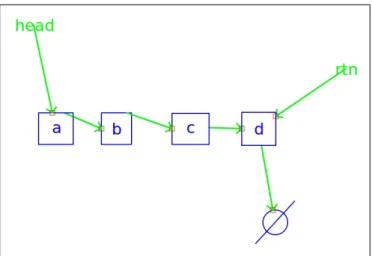
(a) CoMo: “How do you handle this case?” (b) User: “Like this.” Figure 1-2: The next question CoMo asks is about a list with four nodes.
Now that the interaction has been initiated and the user has explained what kind of structure they are talking about, CoMo begins to go through the list of cases (above) that the code synthesis system [28] requires to successfully synthesize code2. CoMo asks its first question about the manipulation by saying, “How do you handle
this case?” and generating the list with four nodes seen in Fig. 1-2a. The user clicks and drags on the pointers’ heads to reverse the list. Once the user is done reversing the list, they say, “Like this.”
(a) CoMo: “How do you handle this case?” User: “Do nothing.”
(b) CoMo: “How do you handle this case?” User: “Do nothing.”
Figure 1-3: The next two questions CoMo asks are about the list with one node and the empty list.
Next, CoMo asks about the empty list and the list with one node. Fig. 1-3 shows the structures that CoMo generates. In response to each question, the user says, “Do nothing” because these lists look the same reversed. CoMo has finished asking all its questions, and so it says, “I think I understand.” The purpose of the interaction was to explain to CoMo what a linked list reversal manipulation looks like, so that it could synthesize code. To initiate the code synthesis process, the user says, “Generate code.” CoMo responds with, “I will try” and code synthesis commences.
To synthesize code, CoMo generates a description of the interaction that can be used by the Storyboard Programming Tool [28] to synthesize C code. Once code has been synthesized, it is displayed next to all of the examples in the interaction (see Fig. 1-4). The user verifies that the code is correct by having CoMo symbolically execute the code on an example. The user switches to the initial list with four nodes3 and says, “Animate the code.” CoMo resets the list to its initial state and animates the code’s execution. As part of the animation, CoMo generates the two temporary
3As described in Chapter 4, the user can switch between existing examples by clicking on tabs
Figure 1-4: CoMo animates the code’s execution on a structure. The line “tmp1.ptr0=tmp2” (highlighted in green) has almost completed its animation; the pointer attached to b has almost completed its movement from the c node to the a node.
pointers that are not present in the original diagram (tmp1 and tmp2; see Fig. 1-2) and highlights the line of code it is executing in green while animating it. Fig. 1-4 shows the middle of the process, as CoMo executes the line “tmp1.ptr0=tmp2.”
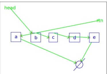
As demonstrated above, CoMo is able to generate example structures. CoMo uses the general description given at the beginning of the interaction by starting with the skeleton (Fig. 1-1a) and repeatedly replacing the ellipsis with one of the provided inductive steps (Fig. 1-1b)4. The user would like to test out the code on an example that CoMo has not seen yet, so they say, “Generate a structure with five nodes.” CoMo creates the structure and displays it on a new canvas next to the code. “Animate the code,” the user says again. Fig. 1-5 shows CoMo animating the
4Due to the nature of the list description, CoMo will only be able to generate lists with at
least three nodes. Empty structure generation and single-node structure generation are handled by copying existing elements from other examples and assigning all pointers to null.
Figure 1-5: CoMo animates the code’s execution on a new structure. The line “head=head.ptr0” is in the middle of being animated; the head pointer is half way through its transition between that c and d nodes.
reversal as it executes the line, “head=head.ptr0.” The user verifies that the code works on this example, and is satisfied that the code is functionally correct.
1.3
Code Synthesis
CoMo synthesizes code using a system called the Storyboard Programming Tool (SPT) [28]. A code synthesis system (e.g., [30, 27, 14]) attempts to synthesize code based on a textual description of a manipulation. SPT’s description consists of a set of example data structures as they are configured before and after the manipulation, along with an outline of the expected code. The code outline contains simple log-ical constructs (e.g., while and if statements) and placeholders where synthesized code must be inserted. Systems like these model code synthesis as a search through a symbolic representation of a constrained space of programs. These systems must
have two key properties: the ability to constrain the symbolic space of programs, and the ability to search in it. These systems use the code outline to define this sym-bolic search space, and the pointer assignments in the examples’ input and output states to constrain it. More succinctly put, code synthesis is the process of solving the constraint problem defined by the code outline and the set of examples consist-ing of structures’ input and output states. Engagconsist-ing CoMo in its mixed-initiative symmetric-multimodal interaction improves upon using a text-based code synthesis system (like SPT) alone by:
1. Removing rudimentary dead code.
2. Engaging in a mixed-initiative, symmetric-multimodal interaction and convert-ing data structure manipulation diagrams into the input and output states that the code synthesis system requires.
3. Providing feedback about what kinds of scenarios to provide, namely that the following examples suffice for SPT [28] to synthesize correct code for many simple data structure manipulations:
(a) Examples containing structures with four, one, and zero nodes.
(b) Examples enumerating all size comparisons between the main structure when it has 4, 1, and 0 nodes and any auxiliary structures with one or no nodes.
(c) Examples comparing single-node structures with different values in multi-ple structure scenarios where the structure is ordered.
4. Removing the need to provide a code outline (called a control flow graph) to the code synthesis system by automatically selecting one.
5. Aiding the user in verifying synthesized code’s correctness by animating it, thereby facilitating the user’s own checking of the code.
1.4
Interaction
CoMo’s goal is to satisfy the code synthesis system’s requirements in as natural an interaction as possible. Previous work provides several insights into what kinds of interactions are natural and effective, namely:
1. Direct-manipulation interfaces—those where the user can directly manipulate a representation of the system’s underlying model—facilitate users working with the system by exposing them to a representation of the system’s model. This makes it easier for the user to understand why the system behaves the way it does.
2. Symmetric-multimodal interfaces (e.g., [1])—those that employ multiple modes of interaction for both input and output—are more flexible and feel more natural than interfaces that use only a single mode of input. The modes can make up for each others’ weaknesses.
3. Mixed-initiative systems (e.g., [22])—those that allow both the user and the system to initiate interactions—are more effective than those that require the user to follow a prescribed script.
The remainder of this section describes these points in more detail.
Direct-manipulation interfaces are interfaces that present a system’s underlying model in a concrete form that can be manipulated in a direct way, usually by pointing and clicking. For example, CoMo allows users to demonstrate manipulations by updating a data structure in-place; users click and drag pointers to reassign them. CoMo demonstrates how direct-manipulation interfaces can make abstract actions (in this case reassigning pointers) more easily understandable by replacing them with physical ones (in this case grabbing and moving arrows).
Symmetric-multimodal interfaces are interfaces where all modes of input are also modes of output. Different tasks are more quickly and succinctly expressed by differ-ent modes of communication. For example, work by Adler [1] demonstrated that tasks like specifying an object’s direction of motion are more easily expressed by drawing
a line, while answering a yes or no question is more easily expressed with speech—by simply saying “Yes” or “No.” Multimodal interfaces are able to take advantage of the strengths of the modes they employ, while interfaces using only one mode of input must deal with that mode’s weakness.
Mixed-initiative interfaces are interfaces that allow both the user and the system to initiate or guide an interaction. These sorts of interfaces remain dynamic and responsive by guiding the user through a task (e.g., by keeping a list of steps to perform) while allowing them to change the interaction’s focus (e.g., jumping ahead a step) at any time. CoMo’s interface is mixed-initiative because either the user or CoMo can initiate an interaction, e.g., by asking a question or giving a command.
Interactions differ by domain. For example, circuit diagrams are drawn with different symbols than chemistry diagrams. To draw data structure manipulation diagrams, I needed to determine how people draw operations on data structures. To find out, I conducted a user study that paired 10 experts with 10 novices, and asked the experts to explain a linked list reversal and a binary tree left rotation to the novices. Chapter 3 discusses the user study and describes the interesting interactions observed, namely that:
1. Teachers tend to ask students what they know before starting to explain some-thing.
2. Teachers tend to describe manipulations in terms of before and after states, but sometimes explain the process of the manipulation in detail.
3. Visual vocabularies are easily learned, understood, and used by people.
4. Teachers sometimes used an unannounced, unexplained drawn shorthand that was immediately understood by students.
5. Interactions were mixed-initiative in the sense that teachers generally initiated interactions by explaining a manipulation, but students also initiated interac-tions by asking quesinterac-tions.
1.5
Contributions
The contributions presented fall in three categories. The first contribution includes the findings from a user study, presented in Chapter 3. The second contribution is CoMo, the first conversation-to-code smart whiteboard system, capable of holding a mixed-initiative symmetric-multimodal interaction about 50 manipulations on 8 structures and correctly synthesizing functioning C code. The third contribution is the novel mixed-initiative code-generation framework (MICGF) that CoMo implements to engage in interactions about data structure manipulations, described in Chapter 5.
Chapter 2
Related Work
CoMo is motivated by two fields of research: programming by example (PBE; some-times called programming by demonstration, or PBD, since the examples are demon-strated) and multimodal systems—systems that employ multiple modes of input (and sometimes output, also). As Lieberman [21] explains, work in programming by exam-ple has two dominant approaches: creating systems that have a strong background in AI and theory, and systems that rely heavily on heuristic approaches. Generally these systems’ implementations start by performing exploratory user studies to determine how best to structure the user interaction and often end with evaluative user studies that determine how effective the system was at interacting with the user. This chap-ter discusses some exploratory user studies, the systems that were created with the insights from those studies, and finally it discusses some interesting evaluative user studies that reveal more about sketch-based interfaces.
Adler and Davis [2] and Bischel et al. [6] performed two separate studies showing that multimodal human interactions are complex, and interaction practices may vary slightly from domain to domain. Adler and Davis sought to determine what natural interactions about circuit diagram drawings look like. They explored the uses of color and gesture with a multimodal system by asking a subject to explain a mechanical system to a researcher. The study’s setup allowed the researcher to guide the inter-action but removed the ability to observe how a natural human-human interinter-action of this kind would proceed without the influence of the researcher. Since I wanted
to observe natural interactions between an expert and a novice, my study removed a researcher from the dialog. Bischel et al.’s continued work sought to create a sketch recognition system capable of accurately distinguishing gestures from non-gestures. Their user study focused on mechanical diagram drawings also, however like my study, the researcher was not involved in the discussion.
Plimmer and Apperley [26] provide more motivation for CoMo. They conducted a user study that found the flexibility inherent in sketch-based interfaces leads users to do more revisions of a graphical user interface design, which results in better final designs. Cossairt et al. [11] showed a similar result in the domain of mathematics problems. Their system recognized written set equations and generated a Venn dia-gram representation. In a user study they performed, they found that students using the system were better able to complete a math quiz on set equations than those using pen and paper alone. This result is likely due to the fact that there is a dif-ference between how easily understood a visual representation (like a Venn diagram) is and how much harder it is to parse a written representation (like a set equation). By parsing the set equations for students, they were able to focus on parsing and understanding the visualization and did not have to parse the set equations. This is a very similar task to CoMo’s—parsing, abstracting, and visualizing a user’s sketch in a way that makes it easier to understand—the two major differences being the different domain and the direction of the task CoMo performs. Instead of converting a textual representation (set equation) of a problem to a diagrammatic one (Venn diagram), it converts the diagrammatic representation (data structure manipulation diagram) to a textual one (code).
Another motivating user study is presented by Good et al. [12]. Their study found that humans are not adept at remembering specifics like corner cases when specifying the exact rules to describe an observed behavior in a video game. In fact, errors of omission were the most frequently performed kind of error the subjects performed (74% of all errors). This observation greatly motivated CoMo’s questions; it is another reason that CoMo asks questions about corner case examples.
CoMo’s greatest motivation. He called the system Midos [1] and coined the phrase “symmetric-multimodal user interface” to describe it. Midos is a system that allows users to qualitatively describe a physical system (like a Rube Goldberg machine) by specifying things like which block hit which block, and how the resulting collision affects them. It determines which question to ask by qualitatively simulating the physics of the scenario, determining what it does not know about that simulation, and asking a clarifying question. There are two major differences between Midos and CoMo: the domain and the exact method used to generate questions. The second difference results directly from the first: while Midos asks about holes in its understanding of a simulation, CoMo has no simulation to query, and so uses a predetermined list of examples shown to work with its code synthesis system.
Traynor et al. [34] report on a study about their system with very similar goals as CoMo: enabling non-experts with a system that facilitates interaction. Their system attempts to enable non-technical end users to to exercise the capabilities of a geographic information system by using Modungo et al.’s [24] programming by demonstration language. Their study found that, despite its shortcomings, their vi-sual PBD interface is preferred over alternatives such as using SQL. Similarly, Kahn’s ToonTalk [19] is a system that attempts to make expert tasks more accessible to non-experts—in this case focusing on programming. Like CoMo, this system abstracts programming concepts with real-world objects. However, instead of boxes and arrows, it uses the analogy of a town with working robots in it.
Bauer et al.’s Trainable Information Assistants (TrIAs) [5] cooperate with users to solve a problem. Like CoMo, TrIAs are agents that are specialized to help a user with a single task in a mixed-initiative interaction. Users can do things like give examples and hints to the system while the system can do things like ask for more examples and present its current hypothesis to the user. Unlike CoMo, these agents do not interact with the user multimodally with speech and sketch; instead, interaction is limited to a traditional WIMP interface [16].
Buchanan et al.’s CSTutor [8] is very similar to CoMo; differences arise from its different goal: CSTutor teaches students simple data structure manipulations. In
contrast, CoMo is capable of discussing a data structure manipulation and gleaning enough information to initiate code synthesis with. This difference can be anthropo-morphized by saying, CoMo is a student that attempts to learn a new data structure manipulation whereas CSTutor is (as the name suggests) a tutor, attempting to teach a data structure manipulation. As a result, CoMo was programmed with knowledge of what pointers and nodes are instead of, like CSTutor, with the details of its structures and manipulations.
Alvarado et al. [4] created a system called LogiSketch, that simulates drawn digital circuit diagrams. LogiSketch is similar to CoMo in that it automates a task for users, however it differs both in the method of interaction (LogiSketch does not interact multimodally) and in the domain. CoMo’s interaction was, in part, motivated by two findings from the pilot study they performed: that large sketches tend to get messy and hard to understand after some time, and that subjects were engaged in the interaction. Like LogiSketch, CoMo cleans users’ diagrams to help de-clutter the canvas but also generates sketches itself whenever possible, thereby further avoiding user-introduced visual clutter.
Chen et al. [9] created a system called Sumlow that recognizes Unified Modeling Language (UML) diagrams and allows them to be exported to a third party CASE tool. They evaluated their system based on Green and Petre’s “Cognitive Dimen-sions” [13] and found that, when compared with traditional CASE tools, Sumlow benefited from the flexibility that a sketch-based interface allowed, but suffered from sketch recognition errors.
Kaiser [20] showed with a user study of their system that multimodal speech and sketch help to disambiguate one another, creating user interfaces that aid users in avoiding errors by using the strengths of each mode of input. Further, the system attempts to learn to better itself, which is roughly related to what CoMo attempts to do.
Mangano et al. made a system, called Calico [23], with a goal similar to CoMo’s: aiding users in design. They evaluated Calico by running a pilot study involving 16 pairs of participants designing a traffic light simulator with the system and found
that Calico helped users even if they did not use all of its features. Mangano et al. determined that more training may be necessary for people to take full advantage of their system’s features.
One final system that warrants mention is Roy’s Synbad [27]. Like SPT [28], Synbad uses a SAT solver to synthesize code from constraints derived from a set of concrete examples of manipulations, but boasts an improved synthesis time over SPT. Future versions of CoMo may wish to take advantage of Synbad’s improved runtime.
Chapter 3
Observational User Study
In this chapter, I describe a user study that I conducted to observe how data structure manipulations are explained at a whiteboard. I asked pairs of subjects to discuss two data structure manipulations and ensured that the pairs consisted of one subject who was familiar with the manipulations (e.g., a computer science undergraduate) and one who was completely unfamiliar with them, even how they were drawn. The user study presented here served as a guide to CoMo’s interaction. In this user study I concluded that CoMo should:
1. Remember the names of the data structures and manipulations it has encoun-tered and recall them when asked.
2. Use direction to determine what kind of pointer an arrow represents.
3. Allow the user to describe manipulations either as input and output states or with detailed pointer manipulations.
4. Allow the user to edit structures in place.
3.1
Participants
I recruited 20 undergraduate volunteers and asked each one:
2. whether they had heard of a linked list
3. whether they had heard of a binary tree
4. when they were available to participate
Based on their response, each was classified as either a “teacher” or a “student.” Teachers and students were paired based on their availability, and asked to spend an hour in a conference room teaching and being taught the manipulations. Subjects were not notified of whom they were paired with before the session began.
Teachers Students
Male 9 2
Female 1 8
Right-handed 9 9
Left-handed 1 1
Electrical Eng. and Comp. Sci. (EECS) 7
-EECS & Math 3
-Undeclared - 4
Mechanical Engineering - 3
Brain and Cognitive Sciences (BCS) - 1
Chemistry & Linguistics and Philosophy - 1
Music and Theater Arts & BCS - 1
Table 3.1: Participants’ Demographic Information
Table 3.1 describes the participants’ demographic information1. Teachers had taken an average of three relevant computer science courses that included topics such as “Introduction to CS,” “Software Engineering,” and “Algorithms.” Two out of the ten students had taken a “CS for non-CS Majors” course. One student had taken “Advanced Placement CS” in high school. Two students had some past experience programming. No students had been taught anything about either of the data struc-ture manipulations before the session.
3.2
Procedure
Each session consisted of a teacher describing two data structure manipulation de-scriptions to a student, one manipulation at a time. I chose two simple data structure manipulations: a singly-linked list reversal and a binary tree left rotation. The teacher was asked to teach the linked list reversal first because it was simpler and students were complete novices. I assumed that easing them into the abstract concept of data structure manipulations would make it more likely that students could learn the ma-nipulations effectively, thereby engaging in interesting interactions to study. Unlike [2], I decided against participating in the conversations, as I wanted to observe how data structure manipulations were both learned and taught as well as what form the learning interactions would take without my influence.
a head b c a head a head b c d e f
(a) Reverse these lists.
root 2 8 4 1 6 5 3 7 9 10 1 2
(b) Balance this tree. Figure 3-1: Exercises teachers were asked to give students.
To test the students’ understandings, teachers were asked to give their students a set of prepared exercises (Fig. 3-1) at the end of each description.
Sessions were held at a whiteboard in a private conference room and videotaped. The camera was visible to the subjects throughout the session. Before the session began, subjects were briefed privately in the same room. Each briefing consisted of asking the subject to read and sign a consent form. Next, the subject was asked to review printed instructions and ask any questions they might have. The teacher was
briefed before the student. The subject not being briefed was asked to step out of the room during their partner’s briefing. When both subjects had been briefed and all their questions had been answered, the camera was started and they were asked to begin the linked list reversal description.
During the descriptions, I remained in the room working at a computer with my eyes averted from the subjects. My purpose was to start and stop the camera and ensure it was working during the descriptions. I did not interact with the subjects or answer questions during either description, however, subjects were given an opportu-nity to ask questions between descriptions. I took them out of the room to answer any questions they might have individually.
After both descriptions were done, the subjects were given a two-page question-naire that presented ten statements the subject was asked to evaluate on a five point Likert scale, asked them to provide demographic information including their previous programming experience, and gave them an opportunity to give any additional com-ments on the session. Subjects were informed that their partner would not see their responses, and that I would not look at them until they left the room. The teachers’ and students’ questionnaires differed slightly in their Likert statements (discussed below). When they completed their questionnaires, subjects were thanked and com-pensated with two movie ticket vouchers.
3.2.1
Instruction Sheets
Teachers and students were given different instruction sheets. The teachers’ instruc-tion sheets consisted of two double-sided pages, the first page outlined the linked list reversal, the second outlined the binary tree left rotation. The fronts of these pages contained brief descriptions of the manipulations they were to teach, and the backs contained exercises to give to the student after they understood the manipulation (Fig. 3-1). I ensured that the teachers were already familiar with the manipulations presented; the data structure manipulation instructions were there only to ensure the teachers had an aide to get back on track, should the need arise. A cover sheet was included with the teachers’ instructions. This stressed four key points (discussed
below) to ensure a rich interaction took place. The students’ instructions were much simpler. They consisted of one single-sided page explaining, at a high level, what data structures and data structure manipulations are. I ensured that students had little or no experience with data structures, so their instruction sheets presented them with some example data structure diagrams as well (Fig. 3-3).
Teachers’ reminders:
1. Explain the process—don’t just write pseudo code.
2. Don’t worry about being perfect, do your best. You are acting as a teacher—this is not a job interview.
3. Do your best to make sure your student understands the manipula-tion before showing them the examples.
4. Use this prompt only as a guide. Do not show your student this prompt as a teaching aide.
Students’ reminders:
5. Ask questions if something is confusing. 6. It’s okay to draw on the board, yourself.
Figure 3-2: Reminders presented to subjects in order to encourage a rich interaction. These were placed on the front sheet of subjects’ instructions.
Teachers’ cover sheets and students’ instruction sheets made an effort to stress things that would encourage a rich interaction. Fig. 3-2 quotes the reminders in the instructions I gave. I wanted to avoid situations where the teacher simply wrote pseudo code to explain the manipulation (item 1), was overly nervous about getting the details right (item 2), or showed the student the images on the prompt instead of drawing on the whiteboard themselves (item 4). I also wanted to ensure the student understood the manipulation before being given the exercises (item 3), and was willing to ask questions (item 5) and use the whiteboard themselves, without making the student feel as though they must (item 6).
3.3
Hypotheses
Before beginning the study, I posited several hypotheses. These hypotheses came from my previous experience in teaching computer science, and from my previous work in designing and creating sketch interfaces. The first hypothesis—implicit in the teachers’ instruction sheets—was that having someone successfully complete exercises can determine whether a person understands a manipulation.
loop a b c d pascal 1 1 1 1 1 2 1 3 3 1 top John Xiao Dieter (a) Data structure vocabularies presented to students.
a head b c d root 2 3 5 1 4 a z head root 2 7 4 1 6 5 3 (b) Data structure vocabularies presented to teachers.
Figure 3-3: Sample visual data structure vocabularies presented to subjects.
I hypothesized that for the purposes of creating a system capable of holding a limited multimodal conversation, fixing the system’s sketch vocabulary—the set of symbols the system recognized—would simplify implementation without sacrificing usability. I further hypothesized that the sketch vocabulary consisting of nodes drawn as boxes or circles and pointers drawn as arrows would be one such vocabulary. Fig. 3-3 shows a sampling of the example structures I presented to subjects in their instruction sheets. I settled on this vocabulary, because I use it myself, and I have noticed teachers and colleagues use it.
teacher is the only one expected to draw on the whiteboard unless a student is ex-plicitly instructed to do so. I hypothesized that—despite being exex-plicitly labeled as “student” and “teacher”—the student would naturally interact with the whiteboard during the sessions, because people learn better when interacting with the same sur-face.
My final hypothesis was that, not only do people prefer interacting with the same surface, but they prefer interacting with the same structure. That is, I hypothesized that when teachers drew the required exercises to test their students’ understanding, the student would prefer to draw over the same structure as opposed to drawing a new structure that reflected the changes.
3.4
Limitations
Students’ prompts may have overly biased them to draw at the board by including item 6, weakening my ability to draw a positive conclusion on the “same surface” hypothesis.
Studying pairs consisting of one expert and one novice prevented me from deter-mining how people might cooperate to settle on a visual vocabulary. With this study’s setup, I cannot determine whether more experienced students may have attempted to alter the visual vocabulary their teachers presented.
Asking teachers to give students exercises may have biased them toward confirm-ing the hypothesis that successfully completconfirm-ing exercises accurately tests students’ knowledge. On the other hand, it gave me the opportunity to see whether they strongly disagreed with it, as they were free to choose not to give any exercises.
I asked participants to discuss only simple data structure manipulations. Had I asked the subjects to discuss more complex manipulations, I may have gotten more interesting observations involving aspects of more complex manipulations. For exam-ple, the structure of this study did not allow me to determine how people describe the balancing algorithm involved in an AVL tree. I decided against using more complex manipulations for practical reasons; finding a student demographic that was
knowl-edgeable enough to understand these more complex manipulations but that had not yet seen them would be prohibitively difficult.
3.5
Results
The videos and questionnaires were reviewed and aggregated. This section reports the aggregate results.
3.5.1
Analysis
0 10 20 30 40 1 2 3 4 5 6 7 8 9 10 Duration (min ) Session Number(a) The durations of each description by session, with averages.
0 10 20 30 40 50 60 70 1 2 3 4 5 6 7 8 9 10 Duration (min ) Session Number
(b) Combined total of both descriptions by session, and average. Figure 3-4: The time it took each session’s descriptions and their sum.
Fig. 3-4 shows each description’s duration. The blue bars (left) in Fig. 3-4a show the first session (linked list reversal) and the green bars (right) show the second session (binary tree rotation). The blue line (lower) denotes the average linked list time of 12:58 and the green line (upper) denotes the average binary tree time of 23:51. Tree descriptions took 84.4% longer on average. Plots in Fig. 3-4b are the sum of the plots in Fig. 3-4a. The shortest session (8) took 19:39 and the longest (9) took a total of 63:26. Average session length was 36:47 (denoted by the horizontal line in Fig. 3-4b).
All durations were measured between the time the teacher began talking about the data structure manipulation and the time the student completed the final exercise.
Unsurprisingly, list reversals took much less time than tree rotations on average. However, in sessions 1 and 9 the list reversals took more time than the tree rotations. After reviewing the recordings of these sessions, I determined that there were two different reasons for this. In session 1, the teacher was quite nervous and ended up stumbling over themselves. By the second description, they had relaxed enough that the description went more smoothly and thus more quickly. In session 9, the partici-pants happened to know each other2. The teacher knew that the student wanted to be a computer science major, so in addition to describing the manipulation in great detail, they also described the inner workings of a computer to clarify why algorithms must proceed as they do. For example, the teacher explained why temporary pointers are needed: they ensure memory references are not lost. This extensive background knowledge did not need to be repeated, so the second description (though more com-plex) took less time.
Though students were explicitly told they could draw on the board, their instruc-tions did not require them to do so. As a result, the students in sessions 3 and 9 sat at a table and took notes on their instruction sheets. They did not get up to interact with the teacher at the board before the exercises were given. To reference something on the board while asking a question, these students pointed at the item they were referencing without getting up from their seats. Student 9 came up only to perform the exercises the teacher gave them. Interestingly, student 3 attempted to do the exercises on their instruction sheet. For the simple linked list manipulation, this was not a problem. For the tree manipulation, however, the student had trouble working through the exercise on their own, and approached the board to work with the teacher’s initial drawing. This suggests that working with the same drawing may make it easier to think through manipulations than attempting to memorize the ma-nipulation and work on a separate surface. However, since this is this study’s only observation of this kind, I cannot draw a concrete conclusion.
I enjoyed explaining the binary search tree rotation. Most of the time during the LLR was spent on questions. The session went by quickly
I enjoyed explaining the linked list reversal. We spent a lot of time clarifying things. I spent more time talking than the student.
Two people is probably too many for one white board. Most of the time during the BTR was spent on questions. Some questions were confusing.
The student interrupted often to ask questions.
Strongly
Disagree Neutral StronglyAgree
(a) Statements presented to teachers.
I found the binary search tree description interesting. Most of the time during the LLR was spent on questions. The session went by quickly.
I found the linked list description interesting. We spent a lot of time clarifying things. I spent more time talking than the teacher.
Two people is probably too many for one white board. Most of the time during the BTR was spent on questions. Understanding the binary search tree rotation was easy. Understanding the linked list reversal was easy.
Strongly
Disagree Neutral StronglyAgree
(b) Statements presented to students.
Figure 3-5: Subjects’ responses to qualitative questions on a 5-point Likert scale. Average responses are displayed between minimum and maximum values. Note that the manipulation names were abbreviated to fit in the figure; subjects were presented with unabbreviated text.
Fig. 3-5 shows the aggregate results of subjects’ level of agreement or disagreement with the statements. These questions were meant to determine whether the general structure of the interaction was correct, i.e., whether interactions of this kind were enjoyable for the subjects. I found that teachers did not think an unusual amount of questions were asked and that they felt they understood the questions that were asked. Unsurprisingly, students found the tree manipulation to be more difficult to understand than the list manipulation and were slightly more critical of themselves than the teachers were of them. Teachers and students agreed that teachers spent more time talking than students and that subjects were comfortable writing at the board together. In all, I determined that the interaction was enjoyable and productive for both subjects.
In seven of the ten sessions (eight of the twenty descriptions) the teacher began by asking the student whether they had heard of the data structure, for example by asking, “Have you heard of a linked list before?” or “Do you know what a linked list is?” In each case, the student replied that they had not, so the teacher started by explaining what the data structure was, why one might use it, and (in some cases) how it differed from similar structures.
Session 3 was one such session. The teacher asked the student, “Do you know what’s a tree in computer science?” Due to the teacher’s accent, the student mis-understood the teacher to be asking if the student knew how to represent a three in binary. After repeated verbal attempts to clarify what they meant, the teacher finally drew a biological tree and a binary tree. They pointed to the drawing of the binary tree and asked the student if they had seen one before. This was an unexpected observation. When verbal communication failed, the teacher resorted to the next available mode of interaction: sketch. This successfully communicated the question and the interaction was able to continue.
In eleven of the twenty descriptions, teachers used the visual vocabulary presented in the instruction sheet. In eight of twenty descriptions, the visual vocabulary used was very similar, but not identical. In only one instance (the list description in session 1) was the vocabulary used significantly different from the one presented in
(a) An example of the vocabulary used in session 1 for the linked list reversal. Note that it is significantly different from the vocabulary presented in the instruction sheet.
(b) An example of the vocabulary used in session 1 for the binary tree left rotation. Note that it is nearly identical to the vocabulary presented in the instruction sheet.
Figure 3-6: Examples of the vocabularies used in the first session.
the teacher’s instructions. Fig. 3-6 shows an example of the vocabulary used in session 1. This suggests that the vocabularies I chose were reasonable, supporting my hypotheses. Further, in all descriptions, students copied their teachers’ visual vocabularies with no apparent difficulty3. This, again, supports my hypothesis that setting a visual vocabulary does not interfere with a person’s ability to understand a data structure; even complete novices are able to quickly learn and understand the meaning of structures drawn with this visual vocabulary. Once teachers chose a vocabulary, they did not change it. However, in four of the twenty descriptions
teachers spontaneously introduced a shorthand sketch vocabulary. Presumably to speed up drawing, teachers omitted the outline of nodes (drawing only its contents, e.g., “a” or “7”) and the heads on arrows (drawing them as simple lines). The only characteristics defining the data’s structure were nodes’ and lines’ relative positions. For example, binary trees were drawn with left and right children at their bottom left and bottom right, connected by a line. Fig. 3-7 shows an example of the type of shorthand observed (top-right) next to an example of the visual vocabulary used throughout most of the conversation (left). The placement of the nodes and pointers was unambiguous and consistent enough for the student to understand the new visual vocabulary immediately, without the need for an explanation.
Figure 3-7: An immediately understood visual shorthand.
In six of the tree descriptions (but none of the list descriptions), teachers gave their students additional exercises before giving them the exercises in their instructions. This may indicate that one way people choose to verify someone else’s understanding is to quiz them. However, this observation may have been due to the bias present in the instruction sheets; asking the teachers to give examples likely influenced them. Due to this bias, I cannot conclude that successfully demonstrating examples neces-sarily means a person understood a manipulation fully.
In all but session 9, teachers demonstrated the manipulations by drawing the state of a structure with a concrete number of nodes as it appears before and after the